1. Survey Summary file4. Introductory Note Purpose of Survey The survey of the designated...
12
An Coimisiún um Rialáil Cumarsáide 1 Dockland Central, Guild St, Dublin 1 1 Lárcheantar na nDugaí, Sráid na nGildeanna, BÁC 1 Tel | Teil +353 1 804 9600 www.comreg.ie Programme of Measurement of Non-Ionising Radiation Emissions Site Survey Report 1. Survey Summary Address of Transmitter Site Surveyed: Mountjoy Garda Station, 399 North Circular Rd, Phibsborough, Dublin 7 Site Type: GSM, UMTS, LTE, Tetra Survey Date: 22/03/2019 Measurement Location: (at point of maximum non-ionising radiation near site) On public footpath, directly outside entrance to Mater hospital mortuary, opposite transmitter location. Measurement Location Coordinates: LAT deg min sec LONG deg min sec N 53 21 37.3 W 6 16 4.6 Purpose and Conduct of Survey: Non-ionising electromagnetic radiation levels were measured at the point of highest emissions which was determined near the site, in order to assess compliance with the international ICNIRP Limits for general public exposure to non-ionising radiation. Compliance with the ICNIRP limits is a condition of a General Authorisation for an electronic communications network/service as well as of various Wireless Telegraphy licences issued by the Commission for Communications Regulation (ComReg). Overall Conclusions of the Survey Frequency Selective Measurements: (Individual emissions measured at specific frequencies) Below ICNIRP Public Limits (Compliant) Total Exposure Quotient: (Assessment of cumulative emissions from multiple transmitters) Below ICNIRP Public Limits (Compliant) 2. Surveyors Survey conducted for ComReg by: Compliance Engineering Ireland Ltd. Survey Engineer(s): Report Writer: Report Reviewer: Michael Reilly, BEng Michael Reilly, BEng John McAuley, MEng
Transcript of 1. Survey Summary file4. Introductory Note Purpose of Survey The survey of the designated...
An Coimisiún um Rialáil Cumarsáide
1 Dockland Central, Guild St, Dublin 1
1 Lárcheantar na nDugaí, Sráid na
nGildeanna, BÁC 1
Tel | Teil +353 1 804 9600 www.comreg.ie
Programme of Measurement of Non-Ionising Radiation
Emissions
Site Survey Report
1. Survey Summary
Address of Transmitter Site Surveyed:
Mountjoy Garda Station, 399 North Circular Rd, Phibsborough, Dublin 7
Site Type: GSM, UMTS, LTE, Tetra
Survey Date: 22/03/2019
Measurement Location: (at point of maximum non-ionising radiation near site)
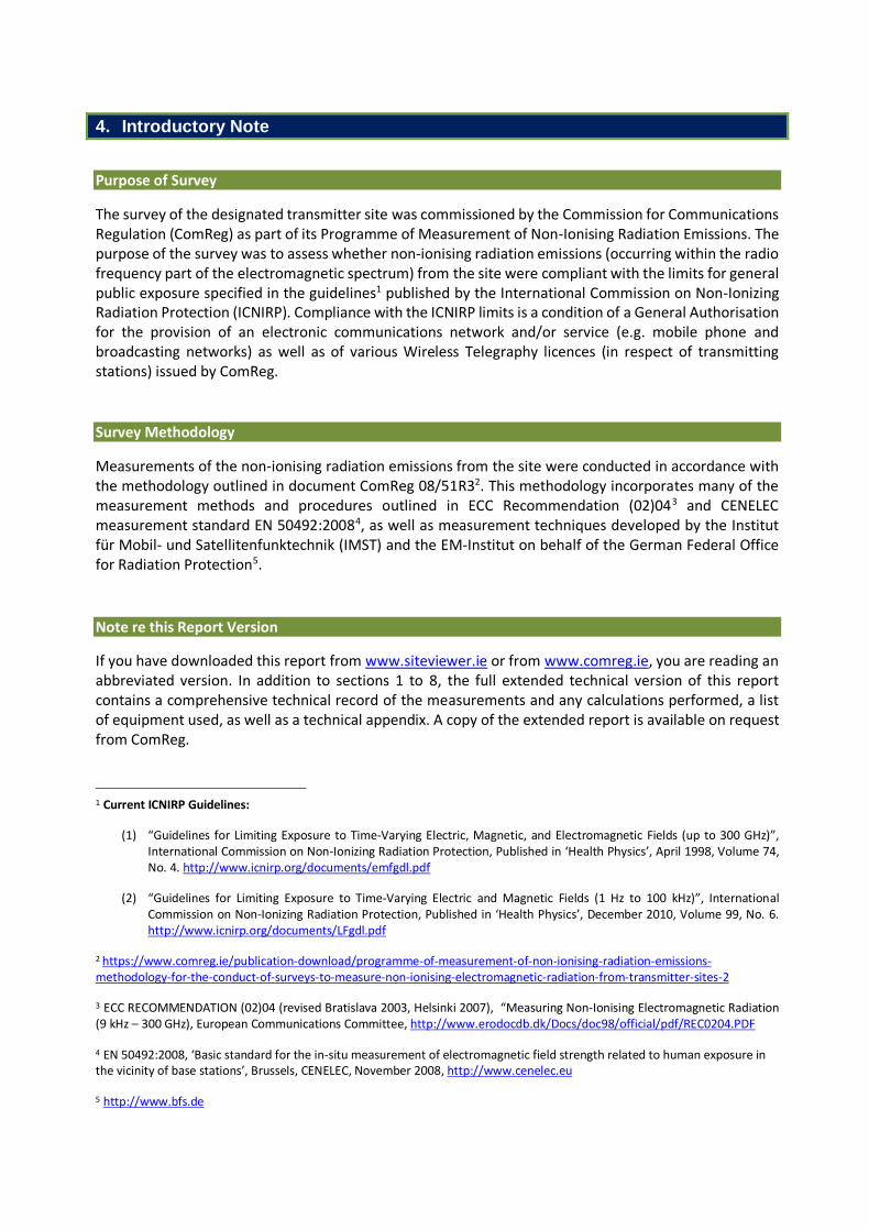
On public footpath, directly outside entrance to Mater hospital mortuary, opposite transmitter location.
Measurement Location Coordinates:
LAT deg min sec LONG deg min sec
N 53 21 37.3 W 6 16 4.6
Purpose and Conduct of Survey:
Non-ionising electromagnetic radiation levels were measured at the point of highest emissions which was determined near the site, in order to assess compliance with the international ICNIRP Limits for general public exposure to non-ionising radiation.
Compliance with the ICNIRP limits is a condition of a General Authorisation for an electronic communications network/service as well as of various Wireless Telegraphy licences issued by the Commission for Communications Regulation (ComReg).
Overall Conclusions of the Survey
Frequency Selective Measurements: (Individual emissions measured at specific frequencies)
Below ICNIRP Public Limits (Compliant)
Total Exposure Quotient: (Assessment of cumulative emissions from multiple transmitters)
Below ICNIRP Public Limits (Compliant)
2. Surveyors
Survey conducted for ComReg by:
Compliance Engineering Ireland Ltd.
Survey Engineer(s): Report Writer: Report Reviewer:
Michael Reilly, BEng Michael Reilly, BEng John McAuley, MEng
3. Survey Location Details
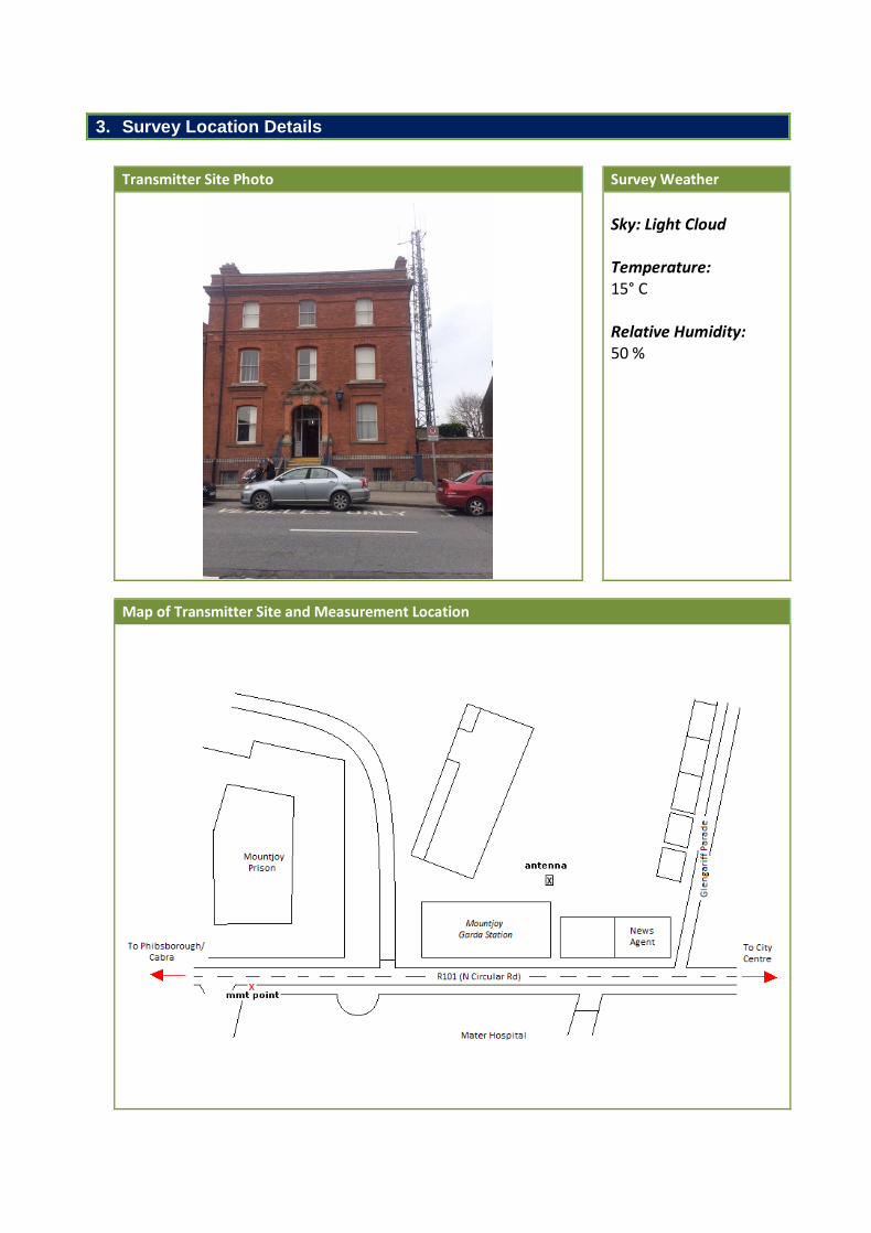
Transmitter Site Photo Survey Weather
Sky: Light Cloud Temperature: 15° C Relative Humidity: 50 %
Map of Transmitter Site and Measurement Location
4. Introductory Note
Purpose of Survey
The survey of the designated transmitter site was commissioned by the Commission for Communications Regulation (ComReg) as part of its Programme of Measurement of Non-Ionising Radiation Emissions. The purpose of the survey was to assess whether non-ionising radiation emissions (occurring within the radio frequency part of the electromagnetic spectrum) from the site were compliant with the limits for general public exposure specified in the guidelines1 published by the International Commission on Non-Ionizing Radiation Protection (ICNIRP). Compliance with the ICNIRP limits is a condition of a General Authorisation for the provision of an electronic communications network and/or service (e.g. mobile phone and broadcasting networks) as well as of various Wireless Telegraphy licences (in respect of transmitting stations) issued by ComReg.
Survey Methodology
Measurements of the non-ionising radiation emissions from the site were conducted in accordance with the methodology outlined in document ComReg 08/51R32. This methodology incorporates many of the measurement methods and procedures outlined in ECC Recommendation (02)043 and CENELEC measurement standard EN 50492:20084, as well as measurement techniques developed by the Institut für Mobil- und Satellitenfunktechnik (IMST) and the EM-Institut on behalf of the German Federal Office for Radiation Protection5.
Note re this Report Version
If you have downloaded this report from www.siteviewer.ie or from www.comreg.ie, you are reading an abbreviated version. In addition to sections 1 to 8, the full extended technical version of this report contains a comprehensive technical record of the measurements and any calculations performed, a list of equipment used, as well as a technical appendix. A copy of the extended report is available on request from ComReg.
1 Current ICNIRP Guidelines:
(1) “Guidelines for Limiting Exposure to Time-Varying Electric, Magnetic, and Electromagnetic Fields (up to 300 GHz)”, International Commission on Non-Ionizing Radiation Protection, Published in ‘Health Physics’, April 1998, Volume 74, No. 4. http://www.icnirp.org/documents/emfgdl.pdf
(2) “Guidelines for Limiting Exposure to Time-Varying Electric and Magnetic Fields (1 Hz to 100 kHz)”, International Commission on Non-Ionizing Radiation Protection, Published in ‘Health Physics’, December 2010, Volume 99, No. 6. http://www.icnirp.org/documents/LFgdl.pdf
2 https://www.comreg.ie/publication-download/programme-of-measurement-of-non-ionising-radiation-emissions-methodology-for-the-conduct-of-surveys-to-measure-non-ionising-electromagnetic-radiation-from-transmitter-sites-2
3 ECC RECOMMENDATION (02)04 (revised Bratislava 2003, Helsinki 2007), “Measuring Non-Ionising Electromagnetic Radiation (9 kHz – 300 GHz), European Communications Committee, http://www.erodocdb.dk/Docs/doc98/official/pdf/REC0204.PDF
4 EN 50492:2008, ‘Basic standard for the in-situ measurement of electromagnetic field strength related to human exposure in the vicinity of base stations’, Brussels, CENELEC, November 2008, http://www.cenelec.eu
5 http://www.bfs.de
5. Survey Overview
Survey Stages In accordance with the methodology outlined in document ComReg 08/51R3, the survey was conducted in three stages as follows:
1 Initial Site Survey
2 Full Survey – Broadband Measurements
3 Full Survey – Frequency Selective Measurements
Brief outlines of each stage, along with results and conclusions of the measurements are presented in the three sections which follow. Measurement of Electromagnetic Fields Electromagnetic fields can be sub-divided into two components:
(1) Electric field E [measured in Volts per metre or V/m] (2) Magnetic field H [measured in Amperes per metre or A/m]
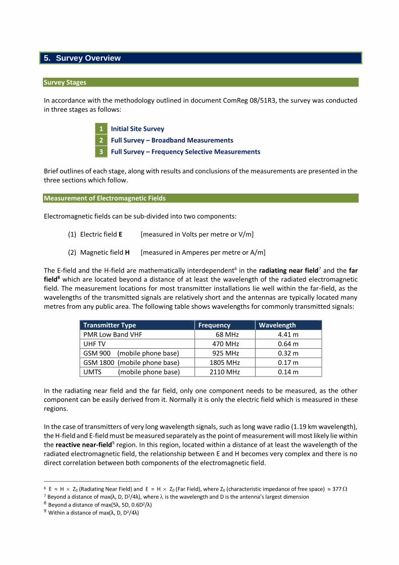
The E-field and the H-field are mathematically interdependent6 in the radiating near field7 and the far field8 which are located beyond a distance of at least the wavelength of the radiated electromagnetic field. The measurement locations for most transmitter installations lie well within the far-field, as the wavelengths of the transmitted signals are relatively short and the antennas are typically located many metres from any public area. The following table shows wavelengths for commonly transmitted signals:
Transmitter Type Frequency Wavelength
PMR Low Band VHF 68 MHz 4.41 m
UHF TV 470 MHz 0.64 m
GSM 900 (mobile phone base) 925 MHz 0.32 m
GSM 1800 (mobile phone base) 1805 MHz 0.17 m
UMTS (mobile phone base) 2110 MHz 0.14 m
In the radiating near field and the far field, only one component needs to be measured, as the other component can be easily derived from it. Normally it is only the electric field which is measured in these regions. In the case of transmitters of very long wavelength signals, such as long wave radio (1.19 km wavelength), the H-field and E-field must be measured separately as the point of measurement will most likely lie within the reactive near-field9 region. In this region, located within a distance of at least the wavelength of the radiated electromagnetic field, the relationship between E and H becomes very complex and there is no direct correlation between both components of the electromagnetic field.
6 E ≈ H Z0 (Radiating Near Field) and E = H Z0 (Far Field), where Z0 (characteristic impedance of free space) 377 7 Beyond a distance of max(λ, D, D2/4λ), where is the wavelength and D is the antenna’s largest dimension 8 Beyond a distance of max(5λ, 5D, 0.6D2/λ) 9 Within a distance of max(λ, D, D2/4λ)
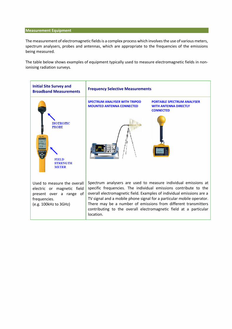
Measurement Equipment The measurement of electromagnetic fields is a complex process which involves the use of various meters, spectrum analysers, probes and antennas, which are appropriate to the frequencies of the emissions being measured. The table below shows examples of equipment typically used to measure electromagnetic fields in non-ionising radiation surveys.
Initial Site Survey and Broadband Measurements
Frequency Selective Measurements
Used to measure the overall electric or magnetic field present over a range of frequencies. (e.g. 100kHz to 3GHz)
SPECTRUM ANALYSER WITH TRIPOD MOUNTED ANTENNA CONNECTED
PORTABLE SPECTRUM ANALYSER WITH ANTENNA DIRECTLY CONNECTED
Spectrum analysers are used to measure individual emissions at specific frequencies. The individual emissions contribute to the overall electromagnetic field. Examples of individual emissions are a TV signal and a mobile phone signal for a particular mobile operator. There may be a number of emissions from different transmitters contributing to the overall electromagnetic field at a particular location.

6. Initial Site Survey
An initial survey was carried out in the area around the designated transmitter site in order to determine the point of maximum non-ionising radiation (NIR). This is the location at which the overall electric field strength level measured was somewhat higher than that measured in all other areas around the site and represents the highest level of exposure to which a member of the general public might be subjected in the vicinity of the transmitter. For this initial survey a calibrated field strength meter fitted with a 3 GHz isotropic probe was used. The meter and probe were used to measure the sum of all electrical fields present at all frequencies from 100 kHz up to 3 GHz. Once the point of maximum NIR was determined, broadband and frequency selective measurements were conducted at that location (see following two sections). For the duration of those measurements, the various instruments, antennas and probes used were mounted on non-metallic supports.

7. Full Survey – Broadband Measurements
The purpose of these measurements was to get an overview of the intensity of the electromagnetic field present at the point of maximum NIR near the site. There, the field strength meter was mounted on a tripod and, fitted with a 3GHz isotropic probe, was set to record, over a six minute period, simultaneous measurements of the sum of all received signals within the frequency range of the probe. This measurement was then repeated using a 60 GHz isotropic probe. The broadband measurement results presented below show the levels in Volts per metre (V/m) recorded in the course of the six minute measurement. The average and maximum levels can be compared to the lowest maximum ICNIRP general public guideline limit which is 28 V/m. If a broadband measurement is higher than 28 V/m, it does not necessarily follow that the ICNIRP Limits have been exceeded, as the limits are frequency dependent. For example, if the emissions are in the 2100 MHz UMTS mobile phone frequency band, then the limit which applies is higher at 61 V/m. A more detailed investigation involving frequency selective measurement is necessary to assess compliance with the ICNIRP Limits (see next section).
Electric field strengths recorded over 6 min period using 3 GHz probe at point of max NIR:
Acquisition Mode: 1 Sec. Sampling
Mean Measurement V/m: 2.89 V/m Peak Measurement V/m: 3.19 V/m
Date: 22/03/2019 Start Time: 10:43
Meter: NBM-550 Probe: EF3091
Frequency Range: 100 kHz – 3 GHz
0
1
2
3
4
5
6
7
8
9
10
0 50 100 150 200 250 300 350
Leve
l (V
/m)
Time (secs)

Electric field strengths recorded over 6 min period using 60 GHz probe at point of max NIR:
Acquisition Mode: 1 Sec. Sampling
Mean Measurement V/m: 2.91 V/m Peak Measurement V/m: 3.41 V/m
Date: 22/03/2019 Start Time: 10:50
Meter: NBM-550 Probe: EF 6091
Frequency Range: 100 MHz – 60 GHz
Conclusion of the Broadband Measurements
The mean and peak measurements were below the lowest ICNIRP guideline limit of 28 V/m.
0
1
2
3
4
5
6
7
8
9
10
0 50 100 150 200 250 300 350
Leve
l (V
/m)
Time (secs)
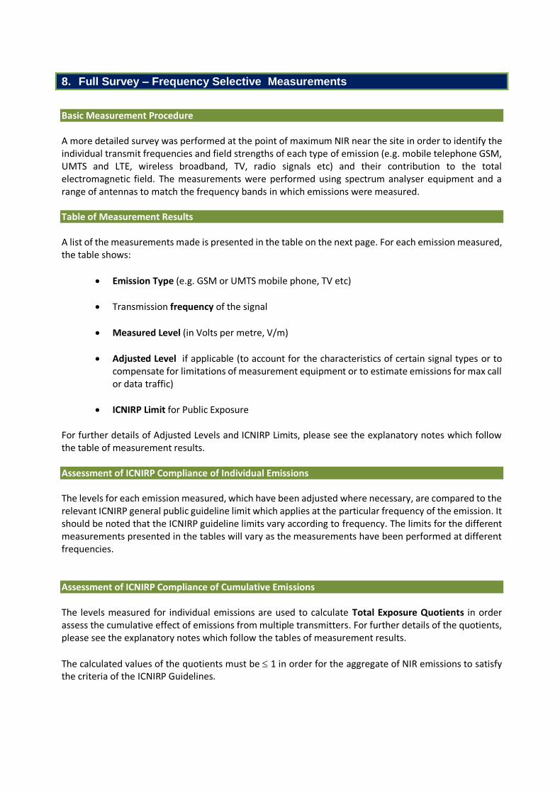
8. Full Survey – Frequency Selective Measurements
Basic Measurement Procedure A more detailed survey was performed at the point of maximum NIR near the site in order to identify the individual transmit frequencies and field strengths of each type of emission (e.g. mobile telephone GSM, UMTS and LTE, wireless broadband, TV, radio signals etc) and their contribution to the total electromagnetic field. The measurements were performed using spectrum analyser equipment and a range of antennas to match the frequency bands in which emissions were measured. Table of Measurement Results A list of the measurements made is presented in the table on the next page. For each emission measured, the table shows:
Emission Type (e.g. GSM or UMTS mobile phone, TV etc)
Transmission frequency of the signal
Measured Level (in Volts per metre, V/m)
Adjusted Level if applicable (to account for the characteristics of certain signal types or to compensate for limitations of measurement equipment or to estimate emissions for max call or data traffic)
ICNIRP Limit for Public Exposure For further details of Adjusted Levels and ICNIRP Limits, please see the explanatory notes which follow the table of measurement results.
Assessment of ICNIRP Compliance of Individual Emissions The levels for each emission measured, which have been adjusted where necessary, are compared to the relevant ICNIRP general public guideline limit which applies at the particular frequency of the emission. It should be noted that the ICNIRP guideline limits vary according to frequency. The limits for the different measurements presented in the tables will vary as the measurements have been performed at different frequencies. Assessment of ICNIRP Compliance of Cumulative Emissions The levels measured for individual emissions are used to calculate Total Exposure Quotients in order assess the cumulative effect of emissions from multiple transmitters. For further details of the quotients, please see the explanatory notes which follow the tables of measurement results.
The calculated values of the quotients must be 1 in order for the aggregate of NIR emissions to satisfy the criteria of the ICNIRP Guidelines.
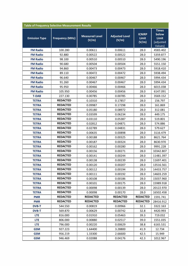
Table of Frequency Selective Measurement Results
Emission Type Frequency (MHz) Measured Level
(V/m) Adjusted Level
(V/m)
ICNIRP Limit (V/m)
Times below Limit
[adjusted Values]
FM Radio 100.280 0.00611 0.00611 28.0 4583.402
FM Radio 92.880 0.00522 0.00522 28.0 5359.877
FM Radio 98.100 0.00510 0.00510 28.0 5490.196
FM Radio 90.680 0.00504 0.00504 28.0 5551.150
FM Radio 94.860 0.00473 0.00473 28.0 5918.410
FM Radio 89.110 0.00472 0.00472 28.0 5938.494
FM Radio 96.640 0.00467 0.00467 28.0 5994.434
FM Radio 91.260 0.00467 0.00467 28.0 5994.434
FM Radio 95.950 0.00466 0.00466 28.0 6015.038
FM Radio 105.950 0.00456 0.00456 28.0 6147.091
T-DAB 227.130 0.00785 0.00785 28.0 3569.152
TETRA REDACTED 0.10310 0.17857 28.0 156.797
TETRA REDACTED 0.09987 0.17298 28.0 161.869
TETRA REDACTED 0.05180 0.08972 28.0 312.081
TETRA REDACTED 0.03599 0.06234 28.0 449.175
TETRA REDACTED 0.03110 0.05387 28.0 519.801
TETRA REDACTED 0.02812 0.04871 28.0 574.886
TETRA REDACTED 0.02789 0.04831 28.0 579.627
TETRA REDACTED 0.00635 0.00898 28.0 3116.479
TETRA REDACTED 0.00188 0.00325 28.0 8621.764
TETRA REDACTED 0.00187 0.00324 28.0 8630.970
TETRA REDACTED 0.00162 0.00280 28.0 9991.228
TETRA REDACTED 0.00156 0.00271 28.0 10342.807
TETRA REDACTED 0.00141 0.00244 28.0 11481.397
TETRA REDACTED 0.00138 0.00239 28.0 11697.401
TETRA REDACTED 0.00120 0.00207 28.0 13516.561
TETRA REDACTED 0.00112 0.00194 28.0 14433.757
TETRA REDACTED 0.00111 0.00192 28.0 14603.259
TETRA REDACTED 0.00108 0.00186 28.0 15037.960
TETRA REDACTED 0.00101 0.00175 28.0 15989.918
TETRA REDACTED 0.00098 0.00139 28.0 20122.970
TETRA REDACTED 0.00098 0.00170 28.0 16502.458
PMR REDACTED REDACTED REDACTED REDACTED 1591.741
PMR REDACTED REDACTED REDACTED REDACTED 28416.912
DVB-T 544.550 0.00819 0.00966 32.1 3322.163
DVB-T 569.870 0.00629 0.00742 32.8 4420.993
LTE 816.000 0.01910 0.05463 39.3 719.032
LTE 806.000 0.00880 0.02517 39.0 1551.035
LTE 796.000 0.00220 0.00629 38.8 6165.531
GSM 927.223 1.64400 3.28800 41.9 12.734
GSM 956.219 1.33300 2.66600 42.5 15.949
GSM 946.469 0.02088 0.04176 42.3 1012.967

UMTS FDD 932.500 0.99090 3.70034 42.0 11.347
UMTS FDD 937.000 0.81790 3.05430 42.1 13.780
UMTS FDD 943.000 0.78780 2.94190 42.2 14.353
UMTS FDD 953.500 0.37460 1.39888 42.5 30.352
GSM 1841.600 1.55700 3.11400 59.0 18.949
LTE 1815.000 0.69180 2.42355 58.6 24.171
LTE 1830.000 1.10000 4.44972 58.8 13.219
LTE 1855.000 0.61310 2.48011 59.2 23.878
LTE 1875.000 0.49640 1.73901 59.5 34.237
UMTS FDD 2112.500 0.48440 1.53182 61.0 39.822
UMTS FDD 2152.500 0.32930 1.04135 61.0 58.578
UMTS FDD 2147.500 0.30380 0.96071 61.0 63.495
UMTS FDD 2117.500 0.25690 0.81239 61.0 75.087
UMTS FDD 2132.500 0.22050 0.69729 61.0 87.482
UMTS FDD 2122.500 0.20940 0.66219 61.0 92.119
UMTS FDD 2127.500 0.20210 0.63910 61.0 95.447
UMTS FDD 2157.500 0.19300 0.61032 61.0 99.947
WiFi 2447.500 0.26700 0.43438 61.0 140.429
WiFi 2425.000 0.20020 0.32571 61.0 187.286
WiFi 2465.000 0.18850 0.30667 61.0 198.910
WiFi 2460.910 0.11580 0.18840 61.0 323.788
WiFi 2432.500 0.08225 0.13381 61.0 455.862
WiFi 2475.000 0.04775 0.07768 61.0 785.228
WiFi 2410.000 0.03608 0.05870 61.0 1039.208
WiFi 2414.990 0.02550 0.04149 61.0 1470.377
Total Exposure Quotients [calculated from Adjusted Levels]
Quotient Frequency Range Calculated Quotient Value Limit
Electrical Stimulation Effects 1 Hz to 10 MHz n/a 1
Thermal Effects 100 kHz and above 0.043933 1
Overall Conclusions of the Survey
Frequency Selective Measurements: (Individual emissions measured at specific frequencies)
Below ICNIRP Public Limits (Compliant)
Total Exposure Quotient: (Assessment of cumulative emissions from multiple transmitters)
Below ICNIRP Public Limits (Compliant)
Explanatory Notes
Adjusted Levels For some emissions an adjusted level has been calculated from the measured level for any or both of the following reasons:
(1) To compensate for the limited measurement resolution of the spectrum analyser. For example, a measurement of a DVB-T (digital television) signal performed with at a resolution of 5 MHz needs to be adjusted upwards using a correction factor in order to account for the energy present within the full 7.61 MHz bandwidth of the signal.
(2) To extrapolate to an estimate of the level under maximum traffic or duty cycle from the transmitter. For example, the base stations of mobile telephone networks produce emissions which vary according to the changing volume of calls or data traffic over the course of the day.
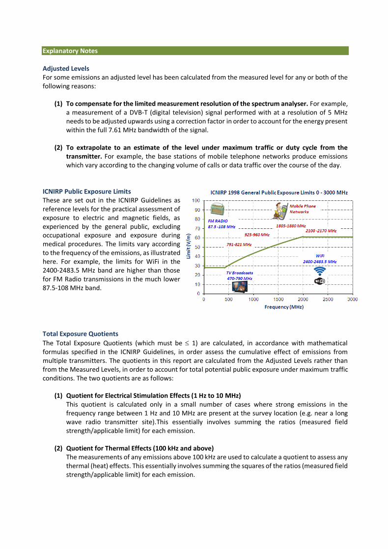
ICNIRP Public Exposure Limits These are set out in the ICNIRP Guidelines as reference levels for the practical assessment of exposure to electric and magnetic fields, as experienced by the general public, excluding occupational exposure and exposure during medical procedures. The limits vary according to the frequency of the emissions, as illustrated here. For example, the limits for WiFi in the 2400-2483.5 MHz band are higher than those for FM Radio transmissions in the much lower 87.5-108 MHz band.
Total Exposure Quotients
The Total Exposure Quotients (which must be 1) are calculated, in accordance with mathematical formulas specified in the ICNIRP Guidelines, in order assess the cumulative effect of emissions from multiple transmitters. The quotients in this report are calculated from the Adjusted Levels rather than from the Measured Levels, in order to account for total potential public exposure under maximum traffic conditions. The two quotients are as follows:
(1) Quotient for Electrical Stimulation Effects (1 Hz to 10 MHz) This quotient is calculated only in a small number of cases where strong emissions in the frequency range between 1 Hz and 10 MHz are present at the survey location (e.g. near a long wave radio transmitter site).This essentially involves summing the ratios (measured field strength/applicable limit) for each emission.
(2) Quotient for Thermal Effects (100 kHz and above)
The measurements of any emissions above 100 kHz are used to calculate a quotient to assess any thermal (heat) effects. This essentially involves summing the squares of the ratios (measured field strength/applicable limit) for each emission.