1 Short Summary of the Mechanics of Wind Turbine Korn Saran-Yasoontorn Department of Civil...
28
1 Short Summary of the Mechanics of Wind Turbine Korn Saran-Yasoontorn Department of Civil Engineering University of Texas at Austin 8/7/02
-
Upload
brenda-davidson -
Category
Documents
-
view
216 -
download
2
Transcript of 1 Short Summary of the Mechanics of Wind Turbine Korn Saran-Yasoontorn Department of Civil...
1
Short Summary of the Mechanics of Wind Turbine
Korn Saran-Yasoontorn
Department of Civil EngineeringUniversity of Texas at Austin
8/7/02

2
Summarized from
Wind energy explained: theory, design and application./ Manwell, J. F. / Chichester / 2002
Wind turbine technology: fundamental concepts of wind turbine engineering. / New York / 1994
Wind energy conversion systems/ Freris, L.L./ Prentice Hall/ 1990
Wind turbine engineering design/ Eggleston, D.M. and Stoddard, F.S./ New York/ 1987
Introduction to wind turbine engineering/ Wortman, A.J./ Butterworth Publishers/ 1983
3
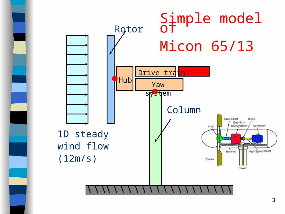
Yaw system
HubDrive train
Column
RotorSimple model ofMicon 65/13
1D steady wind flow(12m/s)
4
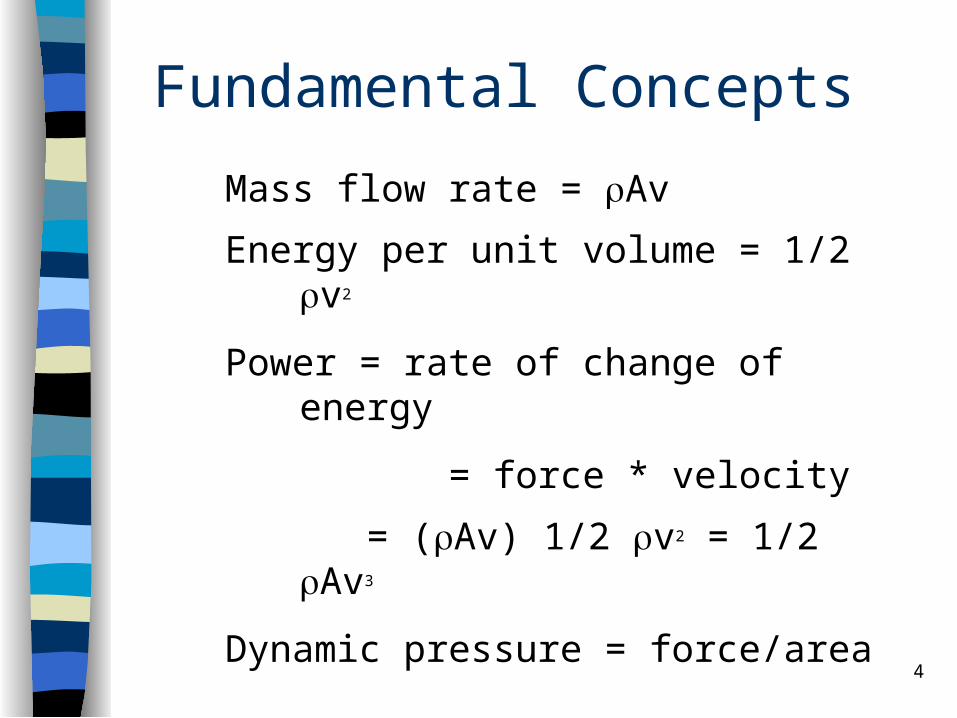
Fundamental Concepts
Mass flow rate = Av
Energy per unit volume = 1/2 v2
Power = rate of change of energy
= force * velocity
= (Av) 1/2 v2 = 1/2 Av3
Dynamic pressure = force/area
= power/vA
=1/2 v2

5
Actuator Disk Model with no wake rotation
U1U2 U3 U4
rotor disk
Assumptions:
i. Homogeneous, incompressible, steady wind
ii. Uniform flow velocity at disk (uniform thrust)
iii. Homogenous disk
iv. Non-rotating disk
stream tube boundary
upstream
downstream

6
)(
)(
41
14
uumT
uumT
dt
dpF
Conservation of Linear Momentum
where T is the thrust acting uniformly on the disk (rotor) which can be written as a function of the change of pressure as follow
)( 32 ppAT

7
244
233
222
211
2
1
2
12
1
2
1
upup
upup
)]1(4[2
1 21 aaAuT
Bernoulli’s Equation (energy conserved)
Relate above equations and define the axial induction factor, a as
1
21 )(
u
uua
we obtain
8
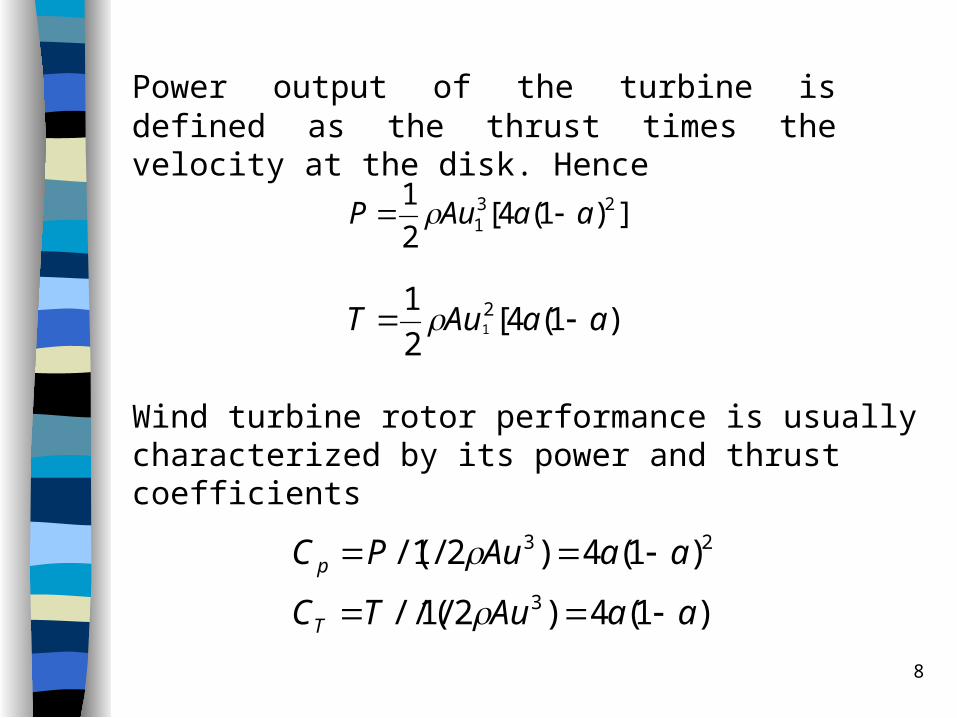
Power output of the turbine is defined as the thrust times the velocity at the disk. Hence
])1(4[2
1 231 aaAuP
)1(4)2/1//(
)1(4)2/1/(3
23
aaAuTC
aaAuPC
T
p
)]1(4[2
1 21 aaAuT
Wind turbine rotor performance is usually characterized by its power and thrust coefficients
9
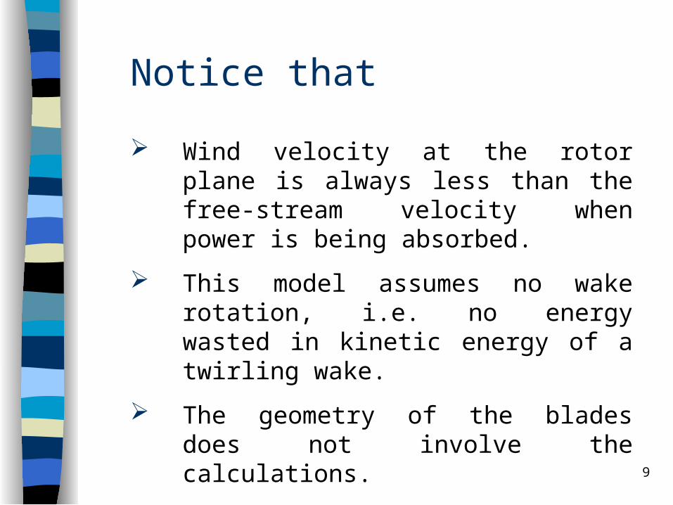
Notice that
Wind velocity at the rotor plane is always less than the free-stream velocity when power is being absorbed.
This model assumes no wake rotation, i.e. no energy wasted in kinetic energy of a twirling wake.
The geometry of the blades does not involve the calculations.
10
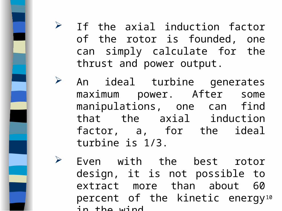
If the axial induction factor of the rotor is founded, one can simply calculate for the thrust and power output.
An ideal turbine generates maximum power. After some manipulations, one can find that the axial induction factor, a, for the ideal turbine is 1/3.
Even with the best rotor design, it is not possible to extract more than about 60 percent of the kinetic energy in the wind
11
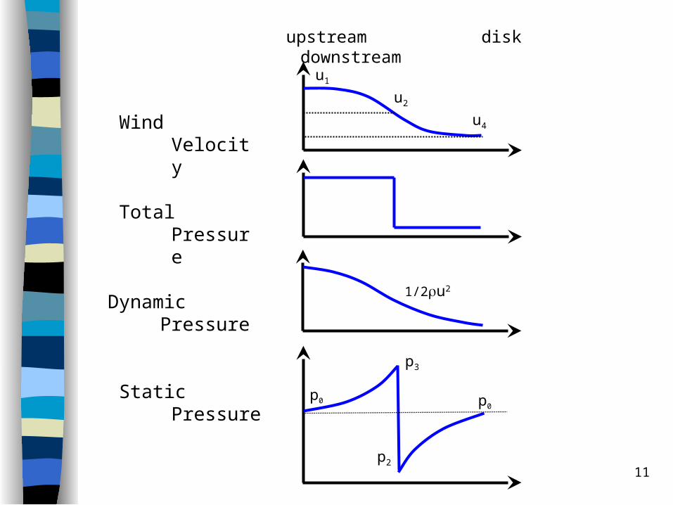
Wind Velocity
Total Pressure
Dynamic Pressure
Static Pressure
p3
p2
upstream disk downstream
u1
u2
u4
1/2u2
p0 p0

12
Actuator Disk Model with wake rotation
U1U2 U3 U4
rotor disk
U
U(1-2a)U(1-a)
dr
r
The thrust distribution is circumferentially uniform.(infinite number of blades)
13
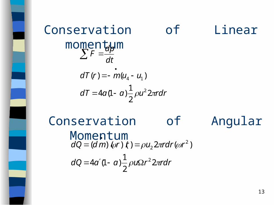
Conservation of Linear momentum
rdruaadT
uumrdT
dt
dpF
22
1)1(4
)()(
2
14
Conservation of Angular Momentum
rdrruaadQ
rrdrurrmddQ
22
1)1(4
)(2))()((
2
22
14
rdrrdAppdT
rpp
2])2
1([)(
)2
1()(
232
232
2
a
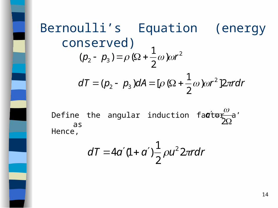
Bernoulli’s Equation (energy conserved)
Define the angular induction factor a’ as
rdruaadT 22
1)1(4 2
Hence,

15
uRRrr ,/
2
)1(
)1(raa
aa
Equating the thrust on an annular element derived from the conservation of linear momentum and the Bernoulli’s equation gives
where
For an ideal turbine that produces maximum power output,
14
31
a
aa
16
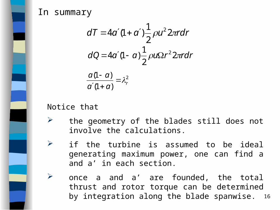
In summary
rdruaadT 22
1)1(4 2
rdrruaadQ 22
1)1(4 2
2
)1(
)1(raa
aa
Notice that
the geometry of the blades still does not involve the calculations.
if the turbine is assumed to be ideal generating maximum power, one can find a and a’ in each section.
once a and a’ are founded, the total thrust and rotor torque can be determined by integration along the blade spanwise.
17
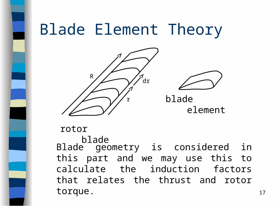
Blade Element Theory
Blade geometry is considered in this part and we may use this to calculate the induction factors that relates the thrust and rotor torque.
blade elementr
dr
rotor blade
R

18
Lift and Drag Forces
u
Ωr
urel
FL
FD
)2
1(
)2
1(
2
2
relDD
relLL
AuCF
AuCF
Note that CL and CD vary with cross section
(top view)

19
Typical Variation of Aerofoil Coefficients
Val
ues
of
Co
effi
cien
ts
-10 0 90angle of attack (degrees)
Cl
Cd
1.0
0.5
0.0
flow separation
20
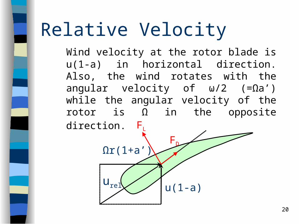
Relative Velocity
u(1-a)
Ωr(1+a’)
urel
FL
FD
Wind velocity at the rotor blade is u(1-a) in horizontal direction. Also, the wind rotates with the angular velocity of ω/2 (=Ωa’) while the angular velocity of the rotor is Ω in the opposite direction.
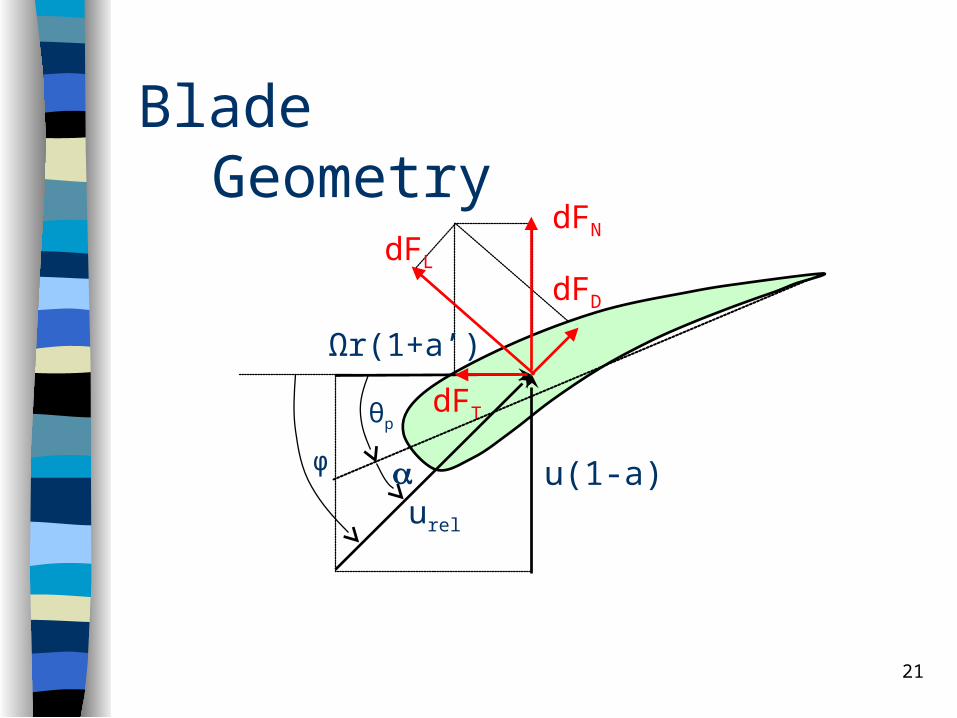
21
u(1-a)
Ωr(1+a’)
urel
dFL
dFD
dFN
dFTθp
φ
Blade Geometry
22
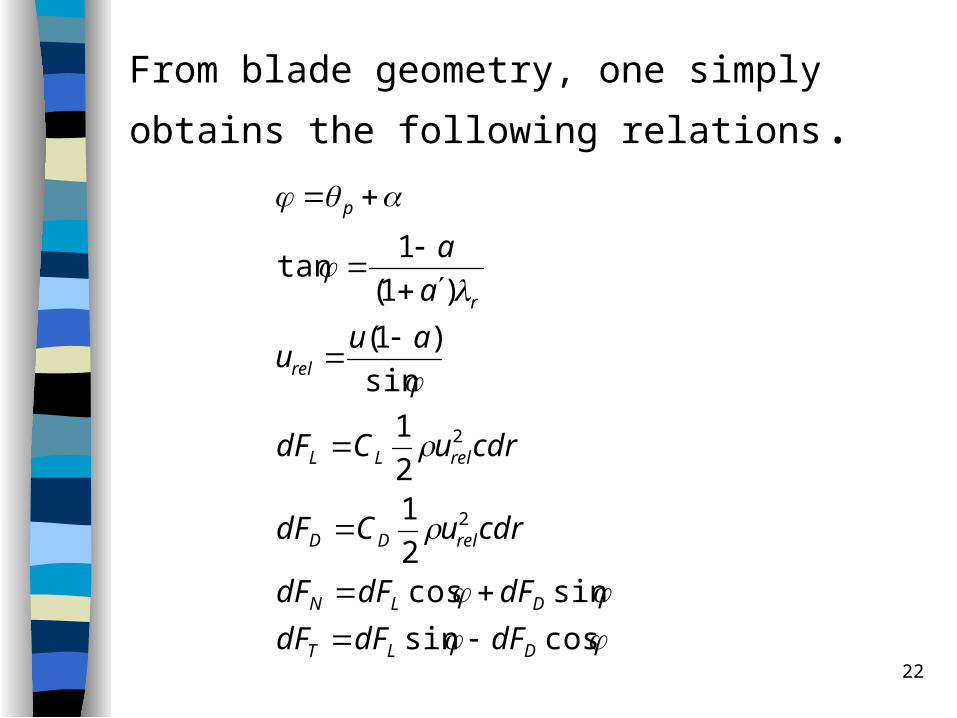
From blade geometry, one simply obtains
the following relations.
cossin
sincos2
12
1
sin
)1(
)1(
1tan
2
2
DLT
DLN
relDD
relLL
rel
r
p
dFdFdF
dFdFdF
cdruCdF
cdruCdF
auu
a
a
23
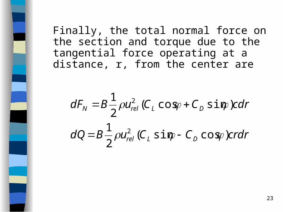
Finally, the total normal force on the section and torque due to the tangential force operating at a distance, r, from the center are
crdrCCuBdQ
cdrCCuBdF
DLrel
DLrelN
)cossin(2
1
)sincos(2
1
2
2

24
Since the forces and moments derived from momentum theory (actuator model) and blade element theory must be equal,
crdrCCuBdrruaadQ
cdrCCuBrdraaudT
DLrel
DLrel
)cossin(2
1)1(4
)sincos(2
1)1(4
23
22
from momentum theory blade element theory

25
)cos(sin
)sin(cos2sin4
r
rL Bc
rC
One can solve for C and α at each section by using this equation and the empirical C vs α curves. Once both parameters are known, a and a’ at the section can be determined from
)sin8/()1(
)sin8/(cos)1( 2
rL
L
rBcCaa
rBcCaa
26
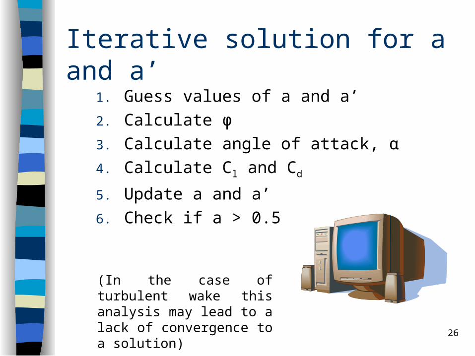
Iterative solution for a and a’
1. Guess values of a and a’2. Calculate φ3. Calculate angle of attack, α4. Calculate Cl and Cd
5. Update a and a’6. Check if a > 0.5
(In the case of turbulent wake this analysis may lead to a lack of convergence to a solution)
27
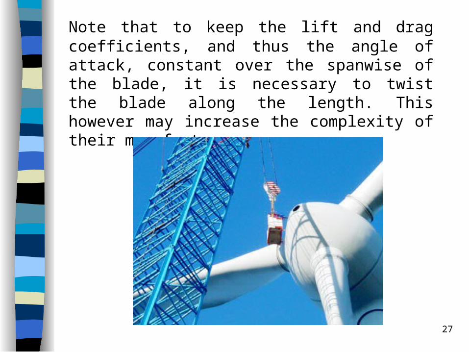
Note that to keep the lift and drag coefficients, and thus the angle of attack, constant over the spanwise of the blade, it is necessary to twist the blade along the length. This however may increase the complexity of their manufacture.

28
Tip loss factor
The tip loss factor allows for the velocities and forces not being circumferentially uniform due to the rotor having a finite number of blades. The Prandtl tip loss factor can be express as
)115.0arccos(exp)/2( 2
B
R
rF