1 Electrical Engineering BA (B), Analog Electronics, Lecture 2 ET065G 6 Credits ET064G 7.5 Credits...
34
1 Electrical Engineering BA (B), Analog Electronics, Lecture 2 ET065G 6 Credits ET064G 7.5 Credits Muhammad Amir Yousaf
-
Upload
felicia-adams -
Category
Documents
-
view
216 -
download
0
Transcript of 1 Electrical Engineering BA (B), Analog Electronics, Lecture 2 ET065G 6 Credits ET064G 7.5 Credits...

Muhammad Amir Yousaf
1
Electrical Engineering BA (B), Analog Electronics,
Lecture 2
ET065G 6 CreditsET064G 7.5 Credits

Muhammad Amir Yousaf
Frequency Response of R,L,C
How varying frequency affects the opposition offered by R,L and C
2

Muhammad Amir Yousaf
Impedance Diagram
3

Muhammad Amir Yousaf
Impedance Diagram
The resistance appears on the positive real axis, the inductive reactance on the positive imaginary axis, and the capacitive reactance on the negative imaginary axis.
Circuits combining different types of elements will have total impedances that extend from 90° to -90°
4

Muhammad Amir Yousaf
AC Circuit Analysis
5

Muhammad Amir Yousaf
Complex Numbers
• A complex number represents a point in a two-dimensional plane located with reference to two distinct axes.
• This point can also determine a radius vector drawn from the origin to the point.
6

Muhammad Amir Yousaf
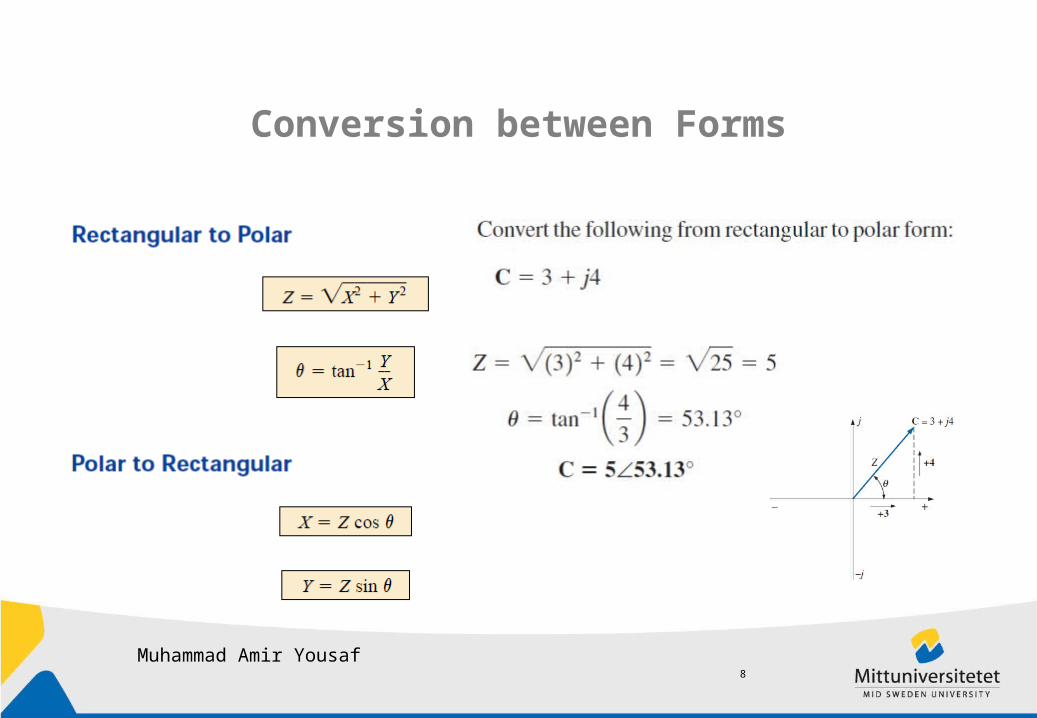
Complex Numbers
Rectangular and Polar forms
Rectangular Form
Polar Form
7
Muhammad Amir Yousaf
Conversion between Forms
8
Muhammad Amir Yousaf
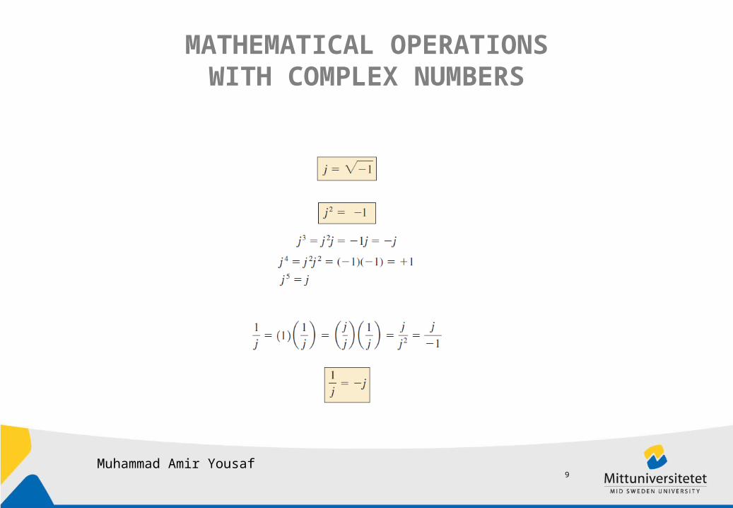
MATHEMATICAL OPERATIONSWITH COMPLEX NUMBERS
9

Muhammad Amir Yousaf
MATHEMATICAL OPERATIONSWITH COMPLEX NUMBERS
Complex Conjugate
simply changing the sign of the imaginary part
10

Muhammad Amir Yousaf
MATHEMATICAL OPERATIONSWITH COMPLEX NUMBERS
Reciprocal
11

Muhammad Amir Yousaf
MATHEMATICAL OPERATIONSWITH COMPLEX NUMBERS
Addition Subtraction
Addition or subtraction cannot be performed in polar form unless thecomplex numbers have the same angle u or unless they differ only bymultiples of 180°.
12

Muhammad Amir Yousaf
MATHEMATICAL OPERATIONSWITH COMPLEX NUMBERS
Multiplication Division
13
Muhammad Amir Yousaf
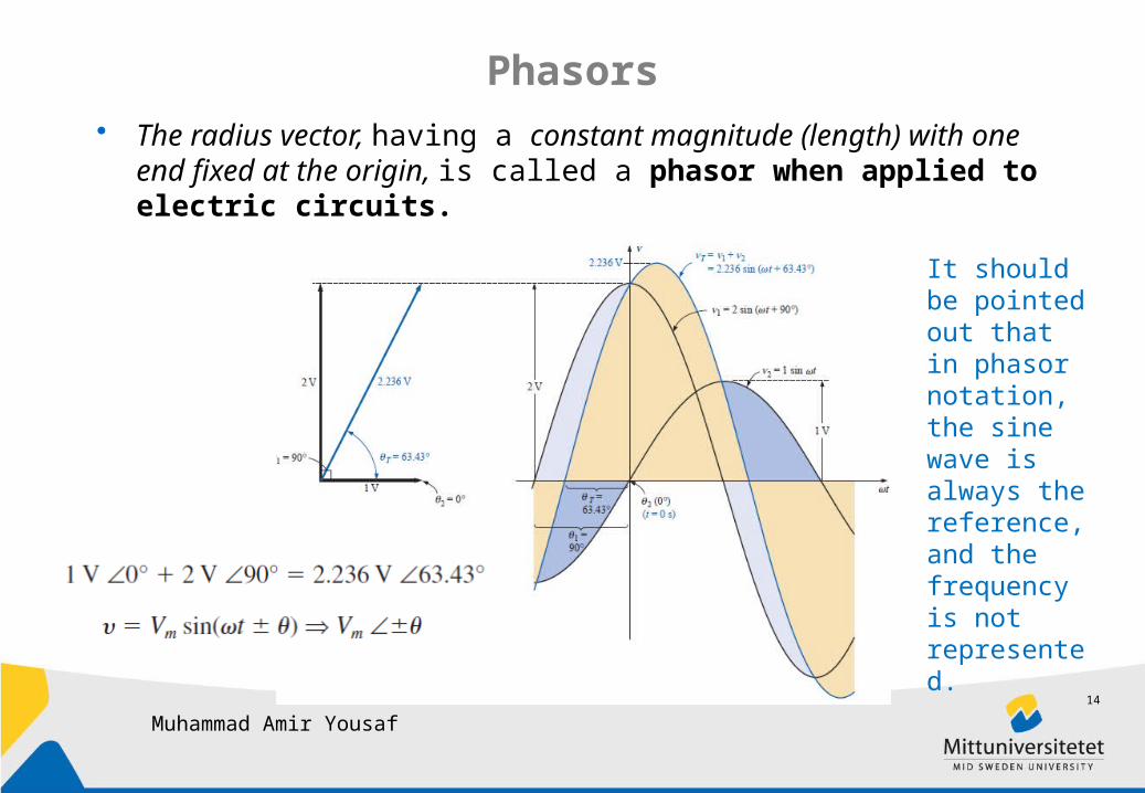
Phasors• The radius vector, having a constant magnitude (length) with one end
fixed at the origin, is called a phasor when applied to electric circuits.
It should be pointed out that in phasor notation, the sine wave is always the reference, and thefrequency is not represented.
14
Muhammad Amir Yousaf
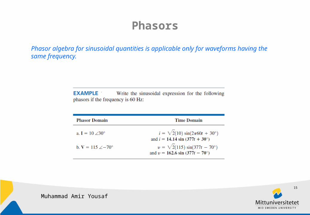
Phasors
Phasor algebra for sinusoidal quantities is applicable only for waveforms having the same frequency.
15

Muhammad Amir Yousaf
R,L,C in series
16

Muhammad Amir Yousaf
Voltage Divide Rule
17
Muhammad Amir Yousaf
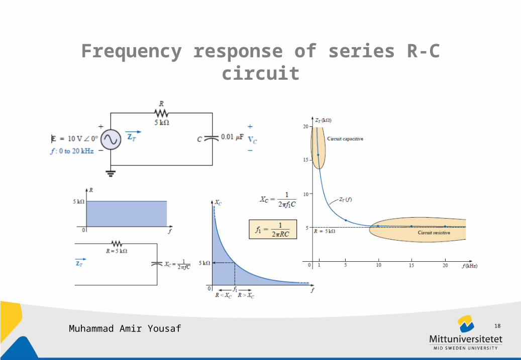
Frequency response of series R-C circuit
18

Muhammad Amir Yousaf
Bode Diagram
• It is a technique for sketching the frequency response of systems (i.e. filter, amplifiers etc) on dB scale . It provides an excellent way to compare decibel levels at different frequencies.
• Absolute decibel value and phase of the transfer function is plotted against a logarithmic frequency axis.
fHangle
fHdB
19

Muhammad Amir Yousaf
Decibel, dB decibel, dB is very useful measure to compare two levels
of power.
It is used for expressing amplification (and attenuation)InVOutV
VAVdBA
InVOutV
InV
OutV
RInV
ROutV
InPOutP
PdBA
R
VIVP
InPOutP
PAPdBA
log20log20
log20
2
log102
2
log10log10
2
log10log10
20

Muhammad Amir Yousaf
Bode Plot for a RC Circuit
21

Muhammad Amir Yousaf
Bode Plot for a RC Circuit
This gives an idealized bode plot.
22

Muhammad Amir Yousaf
Bode Plot for a RC Circuit
Note that as the frequency of interest approaches fc , the dB gain becomes less negative and approaches the final normalized value of 0 dB.
The resulting plot is a straight line intersectingthe 0 dB line at fc . It increases to the right at a rate of 6 dB per octave or 20 dB per decade.
At higher frequencies:
23

Muhammad Amir Yousaf
Bode Plot for a RC Circuit
The phase response can also be sketched using straight-line asymptotes by considering a few critical points in the frequency spectrum.
An asymptote at theta = 90 for f << fc/10, an asymptote at theta = 0 for f >> 10fc and an asymptote from fc/10 to
10fc that passes through theta = 45 at f= fc.
24

Muhammad Amir Yousaf
Bode diagram for multiple stage filter
According to logarithmic laws
dBA
dBA
dBA
dBtotA
AAAtotA
321
321
321 AangleAangleAangletotAangle
25

Muhammad Amir Yousaf
Bode diagram for multiple stage filter
26

Muhammad Amir Yousaf
Bode diagram for multiple stage circuit
27

Muhammad Amir Yousaf
Bode diagram
28

Muhammad Amir Yousaf
Bode diagram
29

Muhammad Amir Yousaf
Exercise
30
Muhammad Amir Yousaf
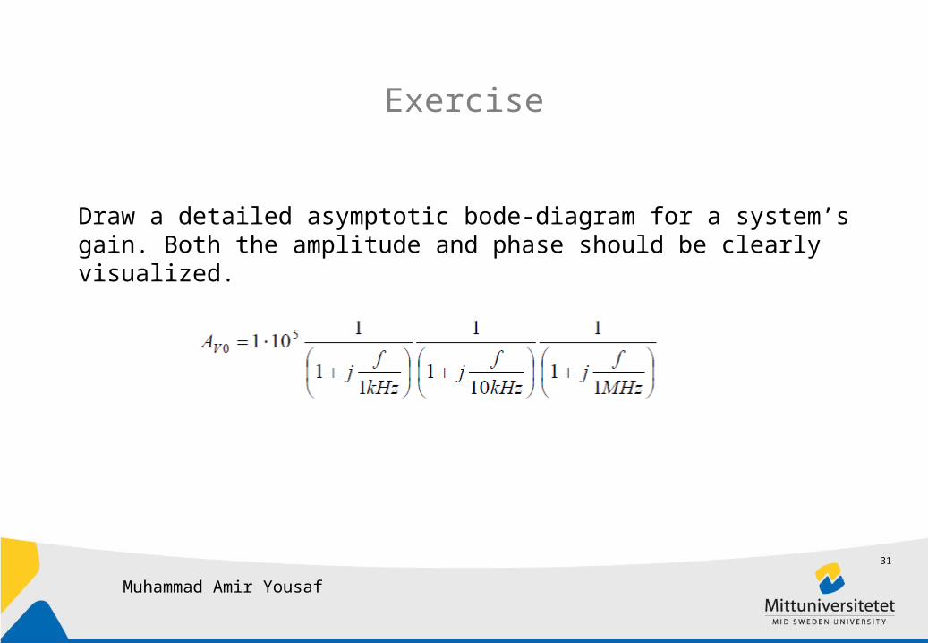
Exercise
Draw a detailed asymptotic bode-diagram for a system’s gain. Both the amplitude and phase should be clearly visualized.
31

Muhammad Amir Yousaf
Exercise
Derive to get Bode plot format equation for the system shown in the figure
fHangle
fHdB
Z1
Z2
Gain = -Z2/Z132

Thank You
Muhammad Amir Yousaf
33

References
• Introductory Circuit Analysis By Boylestad
Muhammad Amir Yousaf
34