1 ECE243 LEGO Autobalance LAB. 2 But first: LOGICAL SHIFTS SLL/SLLI: shift left logical –like...
19
1 ECE243 LEGO Autobalance LAB
-
Upload
arlene-spencer -
Category
Documents
-
view
216 -
download
0
Transcript of 1 ECE243 LEGO Autobalance LAB. 2 But first: LOGICAL SHIFTS SLL/SLLI: shift left logical –like...

1
ECE243
LEGO Autobalance LAB
2
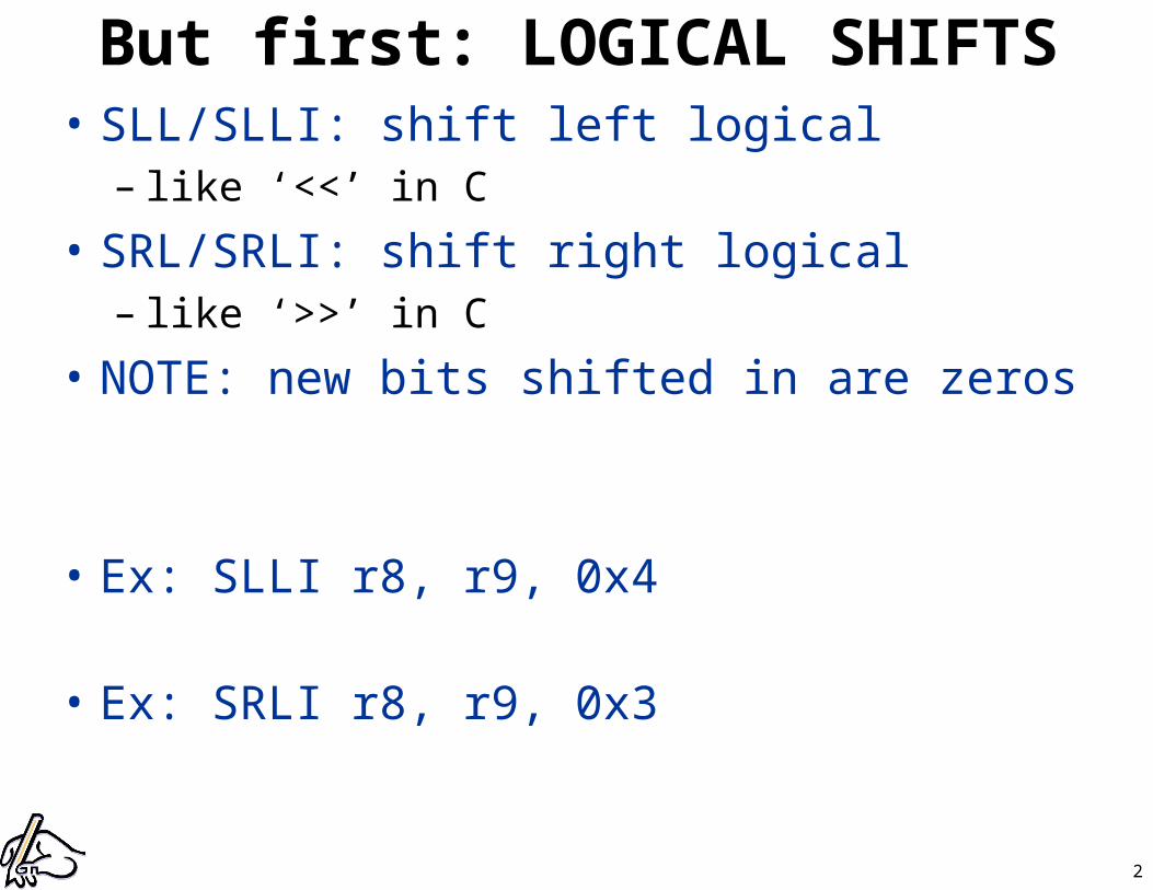
But first: LOGICAL SHIFTS• SLL/SLLI: shift left logical
– like ‘<<’ in C
• SRL/SRLI: shift right logical – like ‘>>’ in C
• NOTE: new bits shifted in are zeros
• Ex: SLLI r8, r9, 0x4
• Ex: SRLI r8, r9, 0x3
3
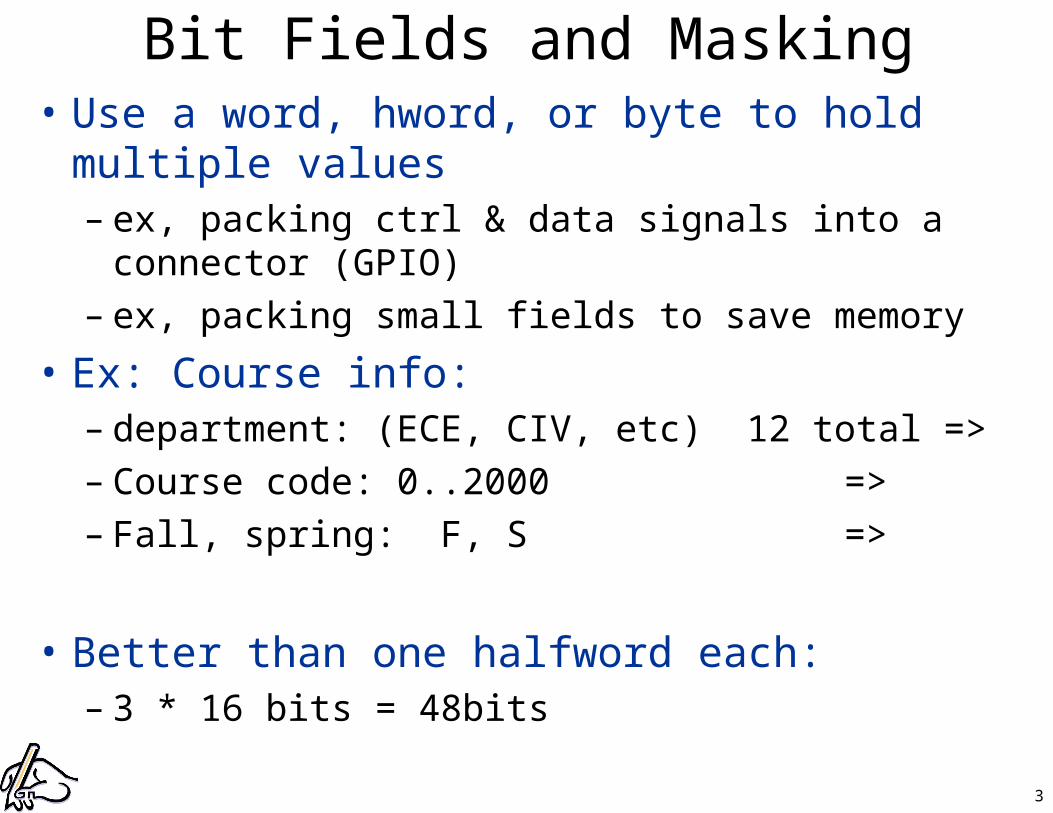
Bit Fields and Masking• Use a word, hword, or byte to hold multiple values
– ex, packing ctrl & data signals into a connector (GPIO)– ex, packing small fields to save memory
• Ex: Course info: – department: (ECE, CIV, etc) 12 total =>– Course code: 0..2000 =>– Fall, spring: F, S =>
• Better than one halfword each: – 3 * 16 bits = 48bits
4
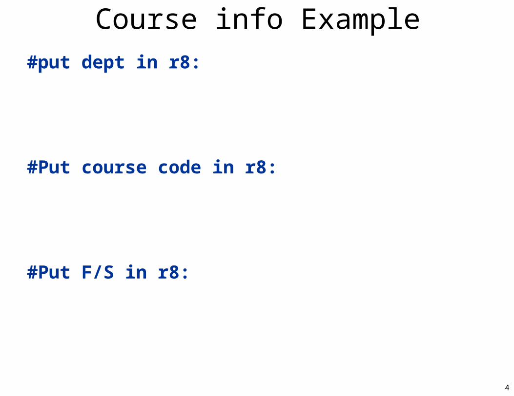
Course info Example#put dept in r8:
#Put course code in r8:
#Put F/S in r8:

5
Next Lab: You will Build a Segway!
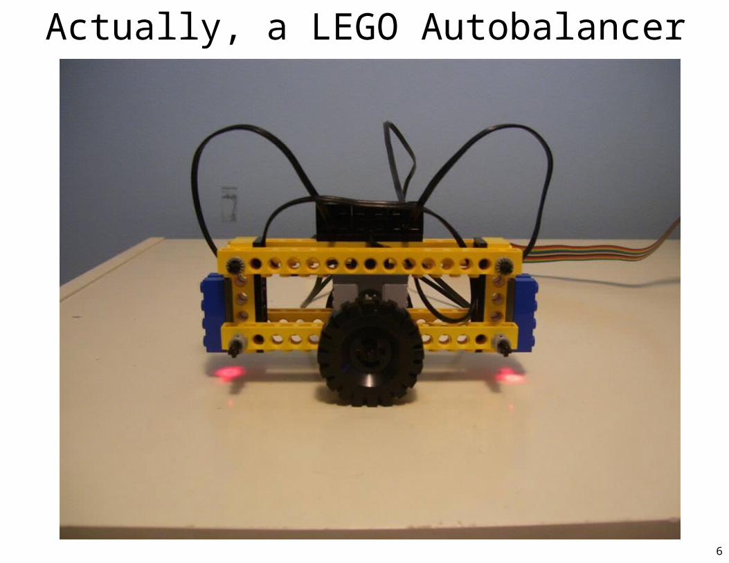
6
Actually, a LEGO Autobalancer
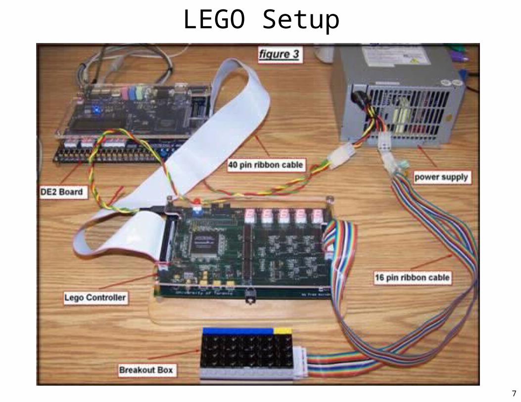
7
LEGO Setup
8
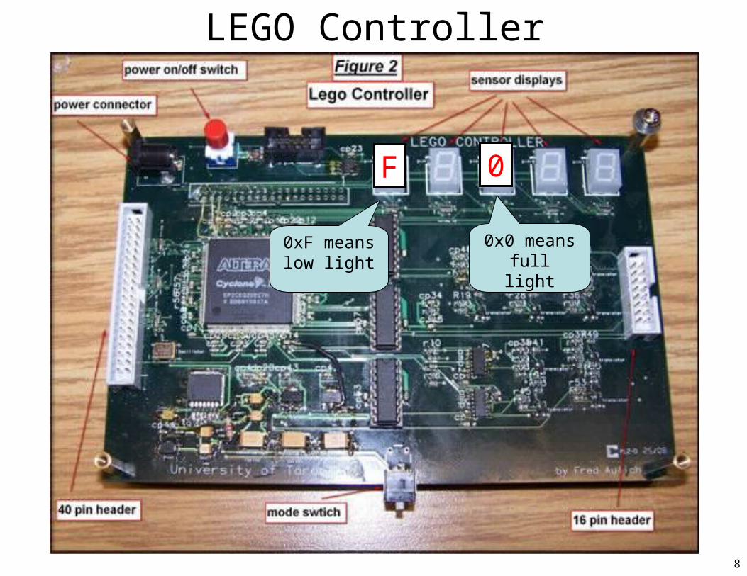
LEGO Controller
0F
0xF means low light
0x0 means full light

9
LEGO Breakout Box

10
Autobalancer with Breakout Box
11
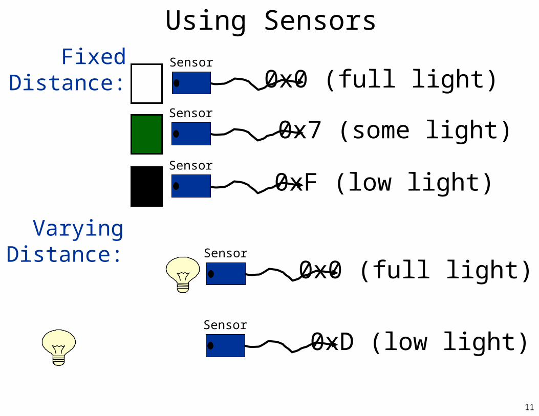
Using SensorsSensor
0x0 (full light)
Sensor
0xF (low light)
Sensor
0x7 (some light)
Sensor
0x0 (full light)
Sensor
0xD (low light)
FixedDistance:
VaryingDistance:
12
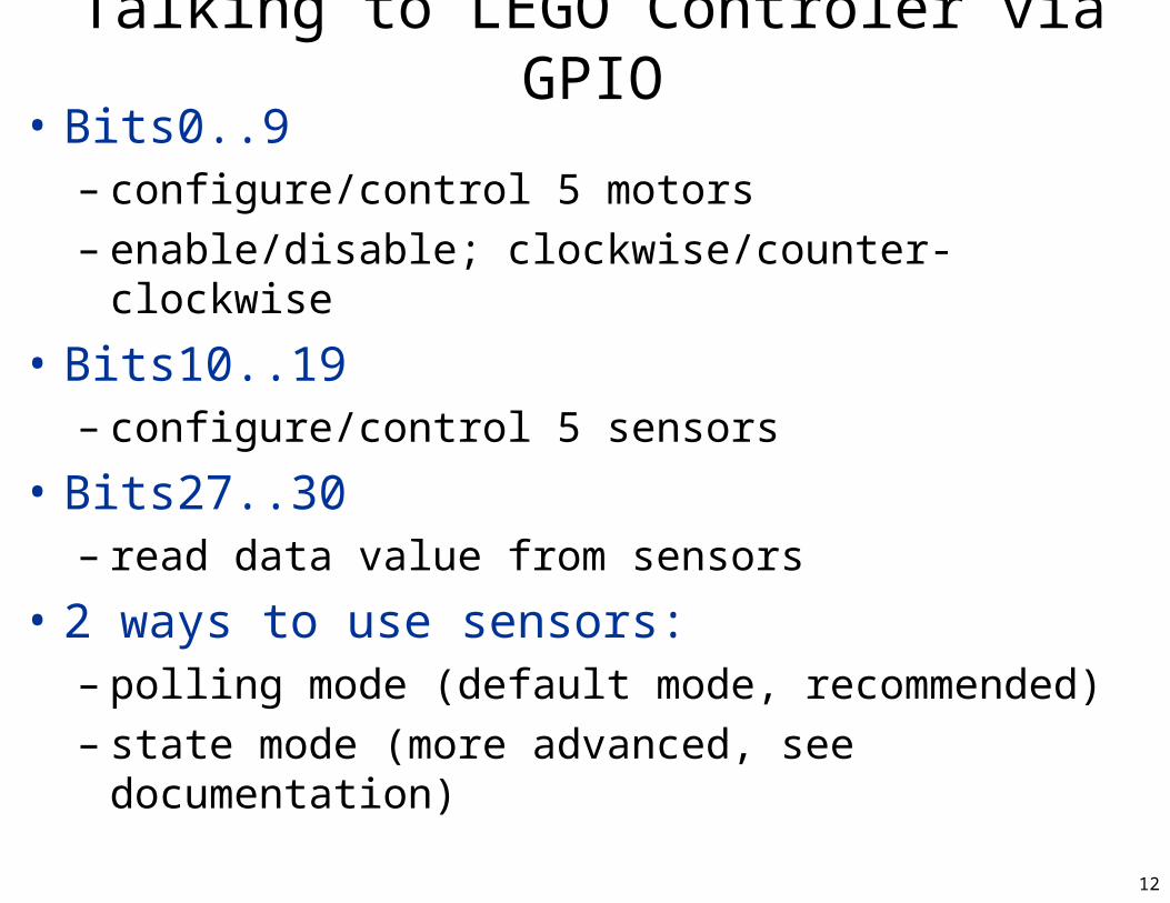
Talking to LEGO Controler via GPIO• Bits0..9
– configure/control 5 motors– enable/disable; clockwise/counter-clockwise
• Bits10..19– configure/control 5 sensors
• Bits27..30– read data value from sensors
• 2 ways to use sensors:– polling mode (default mode, recommended)– state mode (more advanced, see documentation)
13
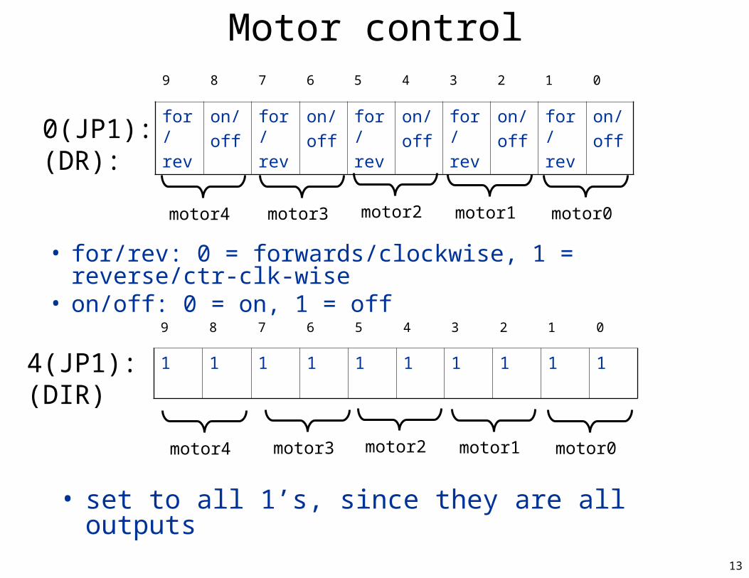
Motor control9 8 7 6 5 4 3 2 1 0
for/
rev
on/
off
for/
rev
on/
off
for/
rev
on/
off
for/
rev
on/
off
for/
rev
on/
off
motor4 motor2 motor1 motor0
• for/rev: 0 = forwards/clockwise, 1 = reverse/ctr-clk-wise• on/off: 0 = on, 1 = off
0(JP1):(DR):
9 8 7 6 5 4 3 2 1 0
1 1 1 1 1 1 1 1 1 1
motor3 motor2 motor1 motor0
4(JP1):(DIR)
• set to all 1’s, since they are all outputs
motor3
motor4
14
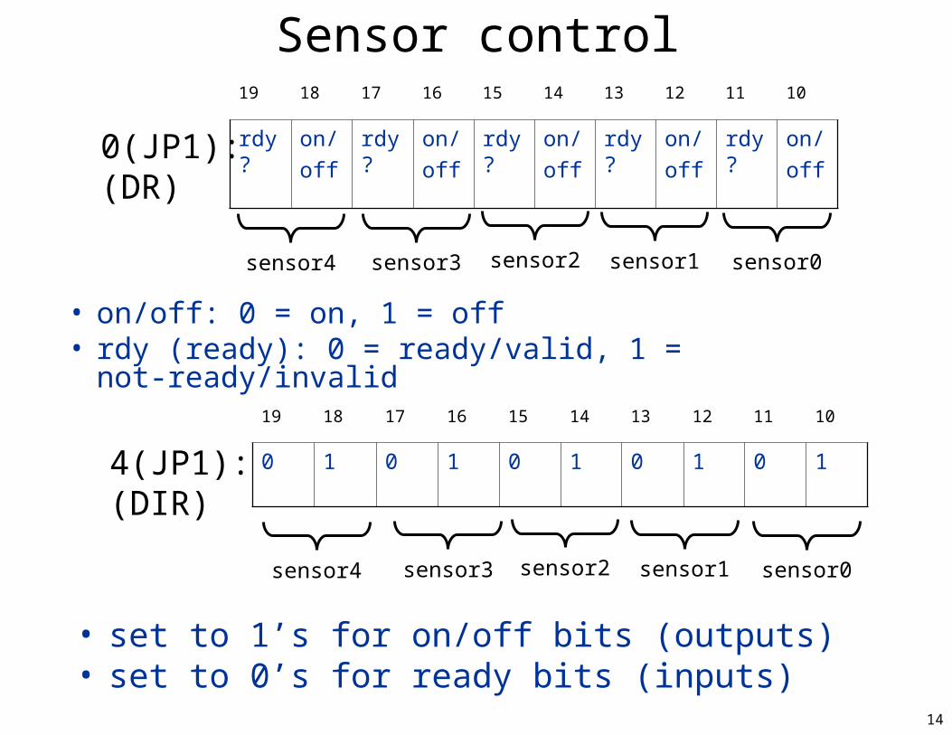
Sensor control
• on/off: 0 = on, 1 = off• rdy (ready): 0 = ready/valid, 1 = not-ready/invalid
0(JP1):(DR)
4(JP1):(DIR)
• set to 1’s for on/off bits (outputs)• set to 0’s for ready bits (inputs)
19 18 17 16 15 14 13 12 11 10
rdy? on/
off
rdy? on/
off
rdy? on/
off
rdy? on/
off
rdy? on/
off
sensor4 sensor2 sensor1 sensor0sensor3
19 18 17 16 15 14 13 12 11 10
0 1 0 1 0 1 0 1 0 1
sensor3 sensor2 sensor1 sensor0sensor4
15
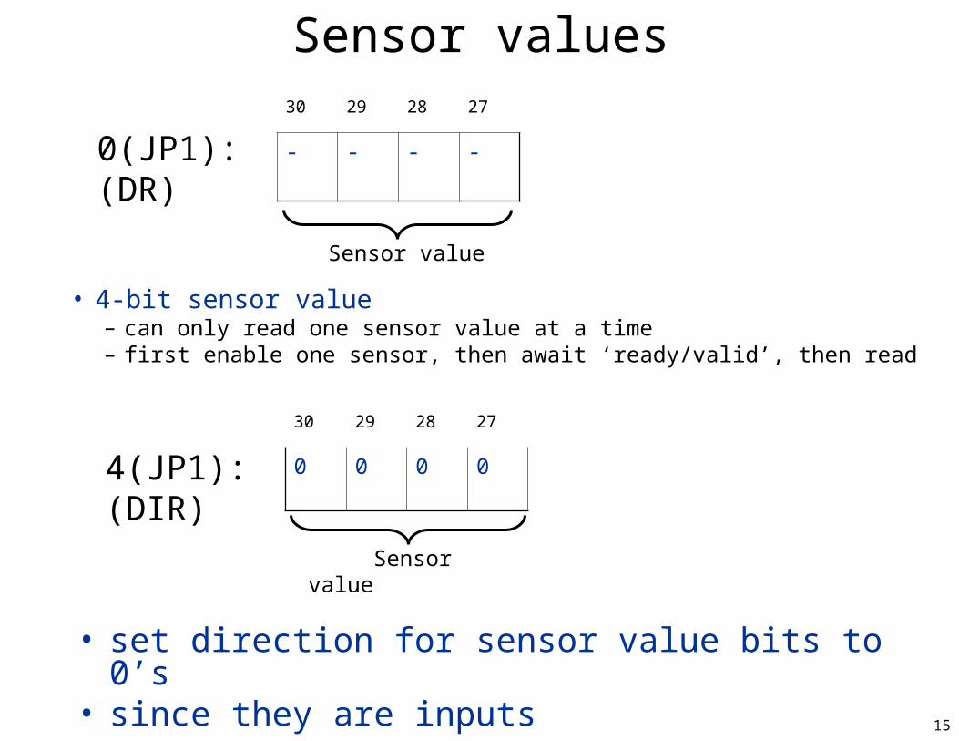
Sensor values30 29 28 27
- - - -
• 4-bit sensor value – can only read one sensor value at a time– first enable one sensor, then await ‘ready/valid’, then read
0(JP1):(DR)
30 29 28 27
0 0 0 04(JP1):(DIR)
• set direction for sensor value bits to 0’s• since they are inputs
Sensor value
Sensor value
16
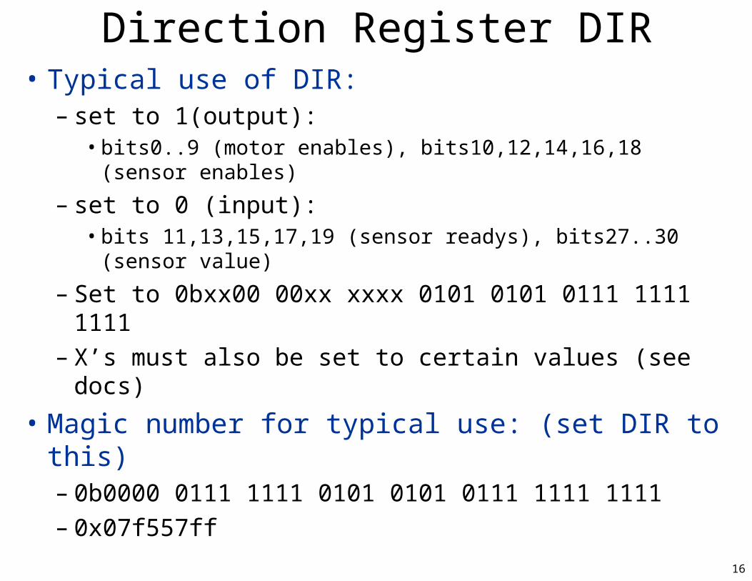
Direction Register DIR• Typical use of DIR:
– set to 1(output): • bits0..9 (motor enables), bits10,12,14,16,18 (sensor enables)
– set to 0 (input): • bits 11,13,15,17,19 (sensor readys), bits27..30 (sensor value)
– Set to 0bxx00 00xx xxxx 0101 0101 0111 1111 1111– X’s must also be set to certain values (see docs)
• Magic number for typical use: (set DIR to this)– 0b0000 0111 1111 0101 0101 0111 1111 1111– 0x07f557ff
17
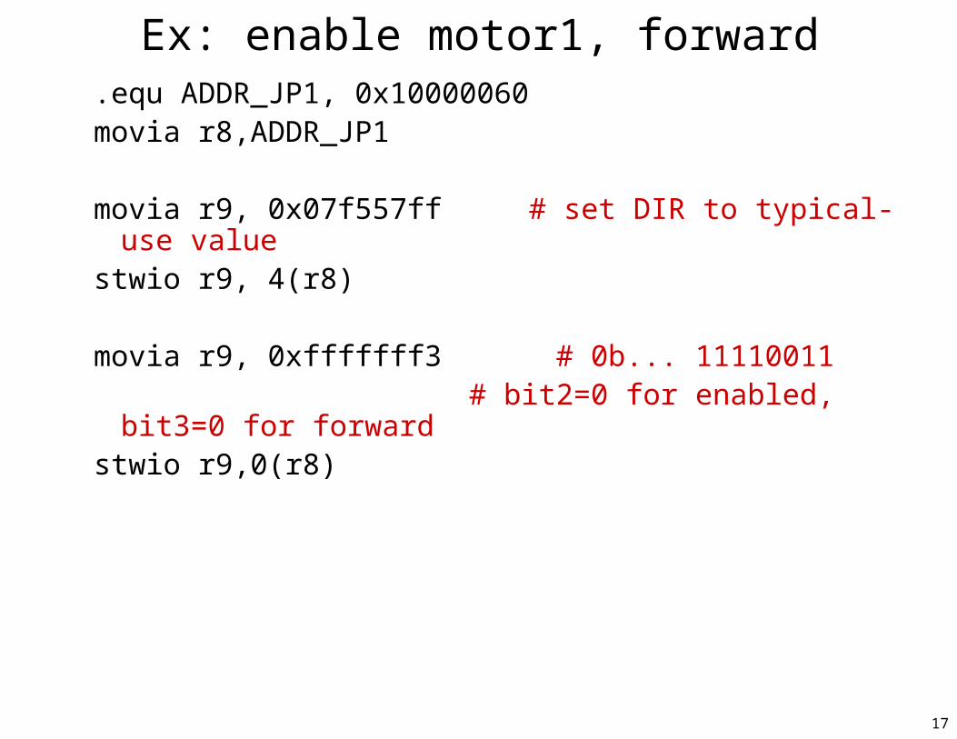
Ex: enable motor1, forward.equ ADDR_JP1, 0x10000060movia r8,ADDR_JP1
movia r9, 0x07f557ff # set DIR to typical-use valuestwio r9, 4(r8)
movia r9, 0xfffffff3 # 0b... 11110011# bit2=0 for enabled, bit3=0 for
forwardstwio r9,0(r8)
18
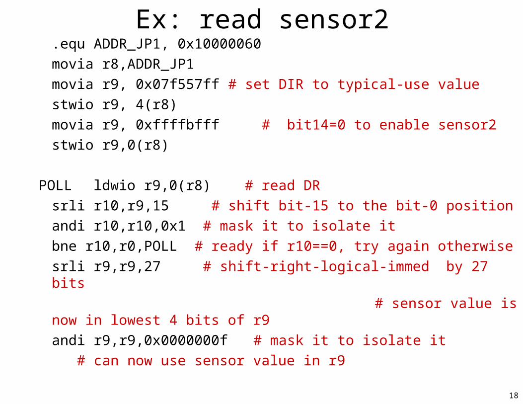
Ex: read sensor2.equ ADDR_JP1, 0x10000060
movia r8,ADDR_JP1
movia r9, 0x07f557ff # set DIR to typical-use value
stwio r9, 4(r8)
movia r9, 0xffffbfff # bit14=0 to enable sensor2
stwio r9,0(r8)
POLL ldwio r9,0(r8) # read DR
srli r10,r9,15 # shift bit-15 to the bit-0 position
andi r10,r10,0x1 # mask it to isolate it
bne r10,r0,POLL # ready if r10==0, try again otherwise
srli r9,r9,27 # shift-right-logical-immed by 27 bits
# sensor value is now in lowest 4 bits of r9
andi r9,r9,0x0000000f # mask it to isolate it
# can now use sensor value in r9
19
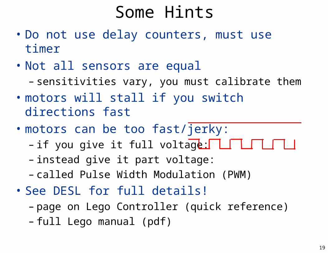
Some Hints• Do not use delay counters, must use timer
• Not all sensors are equal– sensitivities vary, you must calibrate them
• motors will stall if you switch directions fast
• motors can be too fast/jerky:– if you give it full voltage:– instead give it part voltage: – called Pulse Width Modulation (PWM)
• See DESL for full details!– page on Lego Controller (quick reference)– full Lego manual (pdf)