02.11.2005 Satoshi MIHARA, U Zuerich Seminar 1 MEG Experiment at PSI Liquid Xenon Photon Detector...
51
02.11.2005 Satoshi MIHARA, U Zuerich Seminar 1 MEG Experiment at PSI Liquid Xenon Photon Detector Satoshi MIHARA ICEPP, Univ. of Tokyo
-
date post
19-Dec-2015 -
Category
Documents
-
view
216 -
download
1
Transcript of 02.11.2005 Satoshi MIHARA, U Zuerich Seminar 1 MEG Experiment at PSI Liquid Xenon Photon Detector...

02.1
1.20
05
Sat
oshi
MIH
AR
A,
U Z
ueri
ch S
em
inar
1
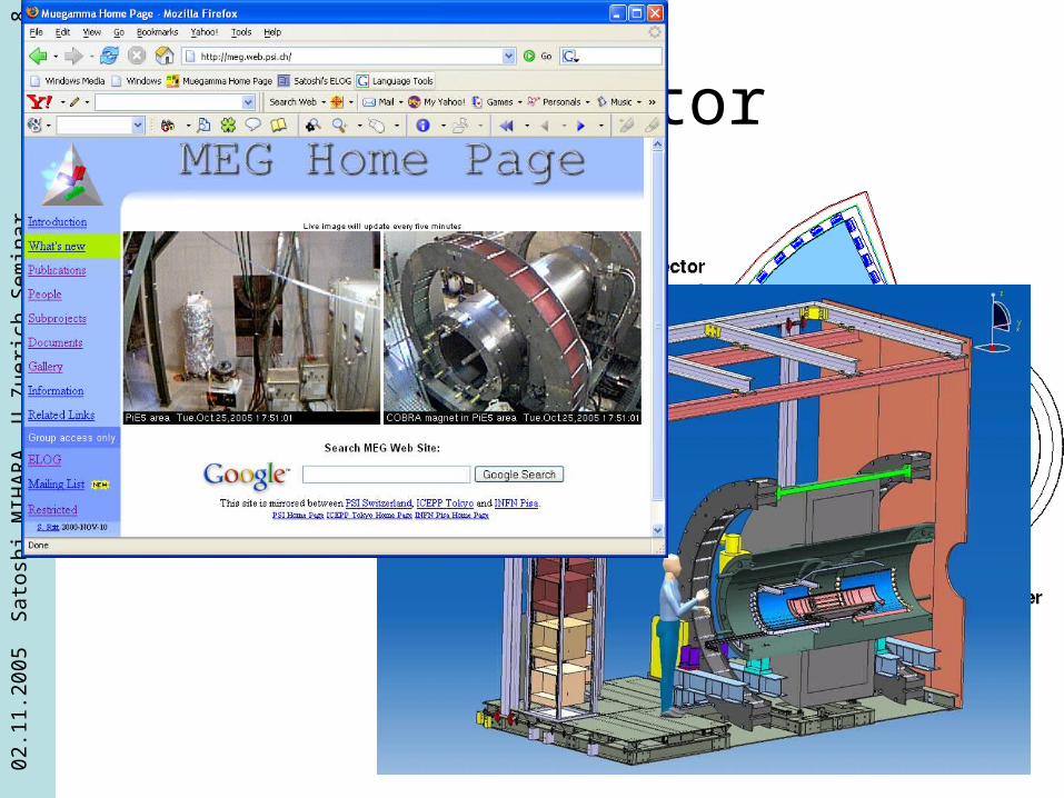
MEG Experiment at PSI
Liquid Xenon Photon Detector
Satoshi MIHARAICEPP, Univ. of Tokyo
02.1
1.20
05
Sat
oshi
MIH
AR
A,
U Z
ueri
ch S
em
inar
2
Contents
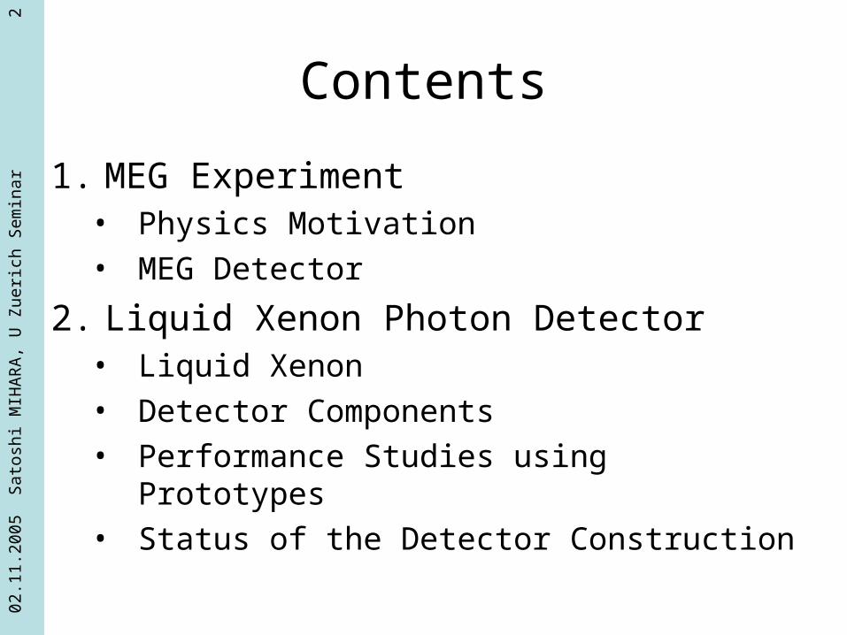
1. MEG Experiment• Physics Motivation• MEG Detector
2. Liquid Xenon Photon Detector• Liquid Xenon• Detector Components• Performance Studies using Prototypes• Status of the Detector Construction

02.1
1.20
05
Sat
oshi
MIH
AR
A,
U Z
ueri
ch S
em
inar
3
μ→eγ
• Lepton Flavor Violation (LFV) is strictly forbidden in SM.
• Neutrino oscillation– LF is not conserved
– Contribute (m∝ /mW)4
• Supersymmetry– Off-diagonal terms in the slepton mass matrix
233
232
231
223
222
221
213
212
211
2~
mmm
mmm
mmm
ml
μ e
W
e
μ e
0~x
e~~
Just below the current limit
Br(μ→eγ) = 1.2 x 10⁻¹¹
(MEGA, PRL 83(1999)83)
02.1
1.20
05
Sat
oshi
MIH
AR
A,
U Z
ueri
ch S
em
inar
4
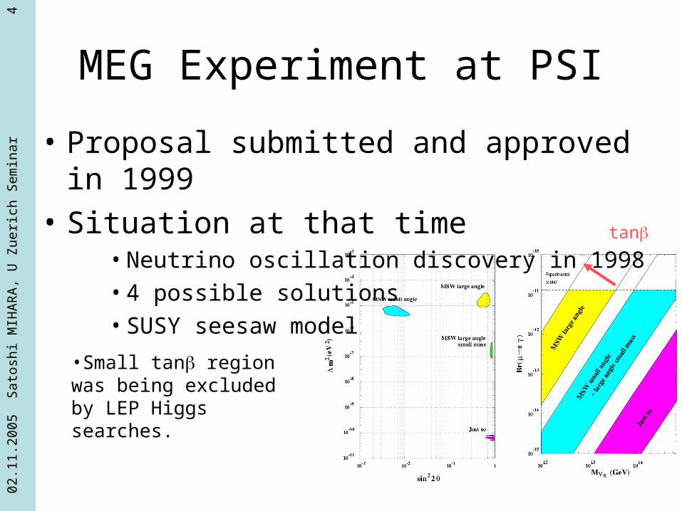
MEG Experiment at PSI
•Small tan region was being excluded by LEP Higgs searches.
tan
• Proposal submitted and approved in 1999
• Situation at that time• Neutrino oscillation discovery in 1998• 4 possible solutions• SUSY seesaw model
02.1
1.20
05
Sat
oshi
MIH
AR
A,
U Z
ueri
ch S
em
inar
5
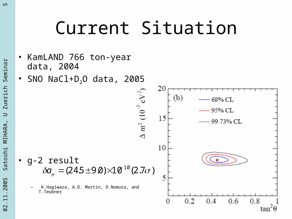
Current Situation
• KamLAND 766 ton-year data, 2004
• SNO NaCl+D2O data, 2005
• g-2 result
– K.Hagiwara, A.D. Martin, D.Nomura, and T.Teubner
)7.2(10)0.95.24( 10 a

02.1
1.20
05
Sat
oshi
MIH
AR
A,
U Z
ueri
ch S
em
inar
6
Signal and Background
• Signal
• E = m/2 = 52.8MeV
• Ee = m/2 = 52.8MeV
• = 180o
• Time coincidence
• Background– Radiative decay
– Accidental overlap
ee
ee
ee????

02.1
1.20
05
Sat
oshi
MIH
AR
A,
U Z
ueri
ch S
em
inar
7
Basic Concept
• Intense DC beam– Reduce pile-up
• Photon Detector– Good resolution
• A few % for Energy• A few mm for position• ~100psec for timing
– Fast response– Uniform
• Positron Detector– Reduce BG Michel positron– Minimum amount of
material
PSI
Liquid Xenon Photon Detector
COBRA Spectrometer
02.1
1.20
05
Sat
oshi
MIH
AR
A,
U Z
ueri
ch S
em
inar
8
MEG Detector

02.1
1.20
05
Sat
oshi
MIH
AR
A,
U Z
ueri
ch S
em
inar
9
COBRA Spectrometer(COnstant Bending Radius)
• Sweep out curling positrons rapidly.• Constant bending radius independent of the
emission angles.

02.1
1.20
05
Sat
oshi
MIH
AR
A,
U Z
ueri
ch S
em
inar
10
COBRA Magnet
• Gradient magnetic field, 1.27 T at z=0• Small magnetic field around the photon
detector.
• 0.197X0 around the center
• Cooling by using two GM-type refrigerators No need of liquid He for operation
CERN Courier 44 number 6 21-22 2004

02.1
1.20
05
Sat
oshi
MIH
AR
A,
U Z
ueri
ch S
em
inar
11
Drift Chamber
• Position resolutions (~300m) for both r and z.
• Vernier pad readout for z measurement• Low material

02.1
1.20
05
Sat
oshi
MIH
AR
A,
U Z
ueri
ch S
em
inar
12
Timing Counter
• Plastic scintillator + Fine-mesh PMTs• SciFi+APD to measure the impact point along the z-direction

02.1
1.20
05
Sat
oshi
MIH
AR
A,
U Z
ueri
ch S
em
inar
13
Xenon Detector

02.1
1.20
05
Sat
oshi
MIH
AR
A,
U Z
ueri
ch S
em
inar
14
Liquid Xenon Detector
• Why liquid xenon?
• How the detector works?
• Components
• Performance Study using prototypes
• Status of the detector construction
02.1
1.20
05
Sat
oshi
MIH
AR
A,
U Z
ueri
ch S
em
inar
15
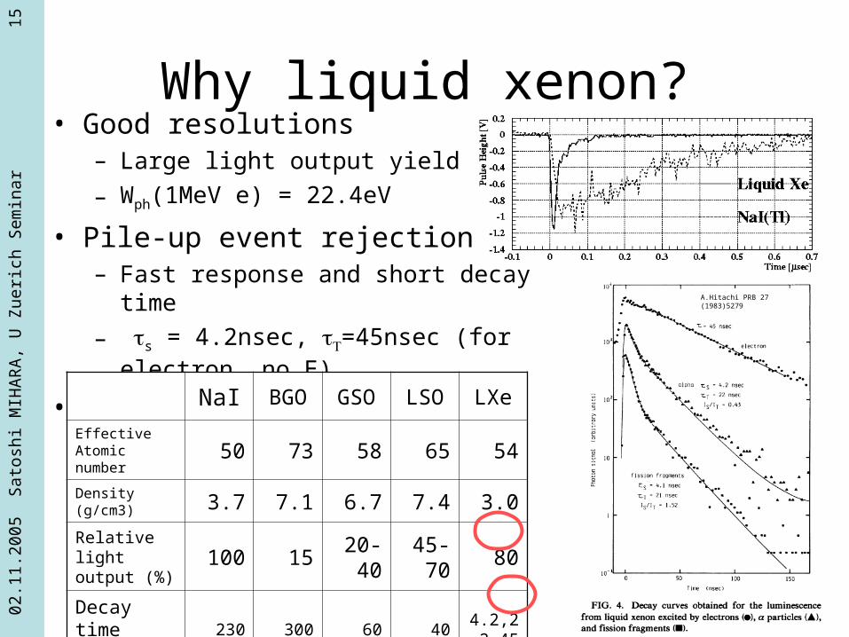
Why liquid xenon?• Good resolutions
– Large light output yield
– Wph(1MeV e) = 22.4eV
• Pile-up event rejection– Fast response and short decay time
– s = 4.2nsec, =45nsec (for electron, no E)
• Uniform
NaI BGO GSO LSO LXe
Effective Atomic number 50 73 58 65 54
Density (g/cm3) 3.7 7.1 6.7 7.4 3.0
Relative light output (%) 100 15
20-40
45-70
80
Decay time (nsec)
230 300 60 404.2,22,
45
A.Hitachi PRB 27 (1983)5279
02.1
1.20
05
Sat
oshi
MIH
AR
A,
U Z
ueri
ch S
em
inar
16
Liquid Xenon and Sci light
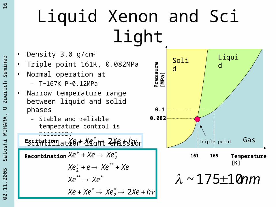
• Density 3.0 g/cm3
• Triple point 161K, 0.082MPa
• Normal operation at– T~167K P~0.12MPa
• Narrow temperature range between liquid and solid phases
– Stable and reliable temperature control is necessary
• Scintillation light emission mechanism
Solid Liquid
GasTriple point
Temperature [K]P
ress
ure
[M
Pa]
161
0.082
0.1
165
hXeXeXe 2*
hXeXeXeXe
XeXe
XeXeeXe
XeXeXe
2*2
*
***
**2
2
Excitation
Recombination
nm10175~

02.1
1.20
05
Sat
oshi
MIH
AR
A,
U Z
ueri
ch S
em
inar
17
MEG Xenon Detector
• Active volume ~800l is surrounded PMTs on all faces
• ~850PMTs in the liquid• No segmentation• Energy
– All PMT outputs
• Position– PMTs on the inner face
• Timing– Averaging of signal arrival time of
selected PMTs

02.1
1.20
05
Sat
oshi
MIH
AR
A,
U Z
ueri
ch S
em
inar
18
Reconstruction of the event depth
• Using event broadness on the inner face
• Necessary to achieve good timing resolution
3 cm
Liq. Xe
Liq. Xe
14 cm
(a)
(b)
05 10 15
2025
3035
0
10
20
30
40
50
0
2000
4000
6000
8000
10000
05
1015 20 25
3035
0
10
20
30
40
50
0
200
400
600
800
1000
1200
1400
1600
1800
52.8 MeV
52.8 MeV

02.1
1.20
05
Sat
oshi
MIH
AR
A,
U Z
ueri
ch S
em
inar
19
Detector Components
• Photomultiplier– Operational in liquid xenon, Compact– UV light sensitive
• Refrigerator– Stable temperature control– Sufficient power to liquefy xenon– Low noise, maintenance free
• Xenon Purifier– Purification during detector operation

02.1
1.20
05
Sat
oshi
MIH
AR
A,
U Z
ueri
ch S
em
inar
20
Photomultiplier R&D• Photocathode
– Bialkali :K-Cs-Sb, Rb-Cs-Sb• Rb-Cs-Sb has less steep increase of sheet resistance
at low temperature• K-Cs-Sb has better sensitivity than Rb-Cs-Sb
– Multialkali :+Na• Sheet resistance of Multialkali dose not change so
much.• Difficult to make the photocathod, noisy
• Dynode Structure– Compact– Possible to be used in magnetic field up to 100G
• Metal channel Uniformity is not excellent
Ichige et al. NIM A327(1993)144

02.1
1.20
05
Sat
oshi
MIH
AR
A,
U Z
ueri
ch S
em
inar
21
1st generation R6041Q 2nd generation R9288TB 3rd generation R9869
228 in the LP (2003 CEX and TERAS)
127 in the LP (2004 CEX)
111 In the LP (2004 CEX) Not used yet in the LP
Rb-Sc-Sb
Mn layer to keep surface resistance at low temp.
K-Sc-Sb
Al strip to fit with the dynode pattern to keep surface resistance at low temp.
K-Sc-Sb
Al strip density is doubled.
4% loss of the effective area.
1st compact version
QE~4-6%
Under high rate background,
PMT output reduced by 10
-20% with a time constant of
order of 10min.
Higher QE ~12-14%
Good performance in high rate BG
Still slight reduction of output in very high BG
Higher QE~12-14%
Much better performance in very high BG
PMT Development Summary

02.1
1.20
05
Sat
oshi
MIH
AR
A,
U Z
ueri
ch S
em
inar
22
PMT Base Circuit
Reference PMT = no Zener
PMT with Zener
• Necessary to reduce heat load from the circuit– Heat load in the cryostat ↔ Refrigerator cooling
power ~150W– Reduce base current
• 800V 55microA 44mW/PMT
• 40-50W heat load from 850PMTs
– Zener diodes at last 2 stages for high rate background
• Zener diode is very noisy at low temperature filtering on the base
02.1
1.20
05
Sat
oshi
MIH
AR
A,
U Z
ueri
ch S
em
inar
23
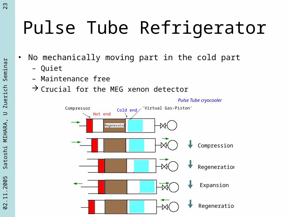
Pulse Tube Refrigerator
• No mechanically moving part in the cold part– Quiet
– Maintenance free Crucial for the MEG xenon detector
Compressor
Regenerator
Hot endCold end 'Virtual Gas-Piston'
Compression
Regeneration
Expansion
Regeneration
Regenerator
Pulse Tube cryocooler

02.1
1.20
05
Sat
oshi
MIH
AR
A,
U Z
ueri
ch S
em
inar
24
Refrigerator R&D
• MEG 1st spin-off
• Technology transferred to a manufacturer, Iwatani Co. Ltd
• Performance obtained at Iwatani– 189 W @165K
– 6.7 kW compressor
– 4 Hz operation
Cool i ng power (PC150)
0
50
100
150
200
50 100 150 200
Col d end temperature(K)
Cooling power (W)
Qi wa(W)Qpsi (W)

02.1
1.20
05
Sat
oshi
MIH
AR
A,
U Z
ueri
ch S
em
inar
25
Xenon Purifier
• Attenuation of Sci light– Scintillation light emission from an excited molecule
• Xe+Xe*Xe2*2Xe + h
– Attenuation• Rayleigh scattering Ray~30-45cm
• Absorption by impurity

02.1
1.20
05
Sat
oshi
MIH
AR
A,
U Z
ueri
ch S
em
inar
26
Possible Contaminants
• Remaining Gas Analysis (RGA) for investigating what causes short absorption length.
• Remaining gas in the chamber was sampled to the analyzing section.
• Vacuum level– LP Chamber 2.0x10⁻²Pa
– Analyzing section 2.0x10⁻³Pa
HeH2O CO/N2
O2
CO2Xe
02.1
1.20
05
Sat
oshi
MIH
AR
A,
U Z
ueri
ch S
em
inar
27
Water Contamination
• Usually water can be removed by heating the cryostat during evacuation.
• MEG liq. Xenon detector cannot be heated because of the PMTs inside.
• Water molecule is usually trapped on cold surface in the cryostat. However when the cryostat is filled with fluid, water molecules seem to dissolve in the fluid.
• Circulation/Purification after filling with fluid.
02.1
1.20
05
Sat
oshi
MIH
AR
A,
U Z
ueri
ch S
em
inar
28
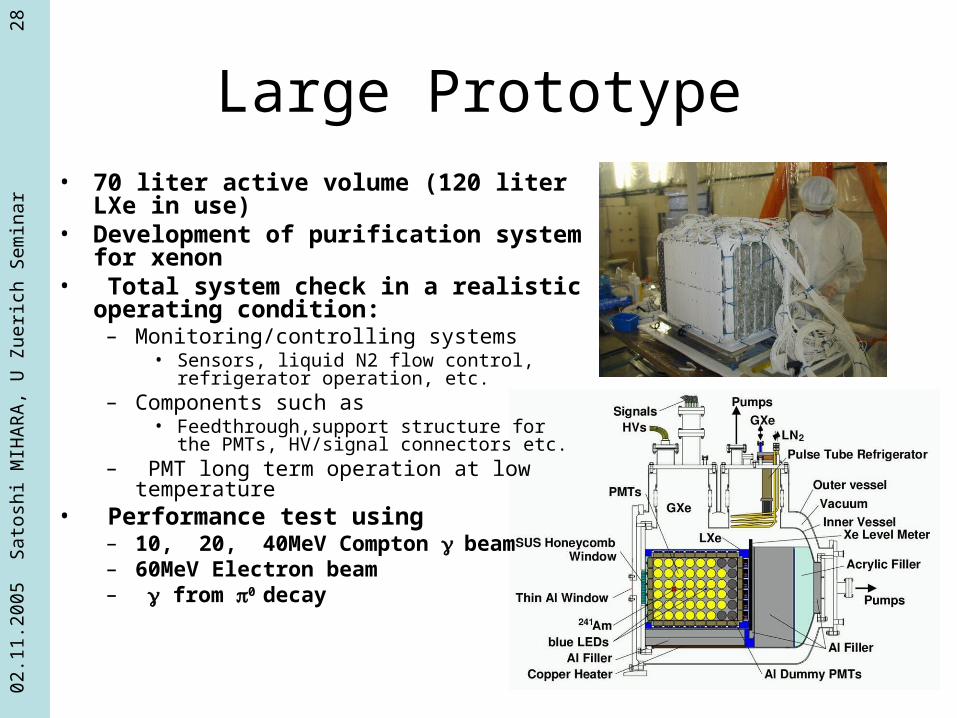
Large Prototype• 70 liter active volume (120 liter LXe in use)• Development of purification system for
xenon• Total system check in a realistic operating
condition:– Monitoring/controlling systems
• Sensors, liquid N2 flow control, refrigerator operation, etc.
– Components such as• Feedthrough,support structure for the PMTs,
HV/signal connectors etc.– PMT long term operation at low temperature
• Performance test using– 10, 20, 40MeV Compton beam– 60MeV Electron beam– from 0 decay
02.1
1.20
05
Sat
oshi
MIH
AR
A,
U Z
ueri
ch S
em
inar
29
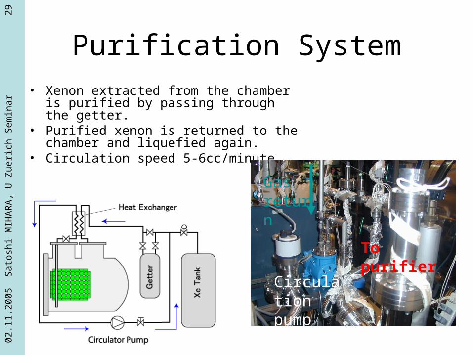
Purification System• Xenon extracted from the chamber is
purified by passing through the getter.• Purified xenon is returned to the chamber
and liquefied again.• Circulation speed 5-6cc/minute
Gas return
To purifier
Circulation pump

02.1
1.20
05
Sat
oshi
MIH
AR
A,
U Z
ueri
ch S
em
inar
30
Heated Metal Getter Purifier• Metal getter technology based on zirconium
metals form irreversible chemical bonds to remove all oxide, carbide and nitride impurities
• Getter Material (GM) such as Zr– GM + O2 GMO– GM + N2 GMN– GM + CO2 CO + GMO GMC + GMO– GM + CO GMC + GMO– GM + H2O H + GMO GMO + H (bulk)– GM + H2 GM + H (bulk)– GM + Hydrocarbons, CxHx, etc. GMC + H (bulk)– GM + He, Ne, Ar, Kr, Xe (inert gases) No reaction
• These chemical reactions occur on the surface of the metal, and the reaction products then diffuse into the bulk structure.
• Longer life time than catalyst media• Need temperature control of the metal
Heat allows bulkdiffusion of impurities

02.1
1.20
05
Sat
oshi
MIH
AR
A,
U Z
ueri
ch S
em
inar
31
Purification Performance• Xenon Detector Large
Prototype• 3 sets of Cosmic-ray trigger
counters• 241Am alpha sources on the
PMT holder• Stable detector operation for
more than 1200 hours
Cosmic-ray events events

02.1
1.20
05
Sat
oshi
MIH
AR
A,
U Z
ueri
ch S
em
inar
32
Absorption Length• Fit the data with a function :
A exp(-x/ abs)• abs >100cm (95% C.L)
from comparison with MC.• CR data indicate that abs >
100cm has been achieved after purification.

02.1
1.20
05
Sat
oshi
MIH
AR
A,
U Z
ueri
ch S
em
inar
33
Upgrade of the system
• Purification in Gas phase– Evaporate and liquefy
• Slow• Cooling power consumption
• We know that water is the main impurity to be removed.– Purification system
dedicated to remove water– Not in gas phase but in
liquid phase

02.1
1.20
05
Sat
oshi
MIH
AR
A,
U Z
ueri
ch S
em
inar
34
Liquid-phase Purification System
• Xenon circulation in liquid phase.• Impurity (water) is removed by a
purifier cartridge filled with molecular sieves.
• 100 l/hour circulation.

02.1
1.20
05
Sat
oshi
MIH
AR
A,
U Z
ueri
ch S
em
inar
35
Temperature Sensor
PMT’s
Purifier Cartridge
Molecular sieves, 13X 25g water
Freq. InverterOMRON
PT
Liquid-phase Purifier Prototype

02.1
1.20
05
Sat
oshi
MIH
AR
A,
U Z
ueri
ch S
em
inar
36
Liquid-phase Purification Performance
In ~10 hours, λabs ~ 5m
02.1
1.20
05
Sat
oshi
MIH
AR
A,
U Z
ueri
ch S
em
inar
37
Performance Studies
• Small Prototype– Test of the detector principle
• Large Prototype– Inverse-Compton beam– 0 produced via charge exchange
process -pn

02.1
1.20
05
Sat
oshi
MIH
AR
A,
U Z
ueri
ch S
em
inar
38
TERAS Beam
• Electron beam (TERAS, Tsukuba in Japan)– Energy: 764MeV– Energy spread: 0.48%(sigma)– Divergence: <0.1mrad(sigma)– Beam size: 1.6mm(sigma)
• Laser photon– Energy: 1.17e-6x4 eV (for 40MeV)– Energy spread: 2x10⁻⁵ (FWHM)– Divergence: unknown– Beam size: unknown
Compton Spectrum
•(E-Ec/2)2+(Ec/2)2
Collimator size
10MeV
20MeV40MeV

02.1
1.20
05
Sat
oshi
MIH
AR
A,
U Z
ueri
ch S
em
inar
39
Energy Spectrum Fitting
• Principle…
E Npe
Convolution of
Compton Spectrum
Response Function
Suppose Compton Spectrum around the edge
(E-Ec/2)2+Ec2/4Detector Response Function
Gaussian with Exponential tailf(x) = N*exp{t/2(t/2-(x-x0)}, x<x0+t N*exp{-1/2((x-x0)/)2}, x>x0+t
ConvolutionIntegration +/- 5
E~1.9%
02.1
1.20
05
Sat
oshi
MIH
AR
A,
U Z
ueri
ch S
em
inar
40
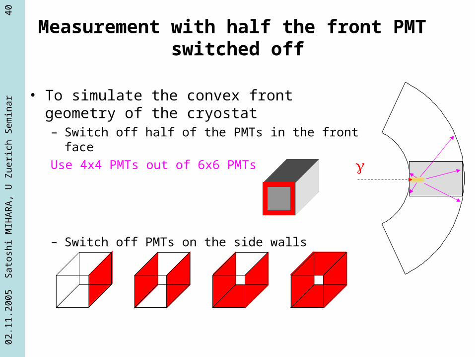
Measurement with half the front PMT switched off
• To simulate the convex front geometry of the cryostat – Switch off half of the PMTs in the front face
Use 4x4 PMTs out of 6x6 PMTs
– Switch off PMTs on the side walls

02.1
1.20
05
Sat
oshi
MIH
AR
A,
U Z
ueri
ch S
em
inar
44
CEX beam test• Charge Exchange elementary process• -p0n
– 0(28MeV/c) – 54.9 MeV < E() < 82.9 MeV
• Requiring
FWHM = 1.3 MeV
• Requiring > 175o
FWHM = 0.3 MeV
170o
175o
0
54.9MeV 82.9MeV
1.3MeV for >170o
0.3MeV for >175o

02.1
1.20
05
Sat
oshi
MIH
AR
A,
U Z
ueri
ch S
em
inar
45
Beam Test Setup
H2 target+degrader
beam
LPNaI
LYSO
Eff ~14%
S1Eff(S1xLP)~88%

02.1
1.20
05
Sat
oshi
MIH
AR
A,
U Z
ueri
ch S
em
inar
46
Energy Resolutions
83 MeV to Xe83 MeV to Xe
55 MeV to Xe55 MeV to Xe
Exe
non[
n ph]
= 1.23 ±0.09 %FWHM=4.8 %
55 MeV
σ = 1.00±0.08 % FWHM=5.2%
83 MeV
CEX 2004

02.1
1.20
05
Sat
oshi
MIH
AR
A,
U Z
ueri
ch S
em
inar
47
Right is a nice function of gamma energy
PSI 2003TERAS 2003alpha
Energy Resolution vs Energy

02.1
1.20
05
Sat
oshi
MIH
AR
A,
U Z
ueri
ch S
em
inar
48
Position Reconstruction
• Localized Weight Method
• Projection to x and y directions.
• Peak point and distribution spread
•Position reconstruction using the selected PMT

02.1
1.20
05
Sat
oshi
MIH
AR
A,
U Z
ueri
ch S
em
inar
49
Examples of Reconstruction
(40 MeV gamma beam w/ 1 mm collimator)
02.1
1.20
05
Sat
oshi
MIH
AR
A,
U Z
ueri
ch S
em
inar
50
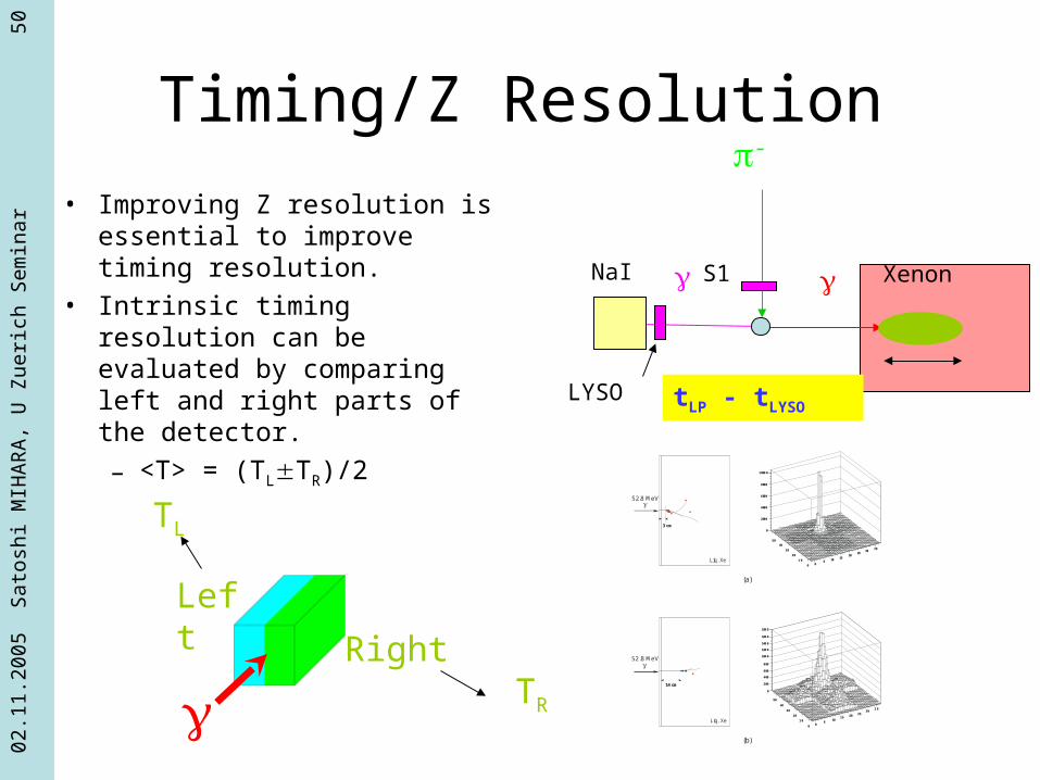
Timing/Z Resolution
• Improving Z resolution is essential to improve timing resolution.
• Intrinsic timing resolution can be evaluated by comparing left and right parts of the detector.
– <T> = (TLTR)/2
XenonNaI S1
LYSO tLP - tLYSO
-
3 cm
Liq. Xe
Liq. Xe
14 cm
(a)
(b)
05 10 15
2025
3035
0
10
20
30
4050
0
2000
4000
6000
8000
10000
05
1015 20 25
3035
0
10
20
30
40
50
0
200
400
600
800
1000
1200
1400
1600
1800
52.8 MeV
52.8 MeV
Left
Right
TL
TR

02.1
1.20
05
Sat
oshi
MIH
AR
A,
U Z
ueri
ch S
em
inar
51
Absolute timing, Xe-LYSO analysis55 M
eV
high gainnormal gain
110 psec 103 psec
LYSO Beam L-R depth reso.
110 64 61 = 65 = 56 33 psec
103 64 61 = 53 = 43 31 psec
No
rma
l g
ain
Hig
h
ga
in
A few cm in Z

02.1
1.20
05
Sat
oshi
MIH
AR
A,
U Z
ueri
ch S
em
inar
52
Status of Xenon Detector Construction
• PMT– 850 PMTs being tested in PSI
and Pisa
• Cryostat– Under construction– Delivery to PSI early in 2006
• Gas system– Getting ready in E5 area in PSI

02.1
1.20
05
Sat
oshi
MIH
AR
A,
U Z
ueri
ch S
em
inar
53
Summary
• MEG at PSI– Search for μ→eγ with better sensitivity than
previous experiments• Xenon detector• COBRA spectrometer• PSI beam
– Detector preparation will finish in several months
– DAQ in 2006

02.1
1.20
05
Sat
oshi
MIH
AR
A,
U Z
ueri
ch S
em
inar
54
Further Information
• Beam• Drift Chamber system• Timing Counter• Electronics• Software• Waveform analysis• Etc.
Please visit http://meg.psi.ch


![[Satoshi Kamiya] Ancient Dragon](https://static.fdocument.pub/doc/165x107/5449d023af79598c188b4622/satoshi-kamiya-ancient-dragon.jpg)