雷サージ試験サービス Surge Test Service Materials is pleased to offer customers surge...
52
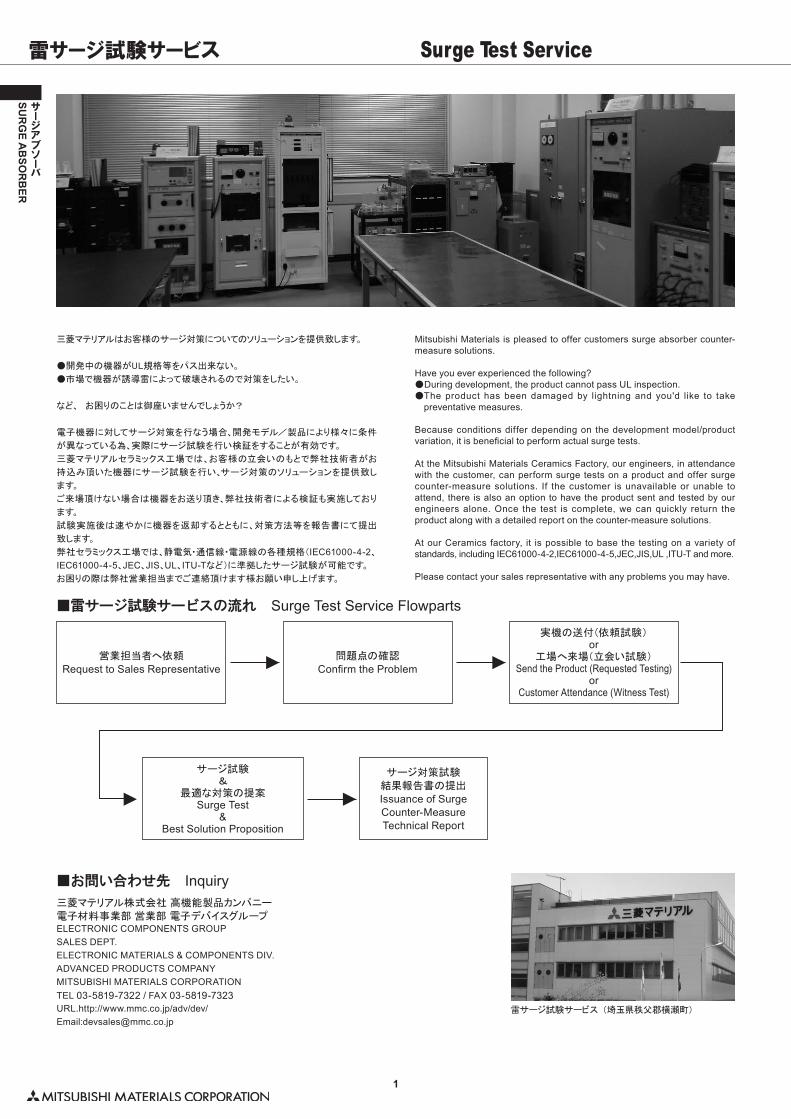
1 SURGE ABSORBER サージアブソーバ雷サージ試験サービス (埼玉県秩父郡横瀬町) 雷サージ試験サービス Surge Test Service 三菱マテリアルはお客様のサージ対策についてのソリューションを提供致します。 ●開発中の機器がUL規格等をパス出来ない。 ●市場で機器が誘導雷によって破壊されるので対策をしたい。 など、 お困りのことは御座いませんでしょうか? 電子機器に対してサージ対策を行なう場合、開発モデル/製品により様々に条件 が異なっている為、実際にサージ試験を行い検証をすることが有効です。 三菱マテリアルセラミックス工場では、お客様の立会いのもとで弊社技術者がお 持込み頂いた機器にサージ試験を行い、サージ対策のソリューションを提供致し ます。 ご来場頂けない場合は機器をお送り頂き、弊社技術者による検証も実施しており ます。 試験実施後は速やかに機器を返却するとともに、対策方法等を報告書にて提出 致します。 弊社セラミックス工場では、静電気・通信線・電源線の各種規格(IEC61000-4-2、 IEC61000-4-5、JEC、JIS、 UL、 ITU-Tなど)に準拠したサージ試験が可能です。 お困りの際は弊社営業担当までご連絡頂けます様お願い申し上げます。 Mitsubishi Materials is pleased to offer customers surge absorber counter- measure solutions. Have you ever experienced the following? ●During development, the product cannot pass UL inspection. ●The product has been damaged by lightning and you'd like to take preventative measures. Because conditions differ depending on the development model/product variation, it is beneficial to perform actual surge tests. At the Mitsubishi Materials Ceramics Factory, our engineers, in attendance with the customer, can perform surge tests on a product and offer surge counter-measure solutions. If the customer is unavailable or unable to attend, there is also an option to have the product sent and tested by our engineers alone. Once the test is complete, we can quickly return the product along with a detailed report on the counter-measure solutions. At our Ceramics factory, it is possible to base the testing on a variety of standards, including IEC61000-4-2,IEC61000-4-5,JEC,JIS,UL ,ITU-T and more. Please contact your sales representative with any problems you may have. ■雷サージ試験サービスの流れ Surge Test Service Flowparts 営業担当者へ依頼 Request to Sales Representative 問題点の確認 Confirm the Problem 実機の送付(依頼試験) or 工場へ来場(立会い試験) Send the Product (Requested Testing) or Customer Attendance (Witness Test) サージ試験 & 最適な対策の提案 Surge Test & Best Solution Proposition サージ対策試験 結果報告書の提出 Issuance of Surge Counter-Measure Technical Report ■お問い合わせ先 Inquiry 三菱マテリアル株式会社 高機能製品カンパニー 電子材料事業部 営業部 電子デバイスグループ ELECTRONIC COMPONENTS GROUP SALES DEPT. ELECTRONIC MATERIALS & COMPONENTS DIV. ADVANCED PRODUCTS COMPANY MITSUBISHI MATERIALS CORPORATION TEL 03-5819-7322 / FAX 03-5819-7323 URL.http://www.mmc.co.jp/adv/dev/ Email:[email protected]
Transcript of 雷サージ試験サービス Surge Test Service Materials is pleased to offer customers surge...
1
SUR
GE A
BSO
RB
ER
サージアブソーバ
雷サージ試験サービス (埼玉県秩父郡横瀬町)
雷サージ試験サービス Surge Test Service
三菱マテリアルはお客様のサージ対策についてのソリューションを提供致します。
●�開発中の機器がUL規格等をパス出来ない。
●�市場で機器が誘導雷によって破壊されるので対策をしたい。
など、 お困りのことは御座いませんでしょうか?
電子機器に対してサージ対策を行なう場合、開発モデル/製品により様々に条件
が異なっている為、実際にサージ試験を行い検証をすることが有効です。
三菱マテリアルセラミックス工場では、お客様の立会いのもとで弊社技術者がお
持込み頂いた機器にサージ試験を行い、サージ対策のソリューションを提供致し
ます。
ご来場頂けない場合は機器をお送り頂き、弊社技術者による検証も実施しており
ます。
試験実施後は速やかに機器を返却するとともに、対策方法等を報告書にて提出
致します。
弊社セラミックス工場では、静電気・通信線・電源線の各種規格(IEC61000-4-2、IEC61000-4-5、JEC、JIS、UL、ITU-Tなど)に準拠したサージ試験が可能です。
お困りの際は弊社営業担当までご連絡頂けます様お願い申し上げます。
Mitsubishi Materials is pleased to offer customers surge absorber counter-measure solutions.
Have you ever experienced the following?●�During development, the product cannot pass UL inspection.●�The product has been damaged by lightning and you'd like to take
preventative measures.
Because conditions differ depending on the development model/product variation, it is beneficial to perform actual surge tests.
At the Mitsubishi Materials Ceramics Factory, our engineers, in attendance with the customer, can perform surge tests on a product and offer surge counter-measure solutions. If the customer is unavailable or unable to attend, there is also an option to have the product sent and tested by our engineers alone. Once the test is complete, we can quickly return the product along with a detailed report on the counter-measure solutions.
At our Ceramics factory, it is possible to base the testing on a variety of standards, including IEC61000-4-2,IEC61000-4-5,JEC,JIS,UL ,ITU-T and more.
Please contact your sales representative with any problems you may have.
■雷サージ試験サービスの流れ Surge Test Service Flowparts
営業担当者へ依頼
Request to Sales Representative問題点の確認
Confirm the Problem
実機の送付(依頼試験)or
工場へ来場(立会い試験)Send the Product (Requested Testing)
orCustomer Attendance (Witness Test)
サージ試験&
最適な対策の提案Surge Test
&Best Solution Proposition
サージ対策試験
結果報告書の提出
Issuance of Surge Counter-MeasureTechnical Report
■お問い合わせ先 Inquiry三菱マテリアル株式会社�高機能製品カンパニー
電子材料事業部�営業部�電子デバイスグループELECTRONIC COMPONENTS GROUPSALES DEPT.ELECTRONIC MATERIALS & COMPONENTS DIV.ADVANCED PRODUCTS COMPANYMITSUBISHI MATERIALS CORPORATIONTEL 03-5819-7322 / FAX 03-5819-7323URL.http://www.mmc.co.jp/adv/dev/Email:[email protected]
2
SUR
GE A
BSO
RB
ER
サージアブソーバ
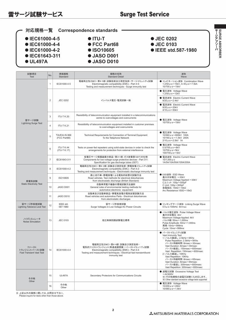
対応規格一覧 Correspondence standards
● �IEC61000-4-5● �IEC61000-4-4● �IEC61000-4-2● �IEC61643-311● �UL497A
● �ITU-T● �FCC Part68● �ISO10605● �JASO D001● �JASO D010
● �JEC 0202● �JEC 0103● �IEEE std.587-1980
雷サージ試験サービス Surge Test Service
試験項目Test No. 準拠規格
Standard規格の名称
Standard Detail波形Wave
雷サージ試験
Lightning Surge Test
1 IEC61000-4-5電磁両立性(EMC)−第4-5部:試験技術及び測定技術−サージイミュニティ試験
Electromagnetic compatibility (EMC) - Part 4-5: Testing and measurement techniques - Surge immunity test
●�コンビネーション波形 Combination Wave 1.2/50μs〜15kV、8/20μs〜7.5kA 10/700μs〜15kV
2 JEC 0202 インパルス電圧・電流試験一般
●�電圧波形 Voltage Wave 1.2/50μs〜12kV
●�電流波形 Electric Current Wave 8/20μs〜2.4kV
●�電流波形 Electric Current Wave 8/20μs〜20kV 4/10μs〜50kV
3 ITU-T K.20 Resistibility of telecommunication equipment installed in a telecommunications centre to overvoltages and overcurrents
●�電圧波形 Voltage Wave 10/700μs〜15kV
4 ITU-T K.21 Resistibility of telecommunication equipment installed in customer premises to overvoltages and overcurrents
5 TIA/EIA-IS-968(FCC Part68)
Technical Requirements for Connection of Terminal EquipmentTo the Telephone Network
●�電圧波形 Voltage Wave 10/560μs〜800kV��100A 10/160μs-〜1.5kV��200A 2/10μs〜2.5kV��1A
6 ITU-T K.44(ITU-T K.17)
Tests on power-fed repeaters using solid-state devices in order to check the arrangements for protection from external interference
●�電圧波形 Voltage Wave 0.5/700μs〜6kV 10/700μs〜5kV 100/700μs〜5kV
7 IEC61643-311低電圧サージ保護装置の部品−第311部:ガス放電管(GDT)の仕様Components for low-voltage surge protective devices - Part 311:
Specification for gas discharge tubes (GDT)
●�電流波形 Electric Current Wave 10/1,000μs 1A/5A/10A/50A/100A/200A
静電気試験Static Electricity Test
8 IEC61000-4-2電磁両立性(EMC)−第4-2部:試験及び測定技術−静電放電イミュニティ試験�
Electromagnetic compatibility (EMC) - Part 4-2: Testing and measurement techniques - Electrostatic discharge immunity test
●�ESD波形 ESD Wave� 最大印加電圧:〜30kV Maximum Voltage Applied:〜30kV� Cユニット:100p〜500pF� C Unit :100p〜500pF� 放電抵抗:150Ω〜10kΩ� Arc Resistance:150Ω〜10kΩ
9 ISO10605路上走行車−静電放電による電気的妨害の試験方法
Road vehicles. Test methods for electrical disturbances from electrostatic discharge (British Standard)
10 JASO D001自動車用電子機器の環境試験方法通則
General rules of environmental testing methods for automotive electronic equipment
11 JASO D010自動車及び自動車部品−静電気放電の電気妨害試験方法
Road vehicles and automotive Parts - Electrical disturbances from electrostatic discharges
雷サージ許容度試験Lightning Tolerance Level Test 12 IEEE std.
587-1980雷サージ許容度試験
Surge Voltages in Low-Voltage AC Power Circuits●�リンキングサージ波形 Linking Surge Wave 0.5μs-100kHz��6kVmax
ノイズシミュレータNoise Simulation 13 JEC 0103 低圧制御回路試験電圧標準
●�パルス電圧波形 Pulse Voltage Wave� 最大印加電圧:4kV Maximum Voltage Applied:4kV� パルス幅:50ns〜1,000ns Pulse Amplitude:50ns〜1,000ns� 周期:10ms〜999ms Cycle:10ms〜999ms
ファーストトランジェントバースト試験Fast Transient Vast Test
14 IEC61000-4-4
電磁両立性(EMC)−第4-4部:試験及び測定技術−電気的ファストトランジェント(高速過渡現象)/バーストイミュニティ試験�
Electromagnetic compatibility (EMC) - Part 4-4: Testing and measurement techniques - Electrical fast transient/burst
immunity test
●�バーストイミュニティ試験 Vast Immunity Test � 1)�パルス繰返し:2.5kHz〜5KHz Pulse Repetition:2.5kHz〜5KHz� � バースト持続時間:8msec〜30msec Vast Duration:8msec〜30msec� � バースト繰返し:150msec〜600msec Vast Repetition:150msec〜600msec� 2)�パルス繰返し:10KHz Vast Repetition:10KHz� � バースト持続時間:8msec〜65msec Vast Duration:8msec〜65msec� � バースト繰返し:300msec〜600msec Vast Repetition:300msec〜600msec
その他Other
15 UL497A Secondary Protectors for Communications Circuits
●�過電圧試験 Excessive Voltage Test 〜AC600V ※)その他規格の過電圧試験にも対応します。 ※)Other standard excessive voltage tests supported
16 その他Other
●�電圧波形 Voltage Wave 10/200μs〜20kV 10/560μs〜1.6kV
※�上記以外の規格に関しては、お問合せ下さい。 Please inquire for tests other than those above.
3
SUR
GE A
BSO
RB
ER
サージアブソーバ
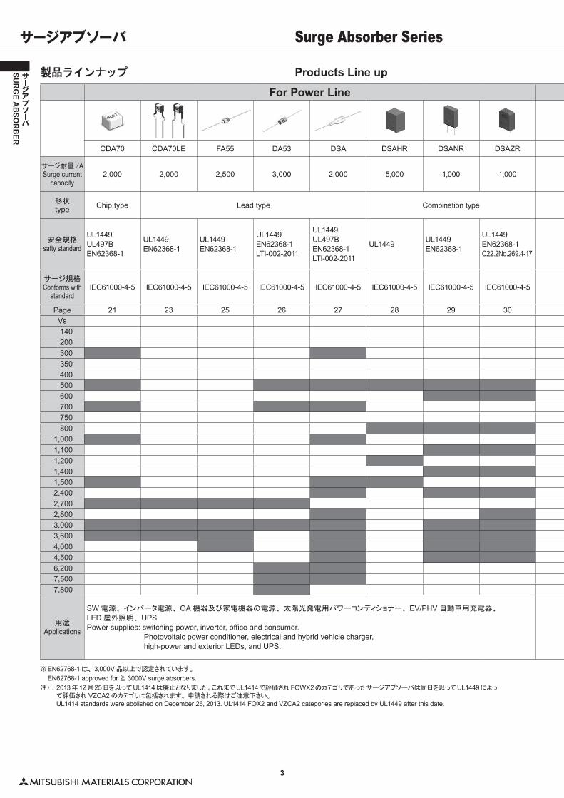
Products Line up製品ラインナップ
サージアブソーバ
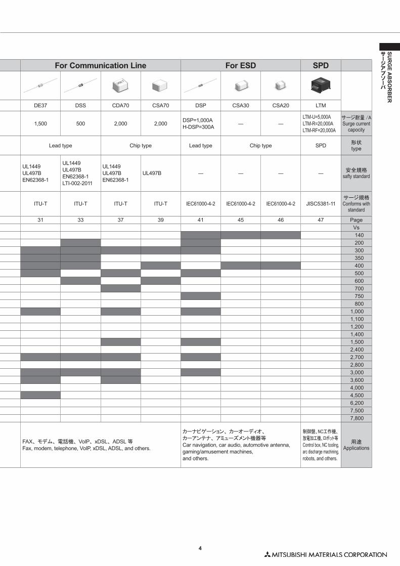
For Power Line For Communication Line For ESD SPD
CDA70 CDA70LE FA55 DA53 DSA DSAHR DSANR DSAZR DE37 DSS CDA70 CSA70 DSP CSA30 CSA20 LTM
サージ耐量 /ASurge current
capocity2,000 2,000 2,500 3,000 2,000 5,000 1,000 1,000 1,500 500 2,000 2,000 DSP=1,000A
H-DSP=300A ― ―LTM-U=5,000ALTM-R=20,000ALTM-RF=20,000A
サージ耐量 /ASurge current
capocity
形状type Chip type Lead type Combination type Lead type Chip type Lead type Chip type SPD 形状
type
安全規格safty standard
UL1449UL497BEN62368-1
UL1449EN62368-1
UL1449EN62368-1
UL1449EN62368-1LTI-002-2011
UL1449UL497BEN62368-1LTI-002-2011
UL1449 UL1449EN62368-1
UL1449EN62368-1C22.2No.269.4-17
UL1449UL497BEN62368-1
UL1449UL497BEN62368-1LTI-002-2011
UL1449UL497BEN62368-1
UL497B ― ― ― ― 安全規格safty standard
サージ規格Conforms with
standardIEC61000-4-5 IEC61000-4-5 IEC61000-4-5 IEC61000-4-5 IEC61000-4-5 IEC61000-4-5 IEC61000-4-5 IEC61000-4-5 ITU-T ITU-T ITU-T ITU-T IEC61000-4-2 IEC61000-4-2 IEC61000-4-2 JISC5381-11
サージ規格Conforms with
standard
Page 21 23 25 26 27 28 29 30 31 33 37 39 41 45 46 47 PageVs Vs140 140200 200300 300350 350400 400500 500600 600700 700750 750800 800
1,000 1,0001,100 1,1001,200 1,2001,400 1,4001,500 1,5002,400 2,4002,700 2,7002,800 2,8003,000 3,0003,600 3,6004,000 4,0004,500 4,5006,200 6,2007,500 7,5007,800 7,800
用途Applications
SW 電源、 インバータ電源、 OA 機器及び家電機器の電源、 太陽光発電用パワーコンディショナー、 EV/PHV 自動車用充電器、
LED 屋外照明、 UPSPower supplies: switching power, inverter, office and consumer.
Photovoltaic power conditioner, electrical and hybrid vehicle charger, high-power and exterior LEDs, and UPS.
FAX、 モデム、 電話機、 VoIP、 xDSL、 ADSL 等
Fax, modem, telephone, VoIP, xDSL, ADSL, and others.
カーナビゲーション、 カーオーディオ、
カーアンテナ、 アミューズメント機器等
Car navigation, car audio, automotive antenna, gaming/amusement machines, and others.
制御盤、NC工作機、
放電加工機、ロボット等
Control box, NC tooling, arc discharge machining, robots, and others.
用途Applications
Surge Absorber Series
� EN62768-1 approved for ≧ 3000V surge absorbers.※�EN62768-1は、 3,000V 品以上で認定されています。
注):��2013年12月25日を以ってUL1414は廃止となりました。これまでUL1414で評価されFOWX2のカテゴリであったサージアブソーバは同日を以ってUL1449によって評価され VZCA2 のカテゴリに包括されます。 申請される際はご注意下さい。
UL1414 standards were abolished on December 25, 2013. UL1414 FOX2 and VZCA2 categories are replaced by UL1449 after this date.
4
SUR
GE A
BSO
RB
ER
サージアブソーバ
For Power Line For Communication Line For ESD SPD
CDA70 CDA70LE FA55 DA53 DSA DSAHR DSANR DSAZR DE37 DSS CDA70 CSA70 DSP CSA30 CSA20 LTM
サージ耐量 /ASurge current
capocity2,000 2,000 2,500 3,000 2,000 5,000 1,000 1,000 1,500 500 2,000 2,000 DSP=1,000A
H-DSP=300A ― ―LTM-U=5,000ALTM-R=20,000ALTM-RF=20,000A
サージ耐量 /ASurge current
capocity
形状type Chip type Lead type Combination type Lead type Chip type Lead type Chip type SPD 形状
type
安全規格safty standard
UL1449UL497BEN62368-1
UL1449EN62368-1
UL1449EN62368-1
UL1449EN62368-1LTI-002-2011
UL1449UL497BEN62368-1LTI-002-2011
UL1449 UL1449EN62368-1
UL1449EN62368-1C22.2No.269.4-17
UL1449UL497BEN62368-1
UL1449UL497BEN62368-1LTI-002-2011
UL1449UL497BEN62368-1
UL497B ― ― ― ― 安全規格safty standard
サージ規格Conforms with
standardIEC61000-4-5 IEC61000-4-5 IEC61000-4-5 IEC61000-4-5 IEC61000-4-5 IEC61000-4-5 IEC61000-4-5 IEC61000-4-5 ITU-T ITU-T ITU-T ITU-T IEC61000-4-2 IEC61000-4-2 IEC61000-4-2 JISC5381-11
サージ規格Conforms with
standard
Page 21 23 25 26 27 28 29 30 31 33 37 39 41 45 46 47 PageVs Vs140 140200 200300 300350 350400 400500 500600 600700 700750 750800 800
1,000 1,0001,100 1,1001,200 1,2001,400 1,4001,500 1,5002,400 2,4002,700 2,7002,800 2,8003,000 3,0003,600 3,6004,000 4,0004,500 4,5006,200 6,2007,500 7,5007,800 7,800
用途Applications
SW 電源、 インバータ電源、 OA 機器及び家電機器の電源、 太陽光発電用パワーコンディショナー、 EV/PHV 自動車用充電器、
LED 屋外照明、 UPSPower supplies: switching power, inverter, office and consumer.
Photovoltaic power conditioner, electrical and hybrid vehicle charger, high-power and exterior LEDs, and UPS.
FAX、 モデム、 電話機、 VoIP、 xDSL、 ADSL 等
Fax, modem, telephone, VoIP, xDSL, ADSL, and others.
カーナビゲーション、 カーオーディオ、
カーアンテナ、 アミューズメント機器等
Car navigation, car audio, automotive antenna, gaming/amusement machines, and others.
制御盤、NC工作機、
放電加工機、ロボット等
Control box, NC tooling, arc discharge machining, robots, and others.
用途Applications
5
SUR
GE A
BSO
RB
ER
サージアブソーバ
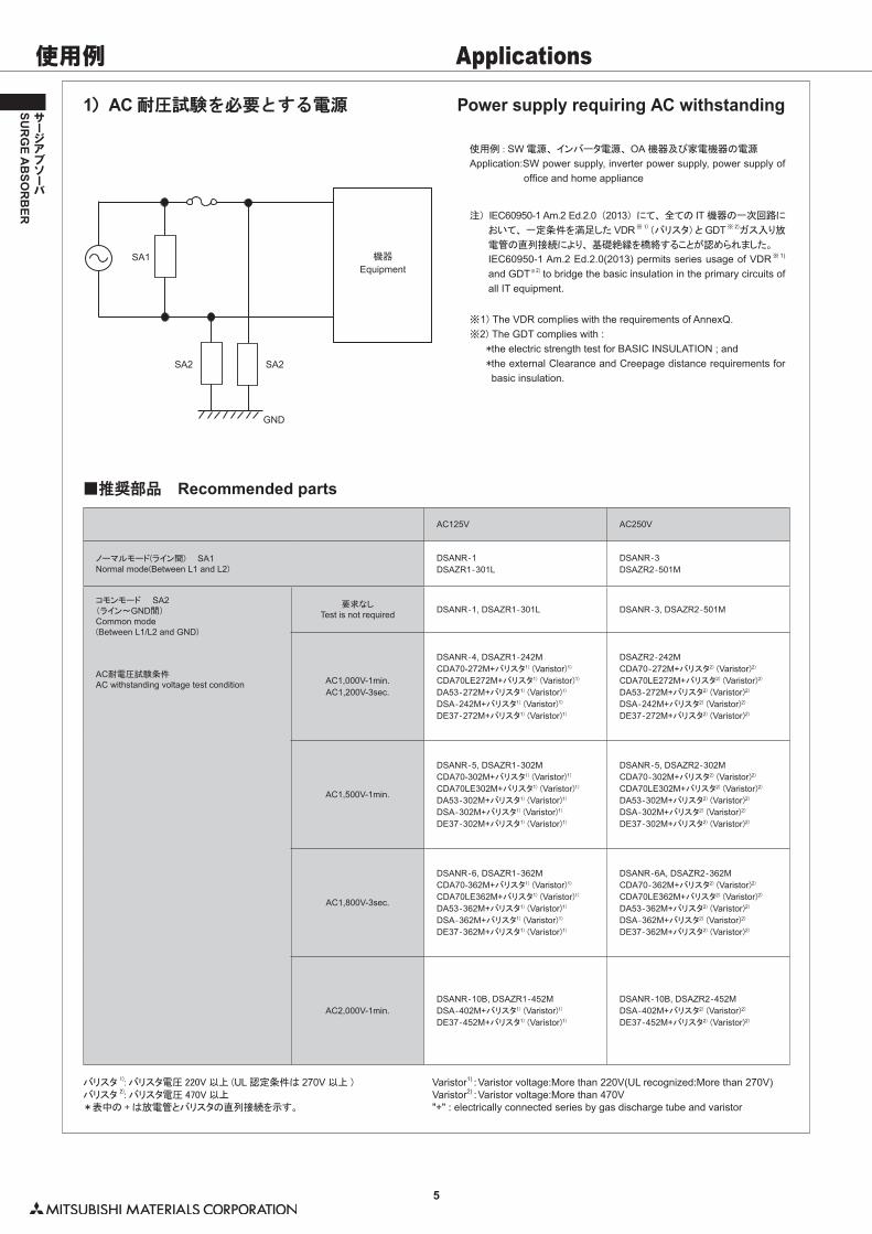
1)AC 耐圧試験を必要とする電源 Power supply requiring AC withstanding
使用例�:�SW 電源、 インバータ電源、 OA 機器及び家電機器の電源
■推奨部品 Recommended parts
Application:SW power supply, inverter power supply, power supply of office and home appliance
注) IEC60950-1 Am.2 Ed.2.0 (2013) にて、 全ての IT 機器の一次回路に
おいて、 一定条件を満足した VDR※1) (バリスタ)と GDT※2)ガス入り放
電管の直列接続により、 基礎絶縁を橋絡することが認められました。
IEC60950-1 Am.2 Ed.2.0(2013) permits series usage of VDR※ 1) and GDT※ 2) to bridge the basic insulation in the primary circuits of all IT equipment.
※1)�The VDR complies with the requirements of AnnexQ.※2) The GDT complies with :� *the electric strength test for BASIC INSULATION ; and� *�the external Clearance and Creepage distance requirements for
basic insulation.
Varistor1) : Varistor voltage:More than 220V(UL recognized:More than 270V)Varistor2) : Varistor voltage:More than 470V"+" : electrically connected series by gas discharge tube and varistor
バリスタ 1): バリスタ電圧 220V以上 (UL 認定条件は 270V 以上 )バリスタ 2): バリスタ電圧 470V以上*表中の +は放電管とバリスタの直列接続を示す。
AC125V AC250V
ノーマルモード(ライン間) SA1Normal mode(Between L1 and L2)
DSANR‐1DSAZR1‐301L
DSANR‐3DSAZR2‐501M
コモンモード SA2(ライン~GND間)Common mode(Between L1/L2 and GND)
AC耐電圧試験条件AC withstanding voltage test condition
要求なしTest is not required DSANR‐1, DSAZR1‐301L DSANR‐3, DSAZR2‐501M
AC1,000V-1min.AC1,200V-3sec.
DSANR‐4, DSAZR1‐242MCDA70-272M+バリスタ1)�(Varistor)1)
CDA70LE272M+バリスタ1)�(Varistor)1)
DA53‐272M+バリスタ1)�(Varistor)1)
DSA‐242M+バリスタ1)�(Varistor)1)
DE37‐272M+バリスタ1)�(Varistor)1)
DSAZR2‐242MCDA70‐272M+バリスタ2)�(Varistor)2)
CDA70LE272M+バリスタ2)�(Varistor)2)
DA53‐272M+バリスタ2)�(Varistor)2)
DSA‐242M+バリスタ2)�(Varistor)2)
DE37‐272M+バリスタ2)�(Varistor)2)
AC1,500V-1min.
DSANR‐5, DSAZR1‐302MCDA70-302M+バリスタ1)�(Varistor)1)
CDA70LE302M+バリスタ1)�(Varistor)1)
DA53‐302M+バリスタ1)�(Varistor)1)
DSA‐302M+バリスタ1)�(Varistor)1)
DE37‐302M+バリスタ1)�(Varistor)1)
DSANR‐5, DSAZR2‐302MCDA70‐302M+バリスタ2)�(Varistor)2)
CDA70LE302M+バリスタ2)�(Varistor)2)
DA53‐302M+バリスタ2)�(Varistor)2)
DSA‐302M+バリスタ2)�(Varistor)2)
DE37‐302M+バリスタ2)�(Varistor)2)
AC1,800V-3sec.
DSANR‐6, DSAZR1‐362MCDA70-362M+バリスタ1)�(Varistor)1)
CDA70LE362M+バリスタ1)�(Varistor)1)
DA53‐362M+バリスタ1)�(Varistor)1)
DSA‐362M+バリスタ1)�(Varistor)1)
DE37‐362M+バリスタ1)�(Varistor)1)
DSANR‐6A, DSAZR2‐362MCDA70‐362M+バリスタ2)�(Varistor)2)
CDA70LE362M+バリスタ2)�(Varistor)2)
DA53‐362M+バリスタ2)�(Varistor)2)
DSA‐362M+バリスタ2)�(Varistor)2)
DE37‐362M+バリスタ2)�(Varistor)2)
AC2,000V-1min.DSANR‐10B, DSAZR1‐452MDSA‐402M+バリスタ1)�(Varistor)1)
DE37‐452M+バリスタ1)�(Varistor)1)
DSANR‐10B, DSAZR2‐452MDSA‐402M+バリスタ2)�(Varistor)2)
DE37‐452M+バリスタ2)�(Varistor)2)
SA2
SA1
SA2
GND
Equipment機器
使用例 Applications
6
SUR
GE A
BSO
RB
ER
サージアブソーバ
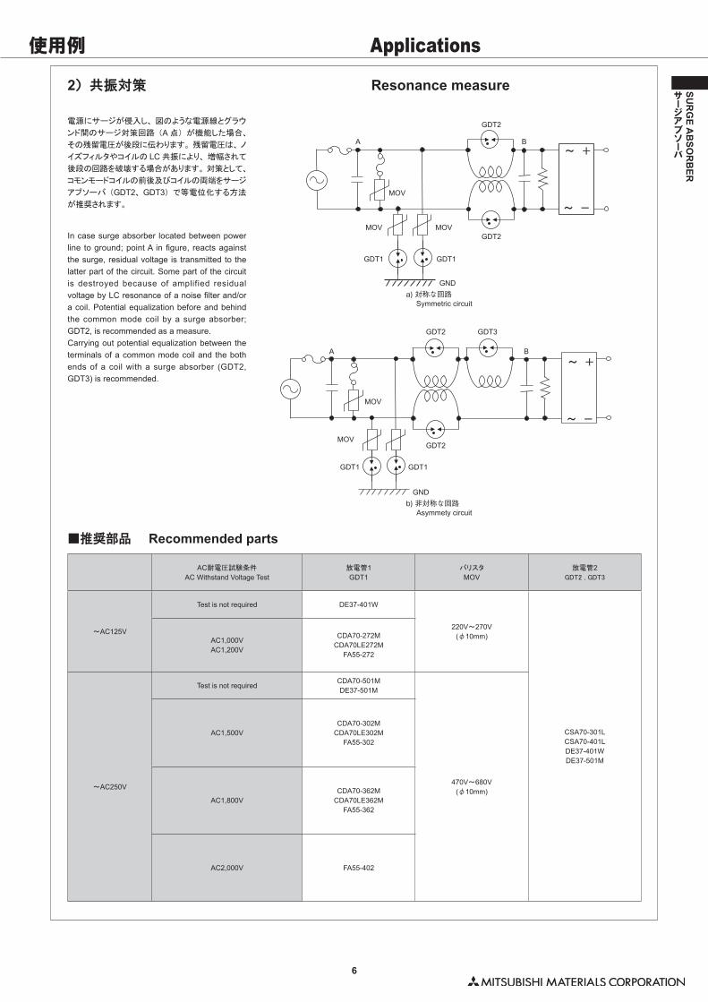
2)共振対策 Resonance measure
電源にサージが侵入し、 図のような電源線とグラウ
ンド間のサージ対策回路 (A 点) が機能した場合、
その残留電圧が後段に伝わります。 残留電圧は、 ノ
イズフィルタやコイルの LC 共振により、 増幅されて
後段の回路を破壊する場合があります。 対策として、
コモンモードコイルの前後及びコイルの両端をサージ
アブソーバ (GDT2、 GDT3) で等電位化する方法
が推奨されます。
■推奨部品 Recommended parts
In case surge absorber located between power line to ground; point A in figure, reacts against the surge, residual voltage is transmitted to the latter part of the circuit. Some part of the circuit is destroyed because of amplified residual voltage by LC resonance of a noise filter and/or a coil. Potential equalization before and behind the common mode coil by a surge absorber; GDT2, is recommended as a measure. Carrying out potential equalization between the terminals of a common mode coil and the both ends of a coil with a surge absorber (GDT2, GDT3) is recommended.
AC耐電圧試験条件
AC Withstand Voltage Test放電管1GDT1
バリスタ
MOV放電管2
GDT2�,�GDT3
~AC125V
Test is not required DE37-401W
220V~270V(φ10mm)
CSA70-301LCSA70-401LDE37-401WDE37-501M
AC1,000VAC1,200V
CDA70-272MCDA70LE272M
FA55-272
~AC250V
Test is not requiredCDA70-501MDE37-501M
470V~680V(φ10mm)
AC1,500VCDA70-302M
CDA70LE302MFA55-302
AC1,800VCDA70-362M
CDA70LE362MFA55-362
AC2,000V FA55-402
GDT1
GDT1GDT1
GND
GND
GDT2
GDT2
GDT2
GDT2 GDT3
BA
BA
MOV
MOV
MOV
MOV
MOV
GDT1
Symmetric circuita) 対称な回路
Asymmety circuitb) 非対称な回路
使用例 Applications
7
SUR
GE A
BSO
RB
ER
サージアブソーバ
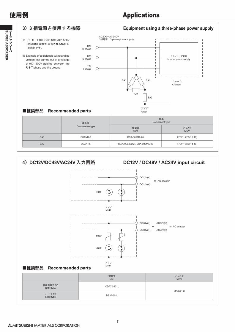
3)3 相電源を使用する機器 Equipment using a three-phase power supply
4)DC12V/DC48V/AC24V 入力回路 DC12V / DC48V / AC24V input circuit
※�(R ・ S ・ T 相)-GND 間に AC1,500V絶縁耐圧試験が実施される場合の
実施例です。
※ �Example of a dielectric withstanding voltage test carried out at a voltage of AC1,500V applied between the R.S.T phase and the ground.
GND
SA2SA1
SA1SA1
R phaseR相
Inverter power supplyインバータ電源
AC200~AC240V3相電源 3-phase power supply
Chassisシャーシ
S phaseS相
T phaseT相
■推奨部品 Recommended parts
複合品
Combination type
部品
Component type
放電管GDT
バリスタ
MOV
SA1 DSANR-3 DSA-501MA-05 220V~270V(φ10)
SA2 DSANR5 CDA70LE302M , DSA-302MA-05 470V~680V(φ10)
■推奨部品 Recommended parts放電管GDT
バリスタ
MOV
表面実装タイプ
SMD typeCDA70-301L
39V(φ10)リードタイプLead type DE37-301L
GND
GND
GDT
GDT
MOV
DC12V(+)
DC12V(+)to AC adapter
DC48V(+)
DC48V(+)
AC24V(+)
AC24V(+)to AC adapteror
使用例 Applications
8
SUR
GE A
BSO
RB
ER
サージアブソーバ
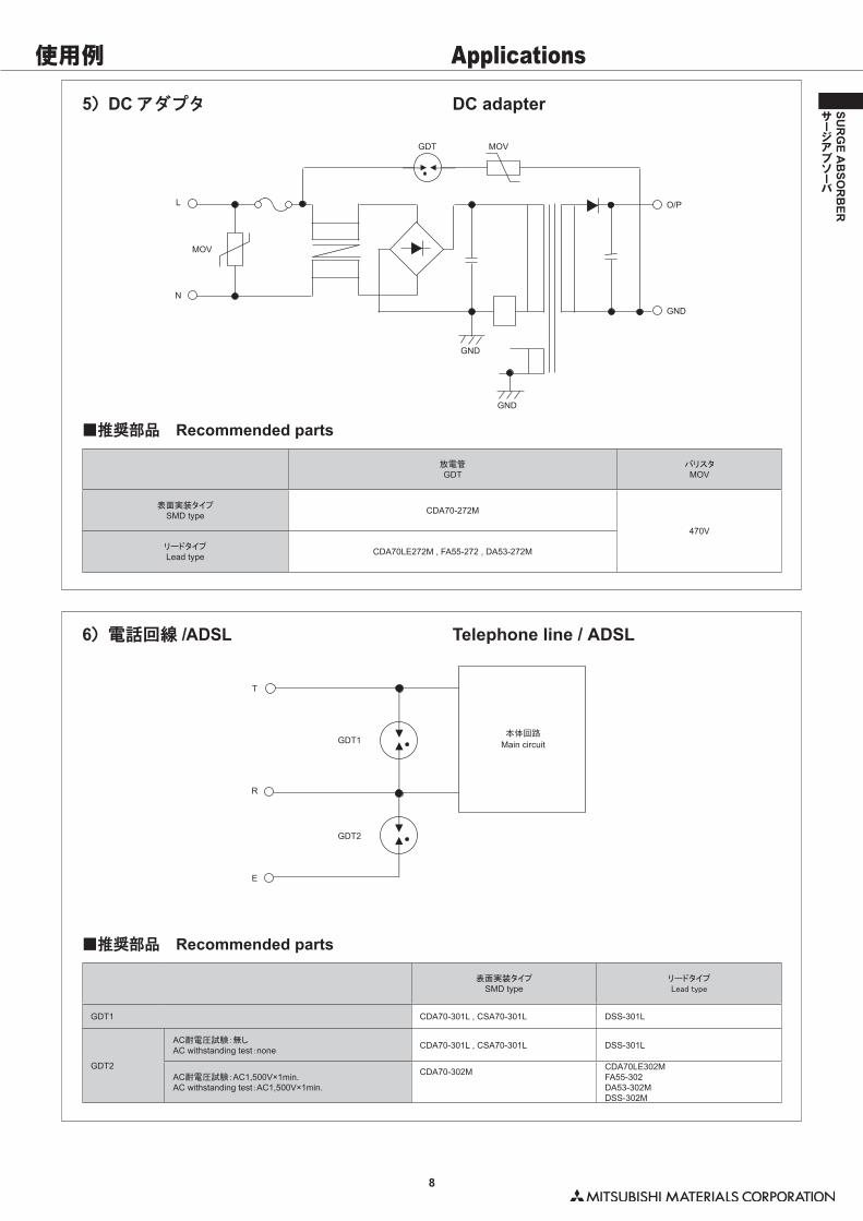
5)DC アダプタ DC adapter
6)電話回線 /ADSL Telephone line / ADSL
GND
GND
GND
GDT
O/P
MOV
MOV
L
N
GDT1
T
R
E
GDT2
Main circuit本体回路
■推奨部品 Recommended parts
放電管GDT
バリスタMOV
表面実装タイプSMD type CDA70-272M
470V
リードタイプLead type CDA70LE272M , FA55-272 , DA53-272M
■推奨部品 Recommended parts
表面実装タイプSMD type
リードタイプLead�type
GDT1 CDA70-301L , CSA70-301L DSS-301L
GDT2
AC耐電圧試験:無しAC withstanding test:none CDA70-301L , CSA70-301L DSS-301L
AC耐電圧試験:AC1,500V×1min.AC withstanding test:AC1,500V×1min.
CDA70-302M CDA70LE302MFA55-302DA53-302MDSS-302M
使用例 Applications
使用例 Applications
9
SUR
GE A
BSO
RB
ER
サージアブソーバ
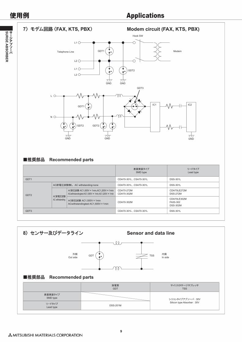
7)モデム回路(FAX, KTS, PBX) Modem circuit (FAX, KTS, PBX)
8)センサー及びデータライン Sensor and data line
■推奨部品 Recommended parts
表面実装タイプ
SMD typeリードタイプ
Lead type
GDT1 CDA70-301L , CSA70-301L DSS-301L
GDT2
AC耐電圧試験無し AC withstanding:none CDA70-301L , CSA70-301L DSS-301L
AC耐電圧試験
AC withstanding
AC耐圧試験�AC1,000V×1min,AC1,200V×1minACwithstandingtest AC1,000V×1min,AC1,200V×1min
CDA70-272MCDA70-302M
CDA70LE272MDSS-272M
AC耐圧試験�AC1,500V×1minACwithstandingtest AC1,500V×1min
CDA70-302MCDA70LE302MFA55-302DSS-302M
GDT3 CDA70-301L , CSA70-301L DSS-301L
GND
L1
L2
L1
L2
GND
GND
L
N
GDT1
GDT2
GDT2
GDT3
IC1 IC2
GDT2
GDT1
GND GND
Telephone Line
Hook SW
Modem
■推奨部品 Recommended parts放電管
GDTサイリスタサージサプレッサ
TSS
表面実装タイプ
SMD typeシリコンタイプアブソーバ�:�30VSilicon type Absorber : 30V
リードタイプ
Lead typeDSS-201M
GDT TSSOut side外側
In side内側
使用例 Applications
10
SUR
GE A
BSO
RB
ER
サージアブソーバ
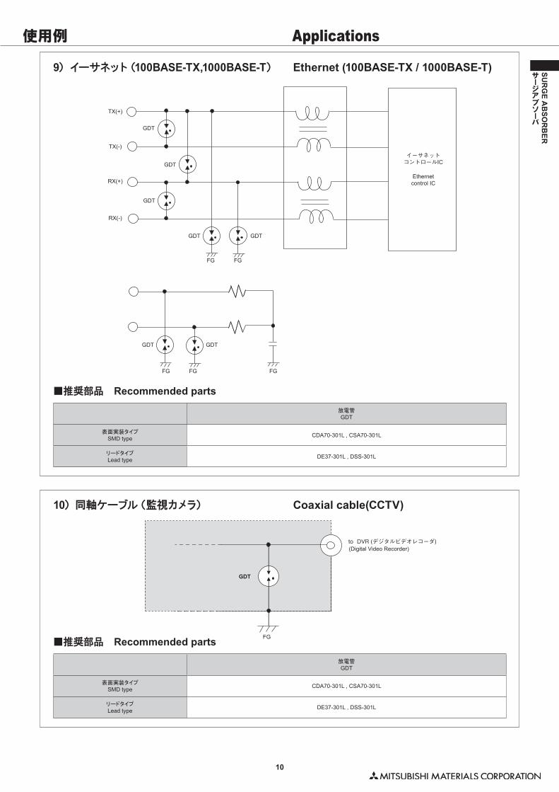
9)イーサネット(100BASE-TX,1000BASE-T) Ethernet (100BASE-TX / 1000BASE-T)
10)同軸ケーブル(監視カメラ) Coaxial cable(CCTV)
TX(+)
TX(-)
RX(+)
RX(-)
GDT
GDT
GDT
GDT
GDT GDT
FG FG
FG FG FG
GDT
Ethernetcontrol IC
イーサネットコントロールIC
FG
(Digital Video Recorder)to DVR (デジタルビデオレコーダ)
GDT
■推奨部品 Recommended parts放電管GDT
表面実装タイプSMD type CDA70-301L , CSA70-301L
リードタイプLead type DE37-301L , DSS-301L
■推奨部品 Recommended parts放電管GDT
表面実装タイプSMD type CDA70-301L , CSA70-301L
リードタイプLead type DE37-301L , DSS-301L
使用例 Applications
11
SUR
GE A
BSO
RB
ER
サージアブソーバ
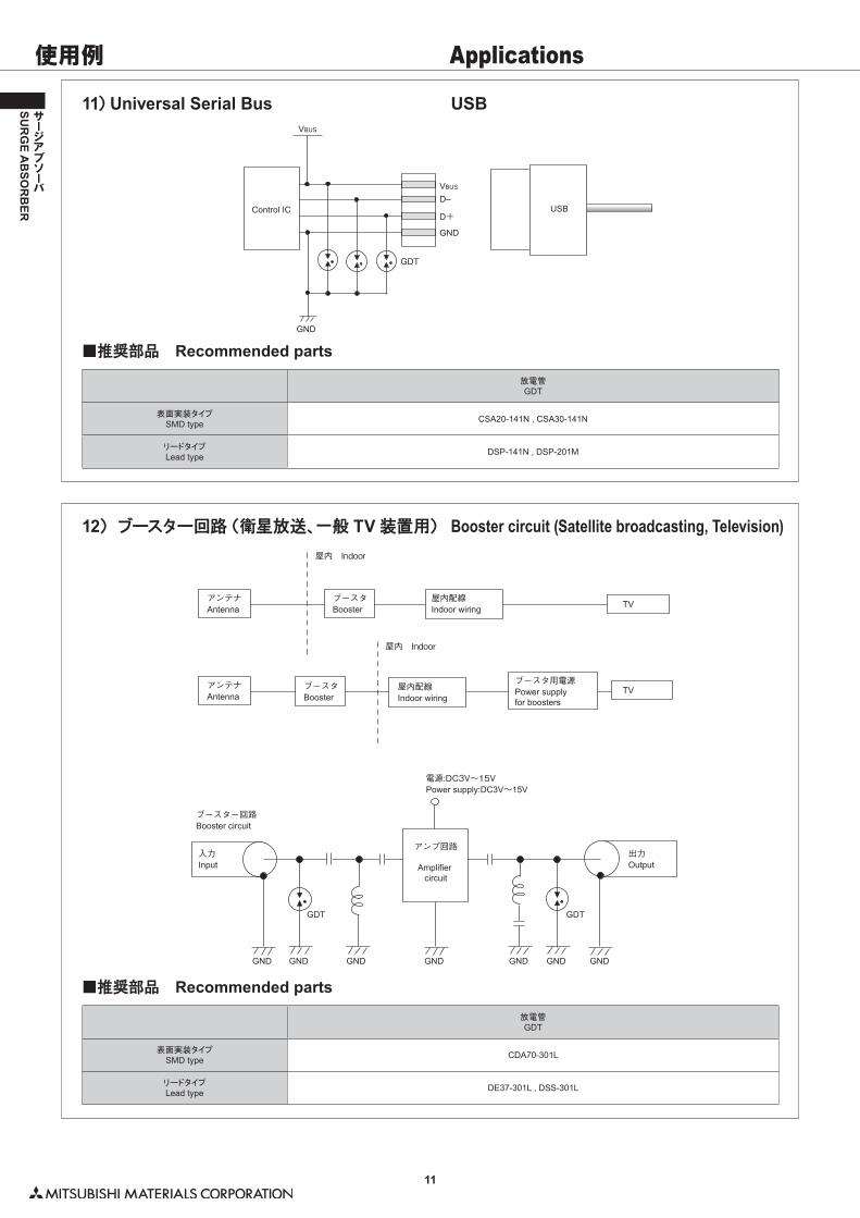
12)ブースター回路(衛星放送、一般 TV 装置用) Booster circuit (Satellite broadcasting, Television)
11)Universal Serial Bus USB
GND GND GND GND GND GND GND
GDT GDT
TV
TV
Antennaアンテナ
Antennaアンテナ
Input入力
Output出力
Boosterブースタ
Boosterブースタ
Indoor wiring屋内配線
Booster circuitブースター回路
Power supply:DC3V~15V電源:DC3V~15V
Indoor wiring屋内配線 Power supply
for boosters
ブースタ用電源
Amplifier circuit
アンプ回路
屋内 Indoor
屋内 Indoor
GND
GDT
USB
VBUS
VBUS
D–
D+
GND
Control IC
■推奨部品 Recommended parts放電管GDT
表面実装タイプSMD type CDA70-301L
リードタイプLead type DE37-301L , DSS-301L
■推奨部品 Recommended parts放電管GDT
表面実装タイプSMD type CSA20-141N , CSA30-141N
リードタイプLead type DSP-141N , DSP-201M
使用例 Applications
12
SUR
GE A
BSO
RB
ER
サージアブソーバ
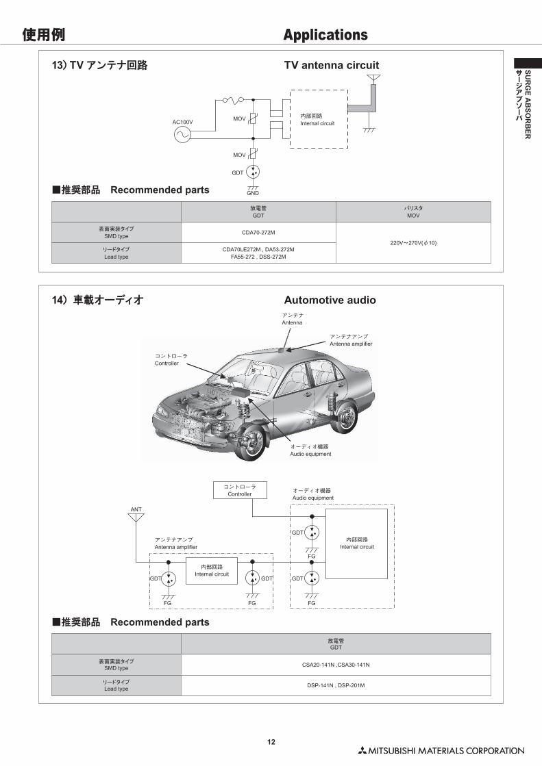
14)車載オーディオ Automotive audio
13)TV アンテナ回路 TV antenna circuit
ANT
GDT
GDTGDTGDT
FG FG FG
FG
Antennaアンテナ
Antenna amplifierアンテナアンプ
Antenna amplifierアンテナアンプ
Audio equipmentオーディオ機器
Audio equipmentオーディオ機器
Controllerコントローラ
Controllerコントローラ
Internal circuit内部回路
Internal circuit内部回路
■推奨部品 Recommended parts放電管
GDTバリスタ
MOV
表面実装タイプ
SMD typeCDA70-272M
220V~270V(φ10)リードタイプ
Lead typeCDA70LE272M , DA53-272M
FA55-272 , DSS-272M
GND
MOV
MOV
GDT
AC100V Internal circuit内部回路
■推奨部品 Recommended parts放電管GDT
表面実装タイプSMD type CSA20-141N ,CSA30-141N
リードタイプLead type DSP-141N , DSP-201M
使用例 Applications
13
SUR
GE A
BSO
RB
ER
サージアブソーバ
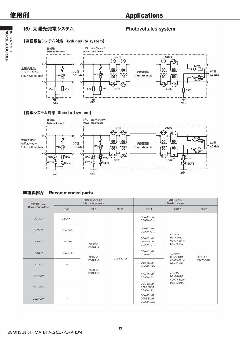
■推奨部品 Recommended parts
開放電圧 VocOpen circuit voltage
高信頼性システムHigh quality system
標準システムStandard system
SA1 SA2 GDT3 GDT1 GDT2 GDT3
DC100V DSAHR-1
AC125V:DSAHR-1
AC250V:DSAHR-3
AC400V:DSAHR-5
DA53-501M
DSA-301LACDA70-301M
AC125V:DE37-301LCDA70-301MDSA-301LA
AC250V:DE37-501MCDA70-501MDSA-501MA
AC400V:DE37-102MCDA70-102MDSA-102MA
DE37-301LCSA70-301L
DC250V DSAHR-3DSA-501MACDA70-501M
DC450V DSAHR-4DSA-701MADA53-701MCDA70-701M
DC600V DSAHR-5DSA-102MACDA70-102M
DC750V ―DSA-152MACDA70-152M
DC1,000V ―DSA-152MACDA70-152M
DC1,500V ―DSA-282MADA53-272MCDA70-272M
DC2,000V ―DSA-302MADA53-302MCDA70-302M
15)太陽光発電システム
【高信頼性システム対策 High quality system】
【標準システム対策 Standard system】
Photovoltaics system
DC側DC side
太陽光電池モジュールへSolar cell module
AC側AC side
GND
SA1
MOV
P
N
SA1
接続箱Distribution unit
パワーコンディショナーPower conditioner
内部回路Internal circuit
GDT3
GDT3
GDT3
GDT3 SA2SA1
MOV
SA1
MOV
MOV
GND GND
DC側DC side
太陽光電池モジュールへSolar cell module
AC側AC side
GND
MOV
GDT1
MOV
P
NMOV
GDT1
接続箱Distribution unit
パワーコンディショナーPower conditioner
内部回路Internal circuit
GDT3
GDT3
GDT3
GDT3GDT2
MOV
GDT1
MOV
MOV
GDT1
MOV
MOV
MOV
GND GND
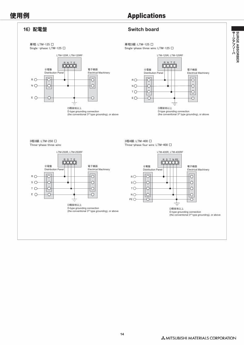
Distribution Panel分電盤
Electrical Machinery電子機器
Distribution Panel分電盤
Electrical Machinery電子機器
D-type grounding connection(the conventional 3rd type grounding), or above
D種接地以上D-type grounding connection(the conventional 3rd type grounding), or above
D種接地以上
R
N
E
R
N
T
E
R N T E
LTM-125R, LTM-125RF LTM-125R, LTM-125RF
Single –phase: LTM-125 □単相:LTM-125 □
Single-phase three wire: LTM-125 □単相3線:LTM-125 □
R N T E
Distribution Panel分電盤
Electrical Machinery電子機器
Distribution Panel分電盤
Electrical Machinery電子機器
D-type grounding connection(the conventional 3rd type grounding), or above
D種接地以上
D-type grounding connection(the conventional 3rd type grounding), or above
D種接地以上
R
S
E
T
R
S
T
N
PE
R S T E
LTM-250R, LTM-250RF LTM-400R, LTM-400RF
Three-phase three wire:3相3線:LTM-250 □
Three-phase four wire: LTM-400 □3相4線:LTM-400 □
R S T N PE
使用例 Applications
14
SUR
GE A
BSO
RB
ER
サージアブソーバ
16)配電盤 Switch board
技術資料 Technical Data
15
SUR
GE A
BSO
RB
ER
サージアブソーバ
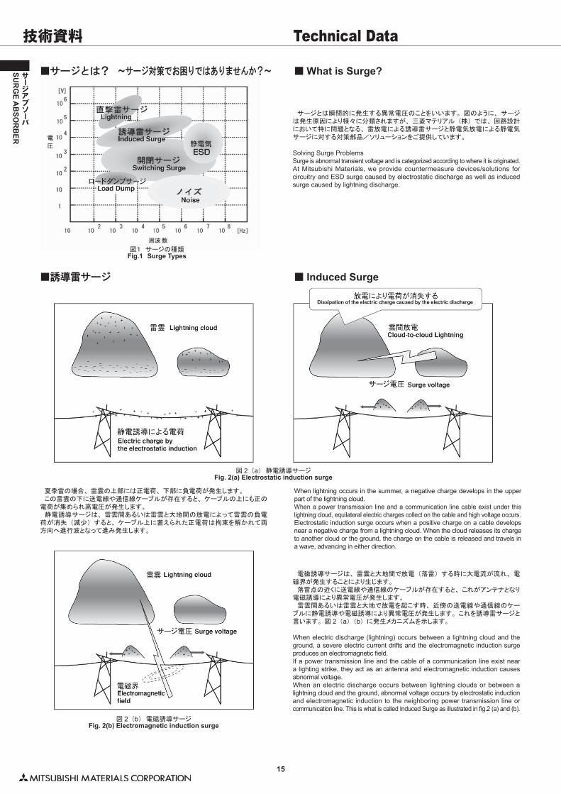
図1 サージの種類Fig.1 Surge Types
サージとは瞬間的に発生する異常電圧のことをいいます。 図のように、 サージは発生原因により様々に分類されますが、 三菱マテリアル (株) では、 回路設計において特に問題となる、 雷放電による誘導雷サージと静電気放電による静電気サージに対する対策部品/ソリューションをご提供しています。
Solving Surge ProblemsSurge is abnormal transient voltage and is categorized according to where it is originated.At Mitsubishi Materials, we provide countermeasure devices/solutions for circuitry and ESD surge caused by electrostatic discharge as well as induced surge caused by lightning discharge.
図 2 (b) 電磁誘導サージFig. 2(b) Electromagnetic induction surge
電磁誘導サージは、 雷雲と大地間で放電 (落雷) する時に大電流が流れ、 電磁界が発生することにより生じます。 落雷点の近くに送電線や通信線のケーブルが存在すると、 これがアンテナとなり電磁誘導により異常電圧が発生します。 � 雷雲間あるいは雷雲と大地で放電を起こす時、 近傍の送電線や通信線のケーブルに静電誘導や電磁誘導により異常電圧が発生します。 これを誘導雷サージと言います。 図 2 (a) (b) に発生メカニズムを示します。
When electric discharge (lightning) occurs between a lightning cloud and the ground, a severe electric current drifts and the electromagnetic induction surge produces an electromagnetic field.If a power transmission line and the cable of a communication line exist near a lighting strike, they act as an antenna and electromagnetic induction causes abnormal voltage.When an electric discharge occurs between lightning clouds or between a lightning cloud and the ground, abnormal voltage occurs by electrostatic induction and electromagnetic induction to the neighboring power transmission line or communication line. This is what is called Induced Surge as illustrated in fig.2 (a) and (b).
■誘導雷サージ
図 2 (a) 静電誘導サージFig. 2(a) Electrostatic induction surge
夏季雷の場合、 雷雲の上部には正電荷、 下部に負電荷が発生します。 この雷雲の下に送電線や通信線ケーブルが存在すると、 ケーブルの上にも正の電荷が集められ高電圧が発生します。 静電誘導サージは、 雷雲間あるいは雷雲と大地間の放電によって雷雲の負電荷が消失 (減少) すると、 ケーブル上に蓄えられた正電荷は拘束を解かれて両方向へ進行波となって進み発生します。 �
When lightning occurs in the summer, a negative charge develops in the upper part of the lightning cloud.When a power transmission line and a communication line cable exist under this lightning cloud, equilateral electric charges collect on the cable and high voltage occurs.Electrostatic induction surge occurs when a positive charge on a cable develops near a negative charge from a lightning cloud. When the cloud releases its charge to another cloud or the ground, the charge on the cable is released and travels in a wave, advancing in either direction.
■サージとは? ~サージ対策でお困りではありませんか?~ ■ What is Surge?
■ Induced Surge
技術資料 Technical Data
16
SUR
GE A
BSO
RB
ER
サージアブソーバ
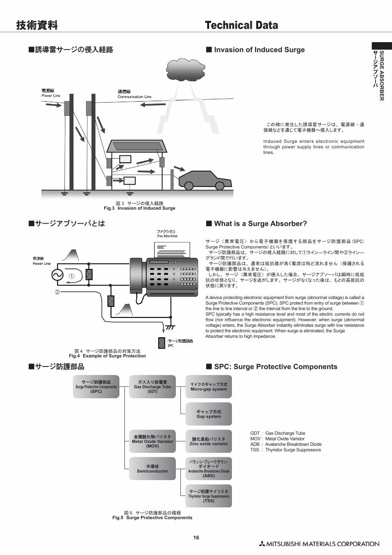
この様に発生した誘導雷サージは、 電源線 ・ 通信線などを通じて電子機器へ侵入します。
Induced Surge enters electronic equipment through power supply lines or communication lines.
図 4 サージ防護部品の対策方法Fig.4 Example of Surge Protection
図 5 サージ防護部品の種類Fig.5 Surge Protective Components
サージ (異常電圧) から電子機器を保護する部品をサージ防護部品 (SPC: Surge Protective Components) といいます。 サージ防護部品は、 サージの侵入経路に対して①ライン―ライン間や②ライン―グランド間で行います。 サージ防護部品は、 通常は抵抗値が高く電流は殆ど流れません (保護される電子機器に影響は与えません)。 しかし、 サージ (異常電圧) が侵入した場合、 サージアブソーバは瞬時に低抵抗の状態となり、 サージを逃がします。 サージがなくなった後は、 もとの高抵抗の状態に戻ります。
A device protecting electronic equipment from surge (abnormal voltage) is called a Surge Protective Components (SPC). SPC protect from entry of surge between ① the line to line interval or ② the interval from the line to the ground.SPC typically has a high resistance level and most of the electric currents do not flow (nor influence the electronic equipment). However; when surge (abnormal voltage) enters, the Surge Absorber instantly eliminates surge with low resistance to protect the electronic equipment. When surge is eliminated, the SurgeAbsorber returns to high impedance.
GDT : Gas Discharge TubeMOV : Metal Oxide VaristorADB : Avalanche Breakdown DiodeTSS : Thyristor Surge Suppressors
図 3 サージの侵入経路Fig.3 Invasion of Induced Surge
■誘導雷サージの侵入経路 ■ Invasion of Induced Surge
■ What is a Surge Absorber?
■ SPC: Surge Protective Components
■サージアブソーバとは
■サージ防護部品
サージ防護部品Surge Protective Components
(SPC)
ガス入り放電管Gas Discharge Tube
(GDT)マイクロギャップ方式Micro-gap system
ギャップ方式Gap system
酸化亜鉛バリスタZinc oxide varistor
バランシ・ブレークダウン・ダイオード
Avalanche Breakdown Diode(ABD)
サージ防護サイリスタThyristor Surge Suppressors
(TSS)
金属酸化物バリスタMetal Oxide Varistor
(MOV)
半導体Semiconductor
技術資料 Technical Data
17
SUR
GE A
BSO
RB
ER
サージアブソーバ
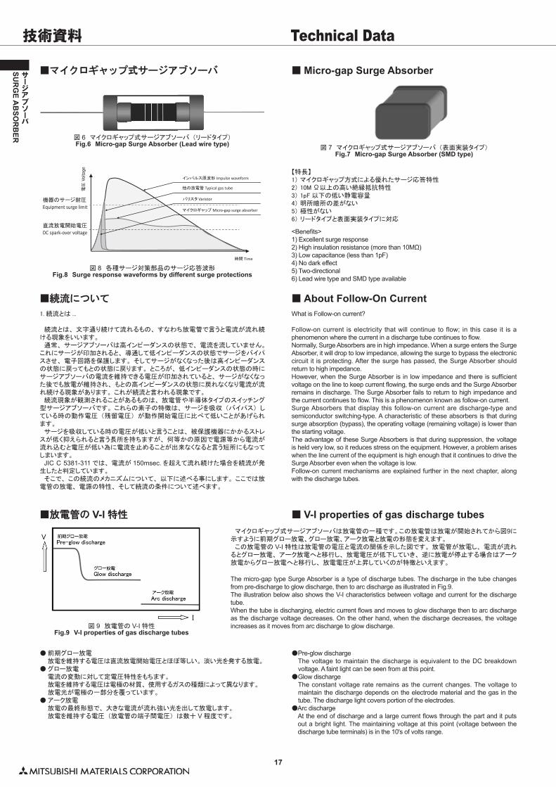
図 6 マイクロギャップ式サージアブソーバ (リードタイプ)Fig.6 Micro-gap Surge Absorber (Lead wire type)
図 7 マイクロギャップ式サージアブソーバ (表面実装タイプ)Fig.7 Micro-gap Surge Absorber (SMD type)
図 8 各種サージ対策部品のサージ応答波形Fig.8 Surge response waveforms by different surge protections
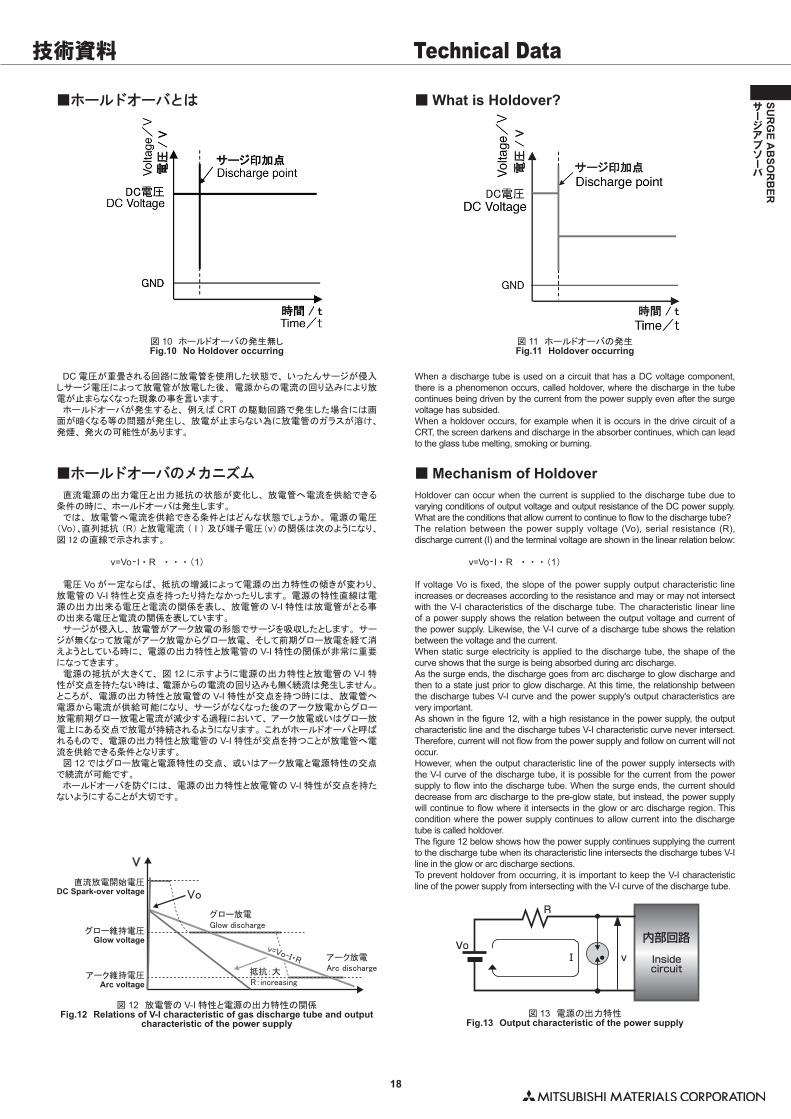
図 9 放電管の V-I 特性Fig.9 V-I properties of gas discharge tubes
【特長】1) マイクロギャップ方式による優れたサージ応答特性2) 10M Ω以上の高い絶縁抵抗特性3) 1pF 以下の低い静電容量4) 明所暗所の差がない5) 極性がない6) リードタイプと表面実装タイプに対応
<Benefits>1) Excellent surge response2) High insulation resistance (more than 10MΩ)3) Low capacitance (less than 1pF)4) No dark effect5) Two-directional6) Lead wire type and SMD type available
1. 続流とは ...
続流とは、 文字通り続けて流れるもの、 すなわち放電管で言うと電流が流れ続ける現象をいいます。 通常、 サージアブソーバは高インピーダンスの状態で、 電流を流していません。これにサージが印加されると、 導通して低インピーダンスの状態でサージをバイパスさせ、 電子回路を保護します。 そしてサージがなくなった後は高インピーダンスの状態に戻ってもとの状態に戻ります。 ところが、 低インピーダンスの状態の時にサージアブソーバの電流を維持できる電圧が印加されていると、 サージがなくなった後でも放電が維持され、 もとの高インピーダンスの状態に戻れなくなり電流が流れ続ける現象があります。 これが続流と言われる現象です。 続流現象が観測されることがあるものは、 放電管や半導体タイプのスイッチング型サージアブソーバです。 これらの素子の特徴は、 サージを吸収 (バイパス) している時の動作電圧 (残留電圧) が動作開始電圧に比べて低いことがあげられます。 サージを吸収している時の電圧が低いと言うことは、 被保護機器にかかるストレスが低く抑えられると言う長所を持ちますが、 何等かの原因で電源等から電流が流れ込むと電圧が低い為に電流を止めることが出来なくなると言う短所にもなってしまいます。 JIC C 5381-311 では、 電流が 150msec. を超えて流れ続けた場合を続流が発生したと判定しています。 そこで、 この続流のメカニズムについて、 以下に述べる事にします。 ここでは放電管の放電、 電源の特性、 そして続流の条件について述べます。
● 前期グロー放電 放電を維持する電圧は直流放電開始電圧とほぼ等しい。 淡い光を発する放電。● グロー放電 電流の変動に対して定電圧特性をもちます。 放電を維持する電圧は電極の材質、 使用するガスの種類によって異なります。 放電光が電極の一部分を覆っています。● アーク放電 放電の最終形態で、 大きな電流が流れ強い光を出して放電します。 放電を維持する電圧 (放電管の端子間電圧) は数十 V 程度です。
What is Follow-on current?
Follow-on current is electricity that will continue to flow; in this case it is a phenomenon where the current in a discharge tube continues to flow.Normally, Surge Absorbers are in high impedance. When a surge enters the Surge Absorber, it will drop to low impedance, allowing the surge to bypass the electronic circuit it is protecting. After the surge has passed, the Surge Absorber should return to high impedance.However, when the Surge Absorber is in low impedance and there is sufficient voltage on the line to keep current flowing, the surge ends and the Surge Absorber remains in discharge. The Surge Absorber fails to return to high impedance and the current continues to flow. This is a phenomenon known as follow-on current.Surge Absorbers that display this follow-on current are discharge-type and semiconductor switching-type. A characteristic of these absorbers is that during surge absorption (bypass), the operating voltage (remaining voltage) is lower than the starting voltage.The advantage of these Surge Absorbers is that during suppression, the voltage is held very low, so it reduces stress on the equipment. However, a problem arises when the line current of the equipment is high enough that it continues to drive the Surge Absorber even when the voltage is low.Follow-on current mechanisms are explained further in the next chapter, along with the discharge tubes.
マイクロギャップ式サージアブソーバは放電管の一種です。この放電管は放電が開始されてから図9に示すように前期グロー放電、グロー放電、アーク放電と放電の形態を変えます。 この放電管の V-I 特性は放電管の電圧と電流の関係を示した図です。 放電管が放電し、 電流が流れるとグロー放電、 アーク放電へと移行し、 放電電圧が低下していき、 逆に放電が停止する場合はアーク放電からグロー放電へと移行し、 放電電圧が上昇していくのが特徴といえます。
The micro-gap type Surge Absorber is a type of discharge tubes. The discharge in the tube changes from pre-discharge to glow discharge, then to arc discharge as illustrated in Fig.9.The illustration below also shows the V-I characteristics between voltage and current for the discharge tube.When the tube is discharging, electric current flows and moves to glow discharge then to arc discharge as the discharge voltage decreases. On the other hand, when the discharge decreases, the voltage increases as it moves from arc discharge to glow discharge.
●Pre-glow discharge The voltage to maintain the discharge is equivalent to the DC breakdown
voltage. A faint light can be seen from at this point.●Glow discharge The constant voltage rate remains as the current changes. The voltage to
maintain the discharge depends on the electrode material and the gas in the tube. The discharge light covers portion of the electrodes.
●Arc discharge At the end of discharge and a large current flows through the part and it puts
out a bright light. The maintaining voltage at this point (voltage between the discharge tube terminals) is in the 10's of volts range.
■マイクロギャップ式サージアブソーバ
■続流について ■ About Follow-On Current
■ V-I properties of gas discharge tubes
■ Micro-gap Surge Absorber
■放電管の V-I 特性
バリスタ Varistor
他の放電管 Typical gas tube
インパルス原波形 Impulse waveform
マイクロギャップ Micro-gap surge absorber
時間 Time
直流放電開始電圧
DC spark-over voltage
機器のサージ耐圧
Equipment surge limit
電圧
Volta
ge
技術資料 Technical Data
18
SUR
GE A
BSO
RB
ER
サージアブソーバ
DC 電圧が重畳される回路に放電管を使用した状態で、 いったんサージが侵入しサージ電圧によって放電管が放電した後、 電源からの電流の回り込みにより放電が止まらなくなった現象の事を言います。 ホールドオーバが発生すると、 例えば CRT の駆動回路で発生した場合には画面が暗くなる等の問題が発生し、 放電が止まらない為に放電管のガラスが溶け、発煙、 発火の可能性があります。
When a discharge tube is used on a circuit that has a DC voltage component, there is a phenomenon occurs, called holdover, where the discharge in the tube continues being driven by the current from the power supply even after the surge voltage has subsided.When a holdover occurs, for example when it is occurs in the drive circuit of a CRT, the screen darkens and discharge in the absorber continues, which can lead to the glass tube melting, smoking or burning.
図 10 ホールドオーバの発生無しFig.10 No Holdover occurring
図 11 ホールドオーバの発生Fig.11 Holdover occurring
R
Vo内部回路Insidecircuit
Ⅰ v
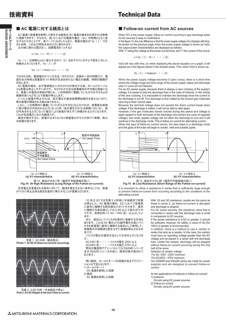
直流電源の出力電圧と出力抵抗の状態が変化し、 放電管へ電流を供給できる条件の時に、 ホールドオーバは発生します。 では、 放電管へ電流を供給できる条件とはどんな状態でしょうか。 電源の電圧(Vo)、直列抵抗 (R) と放電電流 (�I�) 及び端子電圧(v)の関係は次のようになり、図 12 の直線で示されます。
� v=Vo- I ・ R ・ ・ ・ (1)
電圧 Vo が一定ならば、 抵抗の増減によって電源の出力特性の傾きが変わり、放電管の V-I 特性と交点を持ったり持たなかったりします。 電源の特性直線は電源の出力出来る電圧と電流の関係を表し、 放電管の V-I 特性は放電管がとる事の出来る電圧と電流の関係を表しています。 サージが侵入し、放電管がアーク放電の形態でサージを吸収したとします。 サージが無くなって放電がアーク放電からグロー放電、 そして前期グロー放電を経て消えようとしている時に、 電源の出力特性と放電管の V-I 特性の関係が非常に重要になってきます。 電源の抵抗が大きくて、 図 12 に示すように電源の出力特性と放電管の V-I 特性が交点を持たない時は、電源からの電流の回り込みも無く続流は発生しません。ところが、 電源の出力特性と放電管の V-I 特性が交点を持つ時には、 放電管へ電源から電流が供給可能になり、 サージがなくなった後のアーク放電からグロー放電前期グロー放電と電流が減少する過程において、 アーク放電或いはグロー放電上にある交点で放電が持続されるようになります。 これがホールドオーバと呼ばれるもので、 電源の出力特性と放電管の V-I 特性が交点を持つことが放電管へ電流を供給できる条件となります。 図 12 ではグロー放電と電源特性の交点、 或いはアーク放電と電源特性の交点で続流が可能です。 ホールドオーバを防ぐには、 電源の出力特性と放電管の V-I 特性が交点を持たないようにすることが大切です。
Holdover can occur when the current is supplied to the discharge tube due to varying conditions of output voltage and output resistance of the DC power supply. What are the conditions that allow current to continue to flow to the discharge tube? The relation between the power supply voltage (Vo), serial resistance (R), discharge current (I) and the terminal voltage are shown in the linear relation below:
� v=Vo- I ・ R ・ ・ ・ (1)
If voltage Vo is fixed, the slope of the power supply output characteristic line increases or decreases according to the resistance and may or may not intersect with the V-I characteristics of the discharge tube. The characteristic linear line of a power supply shows the relation between the output voltage and current of the power supply. Likewise, the V-I curve of a discharge tube shows the relation between the voltage and the current. When static surge electricity is applied to the discharge tube, the shape of the curve shows that the surge is being absorbed during arc discharge. As the surge ends, the discharge goes from arc discharge to glow discharge and then to a state just prior to glow discharge. At this time, the relationship between the discharge tubes V-I curve and the power supply's output characteristics are very important. As shown in the figure 12, with a high resistance in the power supply, the output characteristic line and the discharge tubes V-I characteristic curve never intersect. Therefore, current will not flow from the power supply and follow on current will not occur. However, when the output characteristic line of the power supply intersects with the V-I curve of the discharge tube, it is possible for the current from the power supply to flow into the discharge tube. When the surge ends, the current should decrease from arc discharge to the pre-glow state, but instead, the power supply will continue to flow where it intersects in the glow or arc discharge region. This condition where the power supply continues to allow current into the discharge tube is called holdover. The figure 12 below shows how the power supply continues supplying the current to the discharge tube when its characteristic line intersects the discharge tubes V-I line in the glow or arc discharge sections. To prevent holdover from occurring, it is important to keep the V-I characteristic line of the power supply from intersecting with the V-I curve of the discharge tube.直流放電開始電圧
DC Spark-over voltage
グロー維持電圧Glow voltage
アーク維持電圧Arc voltage
グロー放電Glow discharge
アーク放電Arc discharge抵抗:大
R:increasing
V
Vo
v=Vo-I・R
図 12 放電管の V-I 特性と電源の出力特性の関係Fig.12 Relations of V-I characteristic of gas discharge tube and output
characteristic of the power supply図 13 電源の出力特性
Fig.13 Output characteristic of the power supply
■ホールドオーバとは
■ホールドオーバのメカニズム ■ Mechanism of Holdover
■ What is Holdover?
19
SUR
GE A
BSO
RB
ER
サージアブソーバ
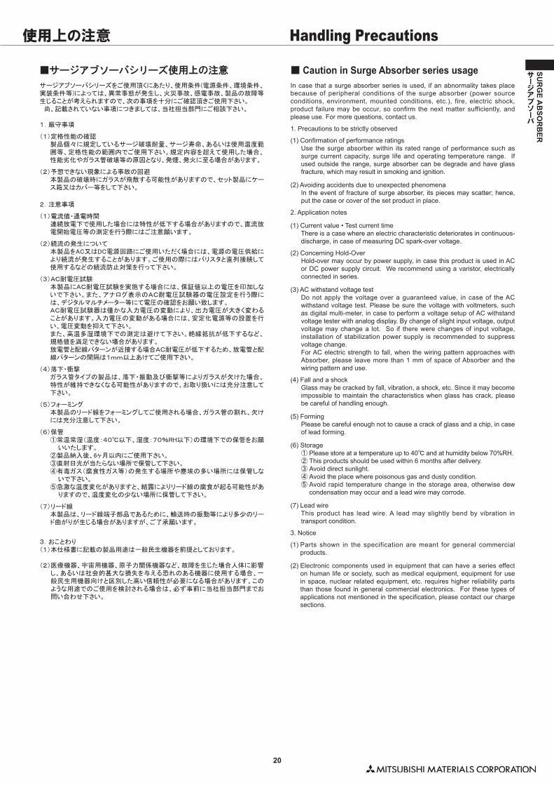
■ AC 電源に対する続流とは ■ Follow-on current from AC sources AC 電源に放電管を使用して発生する続流は DC 電源の場合を応用すれば簡単に理解できます。 すなわち、 図 12 における電源の電圧 (Vo) が時間とともに変化するだけのことです。 前ページにも示したとおり、 電源の電圧が Vo (� t�) で示される時、 この出力特性は次のように表されます。 出力端に現れる電圧を v、 回路電流を I とすると
�� v=Vo ( t ) -R ・ I ・ ・ ・ (2)
Vo ( t ) は時間とともに変化するので (2) 式をグラフに示すと下図左に示した斜線のようになります。 Vo ( t ) が
� Vo ( t ) =Vosin ω t ・ ・ ・ (3)
で示される時、 電源電圧が 0 になる点�(ゼロクロス) 近傍の一定の時間だけ、 電源の出力特性と放電管の V-I 特性が交点を持たない電圧の範囲、 時間の範囲が存在します。 AC 電源の場合、 必ず電源電圧にゼロクロスが発生する為、 ホールドオーバよりも放電は停止しやすいのです。 ゼロクロス付近は放電維持の不可能な領域になり、 放電への電流の供給が絶たれ、 この時間内に電離していたガス分子がもとの絶縁状態にもどることで放電が停止します。 いったん放電が停止すれば、 端子電圧が直流放電開始電圧を超えないので、再び放電が開始される事はありません。 しかし、 この時間内に電離していたガス分子がなくならなければ、 放電管の両端に再び電圧が印加されるようになった時�(逆の電圧がかかる周期にはいる)、 再び印加されるようになった電圧により放電が消えずに持続されるようになります。これが交流電圧における続流です。 続流が発生すると、 放電が止まらなくなり放電管のガラスが溶けて発煙、 発火の危険があります。
1Ω 及び 3Ω では写真 2 と同様に半端続流で放電は停止した。 AC 電源の場合、 DC に比べて放電管に直列に接続する抵抗値は小さくてすみます。 直列に接続する抵抗値としては 0.5Ω 以上であれば十分ですが、 余裕を持って 3Ω (100V 系) 以上としています。 また、 抵抗としてバリスタを直列に接続する方法もあります。 これは AC 電圧よりも動作電圧の高いバリスタを放電管に直列に接続する抵抗として使用して、放電管の半波続流も発生せずに放電を停止させる方法です。 バリスタ電圧の選定方法としては次のようになります。 AC100V 系 ・ ・ ・ ・ バリスタ電圧 220V 以上 AC200V 系 ・ ・ ・ ・ バリスタ電圧 470V 以上 弊社の電源用アブソーバとしては DSANR シリーズ及び DSAZR シリーズがあり、 続流対策が施されております。
特に続流、 ホールドオーバの危険があるアプリケーションは下記となります。1) ホールドオーバ �DC 電源を使用した回路2) 続流 �AC 電源を使用した回路
When DC is the power supply, follow-on current occurring in gas discharge tubes for AC sources is easy to understand. In the figure 12, the only difference is that the power supply voltage (Vo) changes with time. As shown on the previous page, when the power supply voltage is shown as Vo(t), the output power characteristics are displayed as follows: With “v” being the voltage at the power out terminal, and “I” the current of the circuit,
�� v=Vo ( t ) -R ・ I ・ ・ ・ (2)
Vo(t) will vary with time, so when displaying the above equation on a graph, it will appear as in the figures below in the shaded areas. Then when Vo(t) is shown as:
�� Vo ( t ) =Vosinωt ・ ・ ・ (3)
When the power supply voltage becomes 0 (zero cross), there is a short time where the voltage range and time range of the power supply output and discharge tube V-I curve do not intersect. For an AC power supply, because there is always a zero crossing of the supply's voltage, it is easier to stop the discharge than in the case of holdover. In the vicinity of the zero crossing, it is impossible to maintain the discharge since the current to the discharge is cut off. The discharge is then halted by the ionized gas molecules returning to their normal state. Because the terminal voltage does not exceed the direct current break down voltage, if the discharge is halted, it will not be able to start again. However, if the gas molecules remain ionized during this period and voltage is again applied to both terminals of the discharge tube (enters the cycle of opposite voltage), this newly applied voltage will not allow the discharge to end and it will continue in the discharge mode. This is follow-on current for alternating current. When this type of follow-on current occurs, the tube stays in a discharge mode and the glass of the tube will begin to smoke, melt and possibly ignite.
With 1Ω and 3Ω resistance, results are the same as those in photo 2, as follow-on-current is disrupted and discharge is stopped.For AC power sources, the resistance value that is connected in series with the discharge tube is small in comparison to DC sources.If the series resistance is 0.5Ω or greater, it should be sufficient; however, for safety, a value of 3Ω (for 100V) or greater is recommended.In addition, there is a method to use a varistor in series that acts as a resistor. In this case, the varistor must have an operating voltage greater than the AC voltage and be placed in a series with the discharge tube. Unlike the resistor, discharge will be stopped without follow-on current occurring during the first half of the wave.Selection of varistor voltage: For AC 100V - 220V minimum For AC200V - 470V minimumOur DSANR and DSAZR series are made for power supplies and are designed to prevent follow-on current.
At risk applications of holdover or follow-on-current:1) Holdover Circuits using DC power sources2) Follow-on current Circuits using AC power sources
交流電圧を重畳される条件に於いて、 続流を発生させない条件としては、 放電が十分に停止出来る抵抗を直列に挿入することが重要となります。
It is important to utilize a resistance in series that is sufficiently large enough to prevent follow-on-current from occurring according to the conditions of the alternating current.
(a)�V-I 特性上(a) V-I characteristics
(a)�V-I 特性上(a) V-I characteristics
(b)�V-t 特性上(b) V-t characteristics
(b)�V-t 特性上(b) V-t characteristics
図 14 抵抗が大きい時 (続流不可能領域が長い)Fig.14 At High Resistance (Long Range of No Follow-on-current)
図 15 抵抗が小さい時 (続流不可能領域が短い)Fig.15 At Low Resistance (Short Range of No Follow-on-current)
写真 1 0Ω の時 (続流発生)Photo 1 At 0Ω (Follow-on-current occurring)
写真 2 0.5Ω の時 (半波続流で停止)Photo 2 At 0.5Ω (Stopped at half wave Follow-on-current)
技術資料 Technical Data
20
SUR
GE A
BSO
RB
ER
サージアブソーバ
■サージアブソーバシリーズ使用上の注意 ■ Caution in Surge Absorber series usageサージアブソーバシリーズをご使用頂くにあたり、使用条件(電源条件、環境条件、実装条件等)によっては、異常事態が発生し、火災事故、感電事故、製品の故障等生じることが考えられますので、次の事項を十分にご確認頂きご使用下さい。 尚、記載されていない事項につきましては、当社担当部門にご相談下さい。
1.厳守事項
(1)定格性能の確認製品個々に規定しているサージ破壊耐量、サージ寿命、あるいは使用温度範囲等、定格性能の範囲内でご使用下さい。規定内容を超えて使用した場合、性能劣化やガラス管破壊等の原因となり、発煙、発火に至る場合があります。
(2)予想できない現象による事故の回避本製品の破壊時にガラスが飛散する可能性がありますので、セット製品にケース箱又はカバー等をして下さい。
2.注意事項
(1)電流値・通電時間連続放電下で使用した場合には特性が低下する場合がありますので、直流放電開始電圧等の測定を行う際にはご注意願います。
(2)続流の発生について本製品をAC又はDC電源回路にご使用いただく場合には、電源の電圧供給により続流が発生することがあります。ご使用の際にはバリスタと直列接続して使用するなどの続流防止対策を行って下さい。
(3)AC耐電圧試験本製品にAC耐電圧試験を実施する場合には、保証値以上の電圧を印加しないで下さい。また、アナログ表示のAC耐電圧試験器の電圧設定を行う際には、デジタルマルチメーター等にて電圧の確認をお願い致します。AC耐電圧試験器は僅かな入力電圧の変動により、出力電圧が大きく変わることがあります。入力電圧の変動がある場合には、安定化電源等の設置を行い、電圧変動を抑えて下さい。また、高温多湿環境下での測定は避けて下さい。絶縁抵抗が低下するなど、規格値を満足できない場合があります。放電管と配線パターンが近接する場合AC耐電圧が低下するため、放電管と配線パターンの間隔は1mm以上あけてご使用下さい。
(4)落下・衝撃ガラス管タイプの製品は、落下・振動及び衝撃等によりガラスが欠けた場合、特性が維持できなくなる可能性がありますので、お取り扱いには充分注意して下さい。
(5)フォーミング本製品のリード線をフォーミングしてご使用される場合、ガラス管の割れ、欠けには充分注意して下さい。
(6)保管①常温常湿(温度:40℃以下、湿度:70%RH以下)の環境下での保管をお願
いいたします。②製品納入後、6ヶ月以内にご使用下さい。③直射日光が当たらない場所で保管して下さい。④有毒ガス(腐食性ガス等)の発生する場所や塵埃の多い場所には保管しな
いで下さい。⑤急激な温度変化がありますと、結露によりリード線の腐食が起る可能性があ
りますので、温度変化の少ない場所に保管して下さい。
(7)リード線本製品は、リード線端子部品であるために、輸送時の振動等により多少のリード曲がりが生じる場合がありますが、ご了承願います。
3.おことわり(1)本仕様書に記載の製品用途は一般民生機器を前提としております。
(2)�医療機器、宇宙用機器、原子力関係機器など、故障を生じた場合人体に影響し、あるいは社会的甚大な損失を与える恐れのある機器に使用する場合、一般民生用機器向けと区別した高い信頼性が必要になる場合があります。このような用途でのご使用を検討される場合は、必ず事前に当社担当部門までお問い合わせ下さい。
In case that a surge absorber series is used, if an abnormality takes place because of peripheral conditions of the surge absorber (power source conditions, environment, mounted conditions, etc.), fire, electric shock, product failure may be occur, so confirm the next matter sufficiently, and please use. For more questions, contact us.
1. Precautions to be strictly observed
(1) Confirmation of performance ratingsUse the surge absorber within its rated range of performance such as surge current capacity, surge life and operating temperature range. If used outside the range, surge absorber can be degrade and have glass fracture, which may result in smoking and ignition.
(2) Avoiding accidents due to unexpected phenomenaIn the event of fracture of surge absorber, its pieces may scatter; hence, put the case or cover of the set product in place.
2. Application notes
(1) Current value • Test current timeThere is a case where an electric characteristic deteriorates in continuous-discharge, in case of measuring DC spark-over voltage.
(2) Concerning Hold-OverHold-over may occur by power supply, in case this product is used in AC or DC power supply circuit. We recommend using a varistor, electrically connected in series.
(3) AC withstand voltage testDo not apply the voltage over a guaranteed value, in case of the AC withstand voltage test. Please be sure the voltage with voltmeters, such as digital multi-meter, in case to perform a voltage setup of AC withstand voltage tester with analog display. By change of slight input voltage, output voltage may change a lot. So if there were changes of input voltage, installation of stabilization power supply is recommended to suppress voltage change. For AC electric strength to fall, when the wiring pattern approaches with Absorber, please leave more than 1 mm of space of Absorber and the wiring pattern and use.
(4) Fall and a shockGlass may be cracked by fall, vibration, a shock, etc. Since it may become impossible to maintain the characteristics when glass has crack, please be careful of handling enough.
(5) FormingPlease be careful enough not to cause a crack of glass and a chip, in case of lead forming.
(6) Storage① �Please store at a temperature up to 40℃ and at humidity below 70%RH.② �This products should be used within 6 months after delivery.③ �Avoid direct sunlight.④ �Avoid the place where poisonous gas and dusty condition.⑤ �Avoid rapid temperature change in the storage area, otherwise dew
condensation may occur and a lead wire may corrode.
(7) Lead wireThis product has lead wire. A lead may slightly bend by vibration in transport condition.
3. Notice
(1) Parts shown in the specification are meant for general commercial products.
(2) Electronic components used in equipment that can have a series effect on human life or society, such as medical equipment, equipment for use in space, nuclear related equipment, etc. requires higher reliability parts than those found in general commercial electronics. For these types of applications not mentioned in the specification, please contact our charge sections.
使用上の注意 Handling Precautions
21
SUR
GE A
BSO
RB
ER
サージアブソーバ
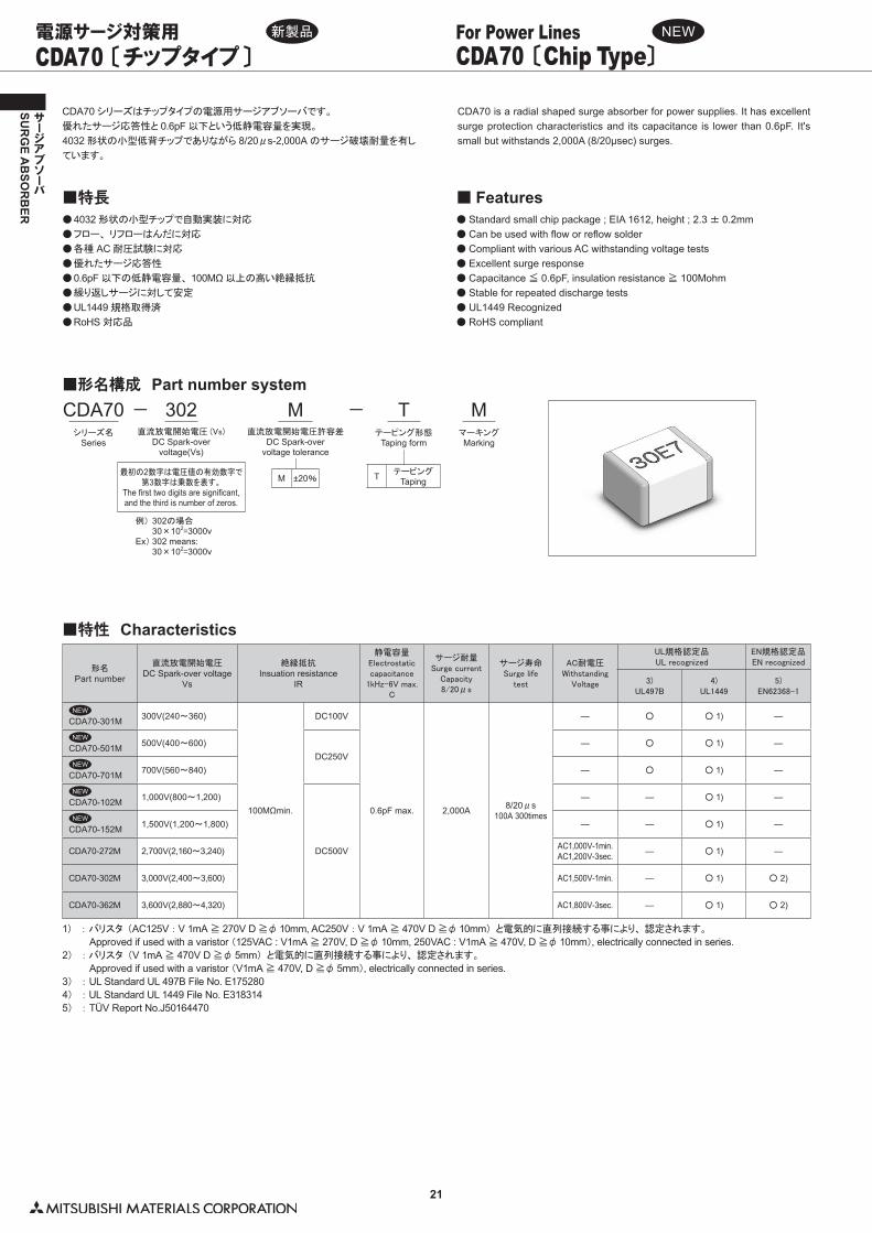
CDA70 シリーズはチップタイプの電源用サージアブソーバです。
優れたサージ応答性と 0.6pF 以下という低静電容量を実現。
4032 形状の小型低背チップでありながら 8/20μs-2,000A のサージ破壊耐量を有し
ています。
●�4032 形状の小型チップで自動実装に対応
●�フロー、 リフローはんだに対応
●�各種 AC 耐圧試験に対応
●�優れたサージ応答性
●�0.6pF 以下の低静電容量、 100MΩ 以上の高い絶縁抵抗
●�繰り返しサージに対して安定
●�UL1449 規格取得済
●�RoHS 対応品
■特長
■形名構成 Part number system
CDA70 is a radial shaped surge absorber for power supplies. It has excellent surge protection characteristics and its capacitance is lower than 0.6pF. It's small but withstands 2,000A (8/20μsec) surges.
●��Standard small chip package ; EIA 1612, height ; 2.3 ± 0.2mm●��Can be used with flow or reflow solder●��Compliant with various AC withstanding voltage tests●��Excellent surge response●��Capacitance ≦ 0.6pF, insulation resistance ≧ 100Mohm●��Stable for repeated discharge tests●��UL1449 Recognized●��RoHS compliant
■ Features
■特性 Characteristics
形名Part number
直流放電開始電圧DC Spark-over voltage
Vs
絶縁抵抗Insuation resistance
IR
静電容量Electrostatic�capacitance1kHz-6V�max.
C
サージ耐量Surge�current
Capacity8/20μs
サージ寿命Surge�life
test
AC耐電圧Withstanding
Voltage
UL規格認定品UL�recognized
EN規格認定品EN�recognized
3)UL497B
4)UL1449
5)EN62368-1
CDA70-301M 300V(240〜360)
100MΩmin.
DC100V
0.6pF max. 2,000A 8/20μs100A 300times
― ○ ○�1) ―
CDA70-501M 500V(400〜600)DC250V
― ○ ○�1) ―
CDA70-701M 700V(560〜840) ― ○ ○�1) ―
CDA70-102M 1,000V(800〜1,200)
DC500V
― ― ○�1) ―
CDA70-152M 1,500V(1,200〜1,800) ― ― ○�1) ―
CDA70-272M 2,700V(2,160〜3,240) AC1,000V-1min.AC1,200V-3sec. ― ○�1) ―
CDA70-302M 3,000V(2,400〜3,600) AC1,500V-1min. ― ○�1) ○�2)
CDA70-362M 3,600V(2,880〜4,320) AC1,800V-3sec. ― ○�1) ○�2)
CDA70 〔チップタイプ〕 CDA70 〔Chip Type〕For Power Lines電源サージ対策用
1) :��バリスタ (AC125V : V 1mA ≧ 270V D ≧φ 10mm, AC250V : V 1mA ≧ 470V D ≧φ 10mm) と電気的に直列接続する事により、 認定されます。
Approved if used with a varistor (125VAC : V1mA ≧ 270V, D ≧φ 10mm, 250VAC : V1mA ≧ 470V, D ≧φ 10mm), electrically connected in series.2) : �バリスタ (V 1mA ≧ 470V D ≧φ 5mm) と電気的に直列接続する事により、 認定されます。
Approved if used with a varistor (V1mA ≧ 470V, D ≧φ 5mm), electrically connected in series.3) :�UL Standard UL 497B File No. E1752804) : UL Standard UL 1449 File No. E3183145) :�TÜV Report No.J50164470
新製品 NEW
302直流放電開始電圧 (Vs)
DC Spark-overvoltage(Vs)
CDA70シリーズ名
Series
MマーキングMarking
M ±20%
M直流放電開始電圧許容差
DC Spark-overvoltage tolerance
最初の2数字は電圧値の有効数字で第3数字は乗数を表す。
The first two digits are significant,and the third is number of zeros.
例)�302の場合� 30×102=3000vEx) 302 means:� 30×102=3000v
−
T テーピングTaping
Tテーピング形態
Taping form
−
NEW
NEW
NEW
NEW
NEW
22
SUR
GE A
BSO
RB
ER
サージアブソーバ
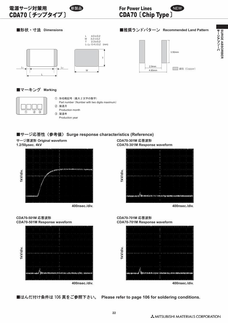
① :形名略記号 (最大 2 文字の数字)
� Part number (Number with two digits maximum)
② : 製造月
� Production month③ :製造年
� Production year
■形状・寸法 Dimensions
■サージ応答性(参考値) Surge response characteristics (Reference)
■推奨ランドパターン Recommended Land PatternL 4.0±0.2 W 3.2±0.2T 2.3±0.2L1.L2 0.4±0.2 (mm)
4.85mm
2.9mm
3.50mm
銅箔(Copper)
T
W
L
L2L1
CDA70 〔チップタイプ〕 CDA70 〔Chip Type〕For Power Lines電源サージ対策用
■はんだ付け条件は 106 頁をご参照下さい。 Please refer to page 106 for soldering conditions.
■マーキング Marking
①
サージ原波形 Original waveform1.2/50μsec. 4kV
CDA70-501M 応答波形CDA70-501M Response waveform
CDA70-301M 応答波形CDA70-301M Response waveform
CDA70-701M 応答波形CDA70-701M Response waveform
1kV/
div.
400nsec./div.
1kV/
div.
400nsec./div.
1kV/
div.
400nsec./div.
1kV/
div.
400nsec./div.
新製品 NEW
② ③
23
SUR
GE A
BSO
RB
ER
サージアブソーバ
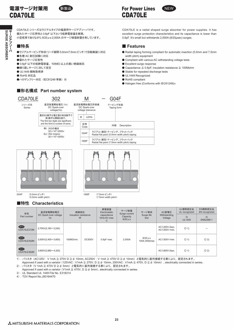
CDA70LE シリーズはラジアルタイプの電源用サージアブソーバです。
優れたサージ応答性と 0.6pF 以下という低静電容量を実現。
小型低背でありながら 8/20μs-2,000A のサージ破壊耐量を有しています。
●ラジアルテーピング形状(リード線間 5.0mm/7.5mm ピッチ)で自動実装に対応
●各種 AC 耐圧試験に対応
●優れたサージ応答性
● 0.6pF 以下の低静電容量、 100MΩ 以上の高い絶縁抵抗
●繰り返しサージに対して安定
● UL1449 規格取得済
● RoHS 対応品
●ハロゲンフリー対応 (IEC61249 準拠) ※
■特長
■形名構成 Part number system
CDA70LE is a radial shaped surge absorber for power supplies. It has excellent surge protection characteristics and its capacitance is lower than 0.6pF. It's small but withstands 2,000A (8/20μsec) surges.
● Radial taping forming compliant for automatic insertion (5.0mm and 7.5mm width pitch) equipment
● Compliant with various AC withstanding voltage tests● Excellent surge response● Capacitance ≦ 0.6pF, insulation resistance ≧ 100Mohm● Stable for repeated discharge tests ● UL1449 Recognized● RoHS compliant● Halogen free (Conforms with IEC61249)※
■ Features
CDA70LE CDA70LEFor Power Lines電源サージ対策用
■特性 Characteristics
形名Part number
直流放電開始電圧DC Spark-over voltage
Vs
絶縁抵抗Insuation resistance
IR
静電容量Electrostatic capacitance
1kHz-6V max.C
サージ耐量Surge current
Capacity8/20μs
サージ寿命Surge life
test
AC耐電圧Withstanding
Voltage
UL規格認定品UL recognized
EN規格認定品EN recognized
3)UL1449
4)EN62368-1
CDA70LE272M 2,700V(2,160〜3,240)
100MΩmin. DC500V 0.6pF max. 2,000A 8/20μs100A 300times
AC1,200V-3sec.AC1,000V-1min. ○�1) ―
CDA70LE302M 3,000V(2,400〜3,600) AC1,500V-1min. ○�1) ○�2)
CDA70LE362M 3,600V(2,880〜4,320) AC1,800V-3sec. ○�1) ○�2)
1) : �バリスタ (AC125V : V 1mA ≧ 270V D ≧φ 10mm, AC250V : V 1mA ≧ 470V D ≧φ 10mm) と電気的に直列接続する事により、 認定されます。
� Approved if used with a varistor (125VAC : V1mA ≧ 270V, D ≧φ 10mm, 250VAC�:�V1mA ≧ 470V, D ≧φ 10mm) , electrically connected in series.2) : バリスタ (V 1mA ≧ 470V D ≧φ 5mm) と電気的に直列接続する事により、 認定されます。
� Approved if used with a varistor (V1mA ≧ 470V, D ≧φ 5mm), electrically connected in series.3) : UL Standard UL 1449 File No. E3183144) : TÜV Report No.J50164470
新製品 NEW
NEW
NEW
NEW
302直流放電開始電圧 (Vs)
DC Spark-overvoltage(Vs)
CDA70LEシリーズ名
Series
M ±20%
M直流放電開始電圧許容差
DC Spark-overvoltage tolerance
最初の2数字は電圧値の有効数字で第3数字は乗数を表す。
The first two digits are significant,and the third is number of zeros.
例)�302の場合� 30×102=3000vEx) 302 means:� 30×102=3000v
− G04Fテーピング形態
Taping form
記号Code 内容 Description
G04F ラジアル(縦型)テーピング、フラットパックRadial flat pack (5.0mm width pitch) taping
H06F ラジアル(縦型)テーピング、フラットパックRadial flat pack (7.5mm width pitch) taping
H06FG04F (7.5mm ピッチ)(7.5mm width pitch)
(5.0mm ピッチ)(5.0mm width pitch)
24
SUR
GE A
BSO
RB
ER
サージアブソーバ
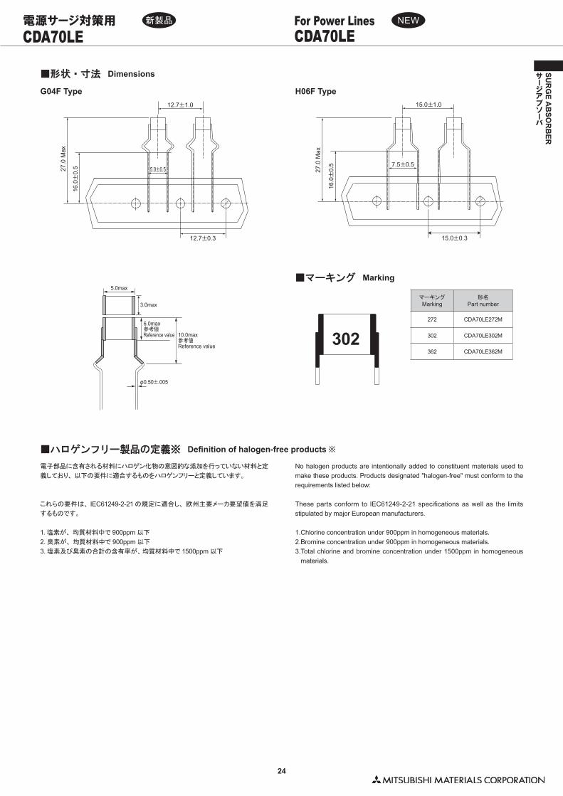
電子部品に含有される材料にハロゲン化物の意図的な添加を行っていない材料と定
義しており、 以下の要件に適合するものをハロゲンフリーと定義しています。
これらの要件は、 IEC61249-2-21 の規定に適合し、 欧州主要メーカ要望値を満足
するものです。
1. 塩素が、 均質材料中で 900ppm 以下
2. 臭素が、 均質材料中で 900ppm 以下
3. 塩素及び臭素の合計の含有率が、�均質材料中で 1500ppm 以下
No halogen products are intentionally added to constituent materials used to make these products. Products designated "halogen-free" must conform to the requirements listed below:
These parts conform to IEC61249-2-21 specifications as well as the limits stipulated by major European manufacturers.
1.Chlorine concentration under 900ppm in homogeneous materials.2.Bromine concentration under 900ppm in homogeneous materials.3. Total chlorine and bromine concentration under 1500ppm in homogeneous
materials.
■形状・寸法 Dimensions
■ハロゲンフリー製品の定義※ Definition of halogen-free products ※
12.7±1.0
12.7±0.3
5.0±0.5
16.0±
0.527
.0 M
ax
15.0±1.0
7.5±0.5
16.0±
0.5
27.0
Max
15.0±0.3
CDA70LE CDA70LEFor Power Lines電源サージ対策用
G04F Type H06F Type
マーキングMarking
形名Part number
272 CDA70LE272M
302 CDA70LE302M
362 CDA70LE362M
■マーキング Marking
302
3.0max
6.0max参考値Reference value 10.0max
参考値Reference value
φ0.50±.005
5.0max
新製品 NEW
25
SUR
GE A
BSO
RB
ER
サージアブソーバ
FA55 FA55For Power Lines電源サージ対策用
G04F
A22F
H06F
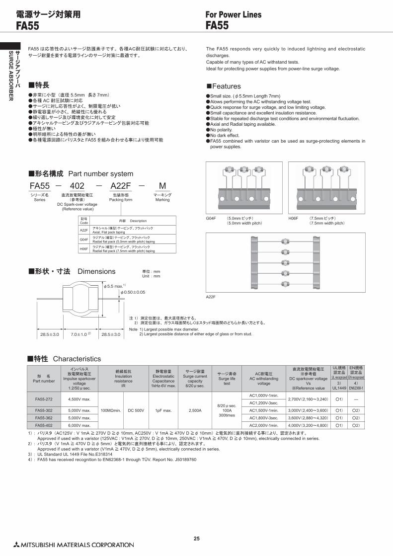
FA55 は応答性のよいサージ防護素子です。 各種AC耐圧試験に対応しており、
サージ耐量を要する電源ラインのサージ対策に最適です。
●非常に小型 (直径 5.5mm 長さ 7mm)●各種 AC 耐圧試験に対応●サージに対し応答性がよく、 制限電圧が低い●静電容量が小さく、 絶縁性にも優れる●繰り返しサージ及び環境変化に対して安定●アキシャルテーピング及びラジアルテーピング包装対応可能●極性が無い●明所暗所による特性の差が無い●各種電源回路にバリスタと FA55 を組み合わせる事により使用可能
■特長
■形名構成 Part number system
The FA55 responds very quickly to induced lightning and electrostatic discharges.Capable of many types of AC withstand tests.Ideal for protecting power supplies from power-line surge voltage.
● Small size. (φ5.5mm Length 7mm)● Alows performing the AC withstanding voltage test.● Quick response for surge voltage, and low limiting voltage.● Small capacitance and excellent insulation resistance.● Stable for repeated discharge test conditions and environmental fluctuation.● Axial and Radial taping available.● No polarity.● No dark effect.● FA55 combined with varistor can be used as surge-protecting elements in
power supplies.
■Features
402直流放電開始電圧
(参考値)DC Spark-over voltage
(Reference value)
FA55シリーズ名
Series
A22F包装形態
Packing form
MマーキングMarking
− − −
記号Code 内容 Description
A22F アキシャル(横型)テーピング、フラットパックAxial, Flat pack taping
G04F ラジアル(縦型)テーピング、フラットパックRadial flat pack (5.0mm width pitch) taping
H06F ラジアル(縦型)テーピング、フラットパックRadial flat pack (7.5mm width pitch) taping
注�1) 測定位置は、 最大直径部とする。� 2) 測定位置は、 ガラス端面間もしくはスタッド端面間のどちらか長い方とする。
Note 1) Largest possible max diameter. 2) Largest possible distance of either edge of glass or from stud.
■形状・寸法 Dimensions 単位�: mmUnit : mm
φ5.5 max.1)
φ0.50±0.05
7.0±1.0 2)28.5±3.0 28.5±3.0
1)�:�バリスタ (AC125V : V 1mA ≧ 270V D ≧φ 10mm, AC250V : V 1mA ≧ 470V D ≧φ 10mm) と電気的に直列接続する事により、 認定されます。� � Approved if used with a varistor (125VAC : V1mA ≧ 270V, D ≧φ 10mm, 250VAC : V1mA ≧ 470V, D ≧φ 10mm), electrically connected in series.2)�:�バリスタ (V 1mA ≧ 470V D ≧φ 5mm) と電気的に直列接続する事により、 認定されます。� � Approved if used with a varistor (V1mA ≧ 470V, D ≧φ 5mm), electrically connected in series.3) : UL Standard UL 1449 File No.E3183144) : FA55 has received recognition to EN62368-1 through TÜV. Report No. J50189760
■特性 Characteristics
形 名Part number
インパルス放電開始電圧
Impulse sparkovervoltage
1.2/50μsec.
絶縁抵抗Insulationresistance
IR
静電容量ElectrostaticCapacitance
1kHz-6V max.
サージ耐量Surge current
capacity8/20μsec.
サージ寿命Surge life
test
AC耐電圧AC withstanding
voltage
直流放電開始電圧※参考値
DC sparkover voltageVs
※Reference value
UL規格認定品
UL recognized
EN規格認定品
EN recognized3)
UL14494)
EN62368-1
FA55-272 4,500V max.
100MΩmin. DC 500V 1pF max. 2,500A8/20μsec.
100A300times
AC1,000V-1min.2,700V(2,160〜3,240) ○1) ―
AC1,200V-3sec.
FA55-302 5,000V max. AC1,500V-1min. 3,000V(2,400〜3,600) ○1) ○2)
FA55-362 5,000V max. AC1,800V-3sec. 3,600V(2,880〜4,320) ○1) ○2)
FA55-402 6,000V max. AC2,000V-1min. 4,000V(3,200〜4,800) ○1) ○2)
(7.5mm ピッチ)(7.5mm width pitch)
(5.0mm ピッチ)(5.0mm width pitch)
26
SUR
GE A
BSO
RB
ER
サージアブソーバ
DA53 DA53For Power Lines電源サージ対策用
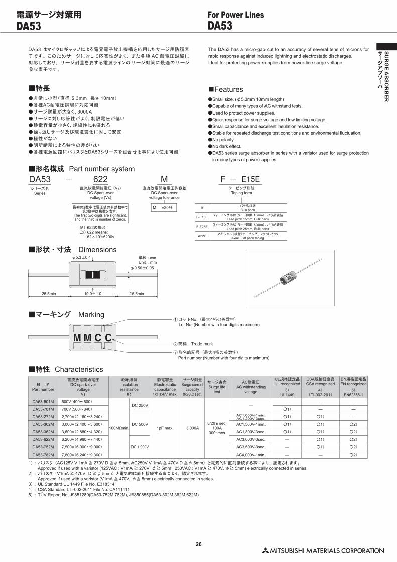
DA53 はマイクロギャップによる電界電子放出機構を応用したサージ用防護素
子です。 このためサージに対して応答性がよく、 また各種 AC 耐電圧試験に
対応しており、 サージ耐量を要する電源ラインのサージ対策に最適のサージ
吸収素子です。
●非常に小型(直径�5.3mm 長さ�10mm)
●各種AC耐電圧試験に対応可能
●サージ耐量が大きく、3000A●サージに対し応答性がよく、制限電圧が低い
●静電容量が小さく、絶縁性にも優れる
●繰り返しサージ及び環境変化に対して安定
●極性がない
●明所暗所による特性の差がない
●各種電源回路にバリスタとDA53シリーズを組合せる事により使用可能
■特長
The DA53 has a micro-gap cut to an accuracy of several tens of microns for rapid response against induced lightning and electrostatic discharges.Ideal for protecting power supplies from power-line surge voltage.
●�Small size. (φ5.3mm 10mm length)●�Capable of many types of AC withstand tests.●�Used to protect power supplies.●�Quick response for surge voltage and low limiting voltage.●�Small capacitance and excellent insulation resistance.●�Stable for repeated discharge test conditions and environmental fluctuation.●�No polarity.●�No dark effect.●�DA53 series surge absorber in series with a varistor used for surge protection
in many types of power supplies.
■Features
1)�:�バリスタ (AC125V V 1mA ≧ 270V D ≧φ 5mm, AC250V V 1mA ≧ 470V D ≧φ 5mm) と電気的に直列接続する事により、 認定されます。� � Approved if used with a varistor (125VAC : V1mA ≧ 270V, φ≧ 5mm ; 250VAC : V1mA ≧ 470V, φ≧ 5mm) electrically connected in series.2)�:�バリスタ (V1mA ≧ 470V D ≧φ 5mm) と電気的に直列接続する事により、 認定されます。� � Approved if used with a varistor (V1mA ≧ 470V, φ≧ 5mm) electrically connected in series.3)�:�UL Standard UL 1449 File No. E3183144)�:�CSA Standard LTI-002-2011 File No. CA1114115)�:�TÜV Report No. J9851289(DA53-752M,782M), J9850855(DA53-302M,362M,622M)
■特性 Characteristics
形 名Part number
直流放電開始電圧DC spark-over
voltageVs
絶縁抵抗Insulationresistance
IR
静電容量Electrostaticcapacitance
1kHz-6V max.
サージ耐量Surge current
capacity8/20μsec.
サージ寿命Surge life
test
AC耐電圧AC withstanding
voltage
UL規格認定品UL recognized
CSA規格認定品CSA recognized
EN規格認定品EN recognized
3)UL1449
4)LTI-002-2011
5)EN62368-1
DA53-501M 500V(400〜600)
100MΩmin.
DC 250V
1pF max. 3,000A8/20μsec.
100A300times
―― ― ―
DA53-701M 700V(560〜840) ○1) ― ―
DA53-272M 2,700V(2,160〜3,240)
DC 500V
AC1,000V-1min.AC1,200V-3sec. ○1) ○1) ―
DA53-302M 3,000V(2,400〜3,600) AC1,500V-1min. ○1) ○1) ○2)
DA53-362M 3,600V(2,880〜4,320) AC1,800V-3sec. ○1) ○1) ○2)
DA53-622M 6,200V(4,960〜7,440)
DC 1,000V
AC3,000V-3sec. ― ○1) ○2)
DA53-752M 7,500V(6,000〜9,000) AC3,600V-3sec. ― ○1) ○2)
DA53-782M 7,800V(6,240〜9,360) AC4,000V-1min. ― ― ○2)
■形名構成 Part number system622
直流放電開始電圧 (Vs)DC Spark-over
voltage (Vs)
DA53シリーズ名
Series
M ±20%
M直流放電開始電圧許容差
DC Spark-overvoltage tolerance
最初の2数字は電圧値の有効数字で第3数字は乗数を表す。
The first two digits are significant,and the third is number of zeros.
例)�622の場合Ex) 622 means:� 62×102=6200v
F −��E15Eテーピング形態
Taping form
−
B バラ品袋詰Bulk pack
F-E15E フォーミング形状(リード線間�15mm)、バラ品袋詰Lead pitch 15mm, Bulk pack
F-E25E フォーミング形状(リード線間�25mm)、バラ品袋詰Lead pitch 25mm, Bulk pack
A22F アキシャル(横型)テーピング、フラットパックAxial, Flat pack taping
■形状・寸法 Dimensions単位�: mmUnit : mm
25.5min
φ0.50±0.05
φ5.3±0.4
10.0±1.0 25.5min
■マーキング MarkingロットNo.(最大4桁の英数字)
形名略記号(最大4桁の英数字)
商標 Trade mark
Lot No. (Number with four digits maximum)
Part number (Number with four digits maximum)
27
SUR
GE A
BSO
RB
ER
サージアブソーバ
DSA DSAFor Power Lines電源サージ対策用
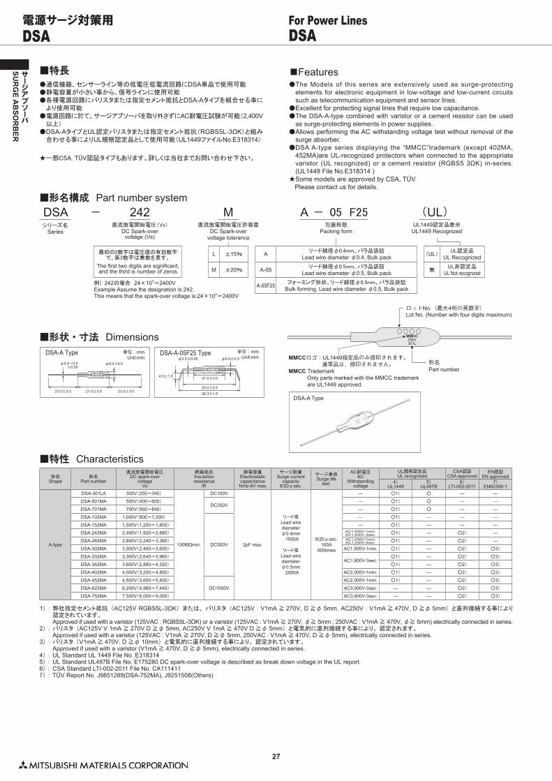
●�通信機器、センサーライン等の低電圧低電流回路にDSA単品で使用可能●�静電容量が小さい事から、信号ラインに使用可能●�各種電源回路にバリスタまたは指定セメント抵抗とDSA-Aタイプを組合せる事に
より使用可能●�電源回路に於て、サージアブソーバを取り外さずにAC耐電圧試験が可能(2,400V以上)
●�DSA-AタイプとUL認定バリスタまたは指定セメント抵抗(RGBS5L-3ΩK)と組み合わせる事によりUL規格認定品として使用可能(UL1449ファイルNo.E318314)
★�一部CSA,�TÜV認証タイプもあります。詳しくは当社までお問い合わせ下さい。
■特長●�The Models of this series are extensively used as surge-protecting
elements for electronic equipment in low-voltage and low-current circuits such as telecommunication equipment and sensor lines.
●�Excellent for protecting signal lines that require low capacitance.●�The DSA-A-type combined with varistor or a cement resistor can be used
as surge-protecting elements in power supplies.●�Allows performing the AC withstanding voltage test without removal of the
surge absorber.●�DSA A-type series displaying the “MMCC”trademark (except 402MA,
452MA)are UL-recognized protectors when connected to the appropriate varistor (UL recognized) or a cement resistor (RGBS5 3ΩK) in-series. (UL1449 File No.E318314 )
★�Some models are approved by CSA, TÜV.����Please contact us for details.
■Features
■形状・寸法 Dimensions
23.0±3.0 21.0±3.0 23.0±3.0
φ6.0±0.5φ0.4~0.5±0.05
単位:mmUnit:mm
DSA-A Type 単位:mm
26.3±1.525.0±0.5
21.0±3.0
φ0.5±0.05 φ6.0±0.5
4.5±1.0
Unit:mmDSA-A-05F25 Type
MMCCDSA301L
ロットNo.(最大4桁の英数字)
形名MMCCロゴ:UL1449指定品のみ捺印されます。 通常品は、捺印されません。
Lot No. (Number with four digits maximum)
Part numberMMCC Trademark Only parts marked with the MMCC trademark are UL1449 approved.
1)�:�弊社指定セメント抵抗 (AC125V RGBS5L-3ΩK) または、 バリスタ (AC125V : V1mA ≧ 270V, D ≧φ 5mm, AC250V : V1mA ≧ 470V, D ≧φ 5mm) と直列接続する事により認定されています。
� � Approved if used with a varistor (125VAC : RGBS5L-3ΩK) or a varistor (125VAC : V1mA ≧ 270V, φ≧ 5mm ; 250VAC : V1mA ≧ 470V, φ≧ 5mm) electrically connected in series.2)�:�バリスタ (AC125V V 1mA ≧ 270V D ≧φ 5mm, AC250V V 1mA ≧ 470V D ≧φ 5mm) と電気的に直列接続する事により、 認定されます。� � Approved if used with a varistor (125VAC : V1mA ≧ 270V, D ≧φ 5mm, 250VAC : V1mA ≧ 470V, D ≧φ 5mm), electrically connected in series.3)�:�バリスタ (V1mA ≧ 470V, D ≧φ 10mm) と電気的に直列接続する事により、 認定されています。� � Approved if used with a varistor (V1mA ≧ 470V, D ≧φ 5mm), electrically connected in series.4)�:�UL Standard UL 1449 File No. E3183145)�:�UL Standard UL497B File No. E175280 DC spark-over voltage is described as break down voltage in the UL report.6)�:�CSA Standard LTI-002-2011 File No. CA1114117)�:�TÜV Report No. J9851289(DSA-752MA), J9251508(Others)
■特性 Characteristics形状
Shape形名
Part number
直流放電開始電圧DC spark-over
voltageVs
絶縁抵抗Insulationresistance
lR
静電容量Electrostaticcapacitance
1kHz-6V max.
サージ耐量Surge current
capacity8/20μsec.
サージ寿命Surge life
test.
AC耐電圧AC
Withstandingvoltage
UL規格認定品UL recognized
CSA認証CSA approved
EN認証EN approved
4)UL1449
5)UL497B
6)LTI-002-2011
7)EN62368-1
A-type
DSA-301LA 300V(255〜345)
100MΩmin.
DC100V
2pF max.
リード径Lead wirediameterφ0.4mm:1500A
リード径Lead wirediameterφ0.5mm:2000A
8/20μsec.100A
300times
― ○1) ○ ― ―
DSA-501MA 500V(400〜600)DC250V
― ○1) ○ ― ―
DSA-701MA 700V(560〜840) ― ○1) ○ ― ―
DSA-102MA 1,000V(800〜1,200)
DC500V
― ○1) ― ― ―
DSA-152MA 1,500V(1,200〜1,800) ― ○1) ― ― ―
DSA-242MA 2,400V(1,920〜2,880) AC1,000V-1min.AC1,200V-3sec. ○1) ― ○2) ―
DSA-282MA 2,800V(2,240〜3,360) AC1,000V-1min.AC1,250V-3sec. ○1) ― ○2) ―
DSA-302MA 3,000V(2,400〜3,600) AC1,500V-1min. ○1) ― ○2) ○3)
DSA-332MA 3,300V(2,640〜3,960)AC1,800V-3sec.
○1) ― ○2) ○3)
DSA-362MA 3,600V(2,880〜4,320) ○1) ― ○2) ○3)
DSA-402MA 4,000V(3,200〜4,800) AC2,000V-1min. ○1) ― ○2) ○3)
DSA-452MA 4,500V(3,600〜5,400)
DC1000V
AC2,000V-1min. ○1) ― ○2) ○3)
DSA-622MA 6,200V(4,960〜7,440) AC3,000V-3sec. ― ― ○2) ○3)
DSA-752MA 7,500V(6,000〜9,000) AC3,600V-3sec. ― ― ○2) ○3)
■形名構成 Part number system242
直流放電開始電圧(Vs)DC Spark-over
voltage (Vs)
DSAシリーズ名
Series
M直流放電開始電圧許容差
DC Spark-overvoltage tolerance
A −��05��F25 (UL)包装形態
Packing formUL1449認定品表示
UL1449 Recognized
−
A リード線径φ0.4mm、バラ品袋詰Lead wire diameter φ0.4, Bulk pack
A-05 リード線径φ0.5mm、バラ品袋詰Lead wire diameter φ0.5, Bulk pack
A-05F25 フォーミング形状、リード線径φ0.5mm、バラ品袋詰Bulk forming, Lead wire diameter φ0.5, Bulk pack
L ±15%
M ±20%
最初の2数字は電圧値の有効数字で、第3数字は乗数を表す。
The first two digits are significant, and the third is number of zeros.
例)�242の場合 24×102=2400VExample Assume the designation is 242.This means that the spark-over voltage is:24×102=2400V
(UL) UL認定品UL Recognized
無UL非認定品
UL Not recognized
DSA-A Type
28
SUR
GE A
BSO
RB
ER
サージアブソーバ
DSAHR DSAHRFor Power Lines電源サージ対策用
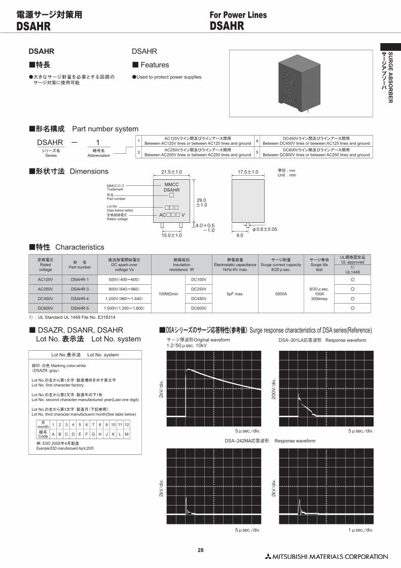
DSAHR
■特長
DSAHR
■ Features●�大きなサージ耐量を必要とする回路のサージ対策に使用可能
●�Used to protect power supplies.
■形名構成 Part number system
DSAHRシリーズ名
Series
− 1略号名
Abbreviation
1 AC125Vライン間及びラインアース間用Between AC125V lines or between AC125 lines and ground 4 DC450Vライン間及びラインアース間用
Between DC450V lines or between AC125 lines and ground
3 AC250Vライン間及びラインアース間用Between AC250V lines or between AC250 lines and ground 5 DC600Vライン間及びラインアース間用
Between DC600V lines or between AC250 lines and ground
■形状寸法 Dimensions 単位�: mmUnit : mm
Lot.No.(See below table)
21.5±1.0
φ0.8±0.05
17.5±1.0
15.0±1.0
4.0+0.5-1.0
29.0±1.0
9.0
MMCCDSAHR
AC V
MMCCロゴ
定格回路電圧
形名
Trademark
Rated voltage
Part number
■特性 Characteristics定格電圧
Ratedvoltage
形 名Part number
直流放電開始電圧DC spark-over
voltage Vs
絶縁抵抗Insulation
resistance lR
静電容量Electrostatic capacitance
1kHz-6V max.
サージ耐量Surge current capacity
8/20μsec.
サージ寿命Surge life
test
UL規格認定品UL approved
1)UL1449
AC125V DSAHR-1 500V(400〜600)
100MΩmin
DC100V
5pF max. 5000A8/20μsec.
100A300times
○
AC250V DSAHR-3 800V(640〜960) DC250V ○
DC450V DSAHR-4 1,200V(960〜1,440) DC450V ○
DC600V DSAHR-5 1,500V(1,200〜1,800) DC600V ○
1)�:�UL Standard UL 1449 File No. E318314
■ DSAZR, DSANR, DSAHR Lot No. 表示法 Lot No. system
Lot No.表示法 Lot No. system
捺印:白色 Marking color:white(DSAZR:gray)
Lot No.の左から第1文字:製造場所を示す英文字Lot No. first character:factory
Lot No.の左から第2文字:製造年の下1桁Lot No. second character:manufactured year(Last one digit)
Lot No.の左から第3文字:製造月(下記参照)Lot No. third character:manufactuerd month(See table below)
例:E5D 2005年4月製造Example:E5D manufactuerd April,2005
月month 1 2 3 4 5 6 7 8 9 10 11 12
略号Code A B C D E F G H J K L M
■DSAシリーズのサージ応答特性(参考値)Surge response characteristics of DSA series(Reference)サージ原波形1.2/50μsec. 10kV
5μsec./div.
2kV/
div.
200V
/div
.
5μsec./div.
5μsec./div.
2kV/
div.
2kV/
div.
1μsec./div.
DSA–301LA応答波形
DSA–242MA応答波形
Original waveform Response waveform
Response waveform
29
SUR
GE A
BSO
RB
ER
サージアブソーバ
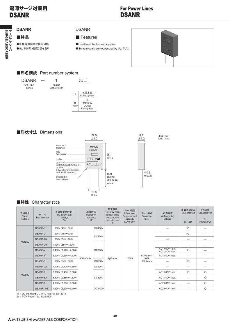
DSANR DSANRFor Power Lines電源サージ対策用
DSANR
■特長
DSANR
■ Features●�各種電源回路に使用可能
●�UL,�TÜV規格認定品もあり
●�Used to protect power supplies.●�Some models are recognized by UL, TÜV.
■形名構成 Part number system
DSANRシリーズ名
Series
− 1略号名
Abbreviation
(UL)
(UL) UL認定品UL Recognized
無None
UL非認定品UL not
Recognized
■形状寸法 Dimensions単位�: mmUnit : mm
22.5±1.0
28.1±1.0
φ0.8±0.05
8.7±1.0
15.0±1.0
15.0最小値
MMCCDSANR
AC V
MMCCロゴ
Lot.No.
定格回路電圧
形名
ULマークUL認定品のみ捺印されます。
Minimumvalue
Trademark
Rated voltage
Part number
UL markOnly parts marked with thismark are UL approved.
1) : UL Standard UL 1449 File No. E3183142) : TÜV Report No. J9251508
■特性 Characteristics
定格電圧Ratedvoltage
形 名Part number
直流放電開始電圧DC spark-over
voltageVs
絶縁抵抗Insulationresistance
lR
静電容量1kHz-6V max.Electrostaticcapacitance
1kHz-6V max.C
サージ耐量8/20μsec.
Surge currentcapacity
8/20μsec.
サージ寿命Surge life
test.
AC耐電圧Withstanding
voltage
UL規格認定品UL approved
EN認証EN approved
1)UL1449
2)EN62368-1
AC125V
DSANR-1 500V (400〜600)
100MΩmin.
DC100V
2pF max. 1000A8/20μsec.
100A500 times
― ○ ―
DSANR-2 600V (480〜720)DC250V
― ○ ―
DSANR-2A 800V (640〜960) ― ― ―
DSANR-2B 1,100V (880〜1,320)
DC500V
― ― ―
DSANR-4 2,400V (1,920〜2,880) AC1,000V-1min.AC1,200V-3sec. ○ ―
DSANR-6 3,600V (2,880〜4,320) AC1,800V-3sec. ― ―
AC250V
DSANR-3 800V (640〜960) DC250V ― ○ ―
DSANR-3A 1,400V (1,120〜1,680) DC500V ― ― ―
DSANR-5 3,000V (2,400〜3,600)
DC500V
AC1,500V-1min. ○ ○
DSANR-6A 3,600V (2,880〜4,320) AC1,800V-3sec. ― ○
DSANR-9 4,000V (3,200〜4,800) AC2,000V-1min. ― ○
DSANR-10B 4,500V (3,600〜5,400) DC1000V AC2,000V-1min. ― ○
30
SUR
GE A
BSO
RB
ER
サージアブソーバ
1 AC125V
2 AC250V
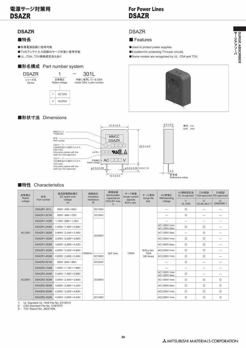
DSAZR DSAZRFor Power Lines電源サージ対策用
1) : UL Standard UL 1449 File No. E3183142) : CSA Standard File No. CA870703) : TÜV Report No. J9251508
■特性 Characteristics
定格電圧Ratedvoltage
形名Part number
直流放電開始電圧DC spark-over
voltageVs
絶縁抵抗Insulationresistance
lR
静電容量Electrostaticcapacitance
1kHz-6V max.C
サージ耐量Surge current
capacity8/20μsec.
サージ寿命Surge life
test.
AC耐電圧Withstanding
voltage
UL規格認定品UL recognized
CSA認証CSA approved
EN認証EN approved
1)UL1449
2)C22.2No.269.4-17
3)EN62368-1
AC125V
DSAZR1-301L 500V (400〜600)
100MΩmin.
DC100V
2pF max. 1000A8/20μsec.
100A300 times
― ○ ― ―
DSAZR1-501M 600V (480〜720) DC250V ― ○ ― ―
DSAZR1-102M 1,100V (880〜1,320)
DC500V
― ― ― ―
DSAZR1-242M 2,400V (1,920〜2,880) AC1,000V-1min.AC1,200V-3sec. ○ ○ ―
DSAZR1-282M 2,800V (2,240〜3,360) AC1,250V-3sec. ― ○ ―
DSAZR1-302M 3,000V (2,400〜3,600) AC1,500V-1min. ○ ○ ―
DSAZR1-362M 3,600V (2,880〜4,320) AC1,800V-3sec. ○ ○ ―
DSAZR1-402M 4,000V (3,200〜4,800) AC2,000V-1min. ○ ○ ―
DSAZR1-452M 4,500V (3,600〜5,400) DC1000V AC2,000V-1min. ○ ○ ―
AC250V
DSAZR2-501M 800V (640〜960) DC250V ― ○ ― ―
DSAZR2-102M 1,400V (1,120〜1,680)
DC500V
― ― ― ―
DSAZR2-242M 2,400V (1,920〜2,880) AC1,000V-1min.AC1,200V-3sec. ○ ― ―
DSAZR2-302M 3,000V (2,400〜3,600) AC1,500V-1min. ○ ○ ○
DSAZR2-362M 3,600V (2,880〜4,320) AC1,800V-3sec. ○ ○ ○
DSAZR2-402M 4,000V (3,200〜4,800) AC2,000V-1min. ○ ○ ○
DSAZR2-452M 4,500V (3,600〜5,400) DC1000V AC2,000V-1min. ○ ○ ○
DSAZR■特長
DSAZR■ Features
●�各種電源回路に使用可能
●�TVのアンテナ入力回路のサージ対策に使用可能
●�UL、CSA、TÜV規格認定品もあり
●�Used to protect power supplies.●�Excellent for protecting TV-tuner circuits.●�Some models are recognized by UL, CSA and TÜV.
■形名構成 Part number system
1定格電圧
Rated voltage
DSAZRシリーズ名
Series
301L内部に使用している DSA
Inside DSA ,s part number
−
■形状寸法 Dimensions単位�: mmUnit : mm
21.5±0.5
28.5±0.5
φ0.5±0.05
12.5±0.5
φ0.8±0.05 6.0±1.0
MMCCDSAZR
AC V
8.5±0.5
4.2参考値
MMCCロゴ
Lot.No.→
定格電圧→
形名
CSAマークCSA認定品のみ捺印されます。
TÜVマークTÜV認定品のみ捺印されます。
Reference value
Trademark
Rated voltage
Part number
CSA markOnly parts marked with thismark are CSA approved.
TÜV markOnly parts marked with thismark are TÜV approved.
®
31
SUR
GE A
BSO
RB
ER
サージアブソーバ
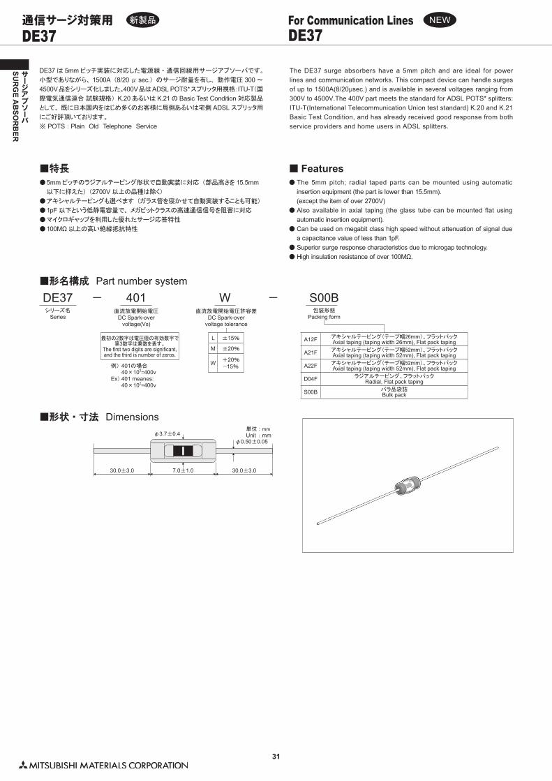
DE37 DE37For Communication Lines通信サージ対策用
DE37 は 5mm ピッチ実装に対応した電源線・通信回線用サージアブソーバです。
小型でありながら、 1500A (8/20 μ sec.) のサージ耐量を有し、 動作電圧 300 〜
4500V品をシリーズ化しました。400V品はADSL POTS*スプリッタ用視格:ITU-T(国際電気通信連合�試験規格) K.20 あるいは K.21 の Basic Test Condition 対応製品
として、 既に日本国内をはじめ多くのお客様に局側あるいは宅側 ADSL スプリッタ用
にご好評頂いております。
※�POTS :Plain Old Telephone Service
The DE37 surge absorbers have a 5mm pitch and are ideal for power lines and communication networks. This compact device can handle surges of up to 1500A(8/20μsec.) and is available in several voltages ranging from 300V to 4500V.The 400V part meets the standard for ADSL POTS* splitters: ITU-T(International Telecommunication Union test standard) K.20 and K.21Basic Test Condition, and has already received good response from both service providers and home users in ADSL splitters.
●��5mm ピッチのラジアルテーピング形状で自動実装に対応 (部品高さを 15.5mm
以下に抑えた) (2700V 以上の品種は除く)
●��アキシャルテーピングも選べます (ガラス管を寝かせて自動実装することも可能)
●��1pF 以下という低静電容量で、 メガビットクラスの高速通信信号を阻害に対応
●��マイクロギャップを利用した優れたサージ応答特性
●��100MΩ 以上の高い絶縁抵抗特性
■特長●��The 5mm pitch; radial taped parts can be mounted using automatic
insertion equipment (the part is lower than 15.5mm).� (except the item of over 2700V)●��Also available in axial taping (the glass tube can be mounted flat using
automatic insertion equipment).●��Can be used on megabit class high speed without attenuation of signal due
a capacitance value of less than 1pF.●��Superior surge response characteristics due to microgap technology.●��High insulation resistance of over 100MΩ.
■ Features
■形名構成 Part number system
DE37シリーズ名
Series
− 401直流放電開始電圧
DC Spark-overvoltage(Vs)
L ±15%
M ±20%
W +20%−15%
W直流放電開始電圧許容差
DC Spark-overvoltage tolerance
− S00B包装形態
Packing form
最初の2数字は電圧値の有効数字で第3数字は乗数を表す。
The first two digits are significant,and the third is number of zeros.
例)�401の場合� 40×102=400vEx) 401 meanes:� 40×102=400v
■形状・寸法 Dimensions単位�: mmUnit : mm
30.0±3.0 30.0±3.0
φ0.50±0.05φ3.7±0.4
7.0±1.0
新製品 NEW
A12F アキシャルテーピング(テープ幅26mm)、フラットパックAxial taping (taping width 26mm), Flat pack taping
A21F アキシャルテーピング(テープ幅52mm)、フラットパックAxial taping (taping width 52mm), Flat pack taping
A22F アキシャルテーピング(テープ幅52mm)、フラットパックAxial taping (taping width 52mm), Flat pack taping
D04F ラジアルテーピング、フラットパックRadial, Flat pack taping
S00B バラ品袋詰Bulk pack
32
SUR
GE A
BSO
RB
ER
サージアブソーバ
DE37 DE37For Communication Lines通信サージ対策用
1)�:�バリスタ (AC125V : V 1mA ≧ 270V D ≧φ 5mm) と電気的に直列接続する事により、 認定されます。� � Approved if used with a varistor�(125VAC�:�V1mA ≧ 270V,�φ≧ 5mm)�electrically connected in series.2)�:�バリスタ (AC125V : V�1mA ≧ 270V D ≧φ 5mm, AC250V : V 1mA ≧ 470V D ≧φ 5mm) と電気的に直列接続する事により、 認定されます。� � Approved if used with a varistor�(125VAC�:�V1mA ≧ 270V,�φ≧ 5mm�;�250VAC�:�V1mA ≧ 470V,�φ≧ 5mm) electrically connected in series.3)�:�バリスタ (V 1mA ≧ 470V D ≧φ 5mm) と電気的に直列接続する事により、 認定されます。� � Approved if used with a varistor�(V1mA ≧ 470V,�φ≧ 5mm) electrically connected in series.4)�:�UL Standard UL 497B File No. E175280 DC spark-over voltage is described as break down voltage in the UL report.5)�:�UL Standard UL 1449 File No. E3183146)�:�TÜV Report No.J50164439
■特性 Characteristics
形 名Part number
直流放電開始電圧DC spark-over
voltageVs
絶縁抵抗Insulationresistance
IR
静電容量Electrostaticcapacitance
1kHz-6V max.
サージ耐量Surge current
capacity8/20μsec.
サージ寿命Surge life
test
AC耐電圧Withstanding
Voltage
UL規格認定品UL recognized
EN規格認定品EN recognized
4)UL 497B
5)UL1449
6)EN62368-1
DE37-301L 300V (255〜345)
100MΩmin.
DC 100V
1pF max. 1500A
8/20μsec.100A 300times
― ○ ― ―
DE37-351M 350V (280〜420)
DC 250V
― ○ ― ―
DE37-401W 400V (340〜480) ― ○ ― ―
DE37-501M 500V (400〜600) ― ○ ― ―
DE37-102M 1,000V (800〜1,200)
DC 500V
― ― ― ―
DE37-272M 2,700V (2,160〜3,240)
8/20μsec.100A 200times
AC1,000V-1min.AC1,200V-3sec ― ○��1) ―
DE37-302M 3,000V (2,400〜3,600) AC1,500V-1min. ― ○��2) ○��3)
DE37-362M 3,600V (2,880〜4,320) AC1,800V-3sec ― ○��2) ○��3)
DE37-452M 4,500V (3,600〜5,400) DC 1000V AC2,000V-1min. ― ○��2) ○��3)
NEW
●�サ−ジ試験
� 10/700μsec 1.5kV/4kV(25Ω)±5回●�AC誘導試験
� AC600V(600Ω)1sec.�5回●�AC混触試験
� AC230V(10〜1000Ω)15min.� 但し、AC230V印加時にDE37-401Wは動作しません。
■ ITU-T K.20 Basic Test Condition について
●�Surge Test : 10/700μsec, 1.5kV/4kV (25Ω), 5 times.●�AC Induced Test : AC600V (600Ω), 1sec., 5 times.●�AC Cross Test : AC230V(10〜1000Ω), 15min.� (however, AC230 is too low for the DE37-401W to react)
■ Basic Conditions for ITU-T K.20
新製品 NEW
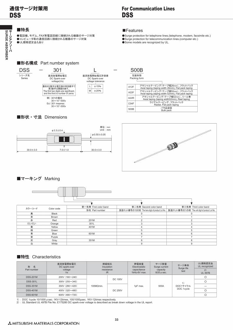
33
SUR
GE A
BSO
RB
ER
サージアブソーバ
DSS DSSFor Communication Lines通信サージ対策用
●�電話機、モデム、FAX等電話回線に接続される機器のサージ対策●�コンピュータ等の通信回路に接続される機器のサージ対策●�UL規格認定品もあり
■特長●�Surge protection for telephone lines.(telephone, modem, facsimile etc.)●�Surge protection for telecommunication lines.(computer etc.)●�Some models are recognized by UL.
■Features
■形名構成 Part number system
DSSシリーズ名
Series
− 301直流放電開始電圧
DC Spark-overvoltage(Vs)
A12F アキシャルテーピング(テープ幅26mm)、フラットパックAxial taping (taping width 26mm), Flat pack taping
A22F アキシャルテーピング(テープ幅52mm)、フラットパックAxial taping (taping width 52mm), Flat pack taping
A22R アキシャルテーピング(テープ幅52mm)、リール巻Axial taping (taping width52mm), Reel taping
C04F ラジアルテーピング、フラットパックRadial, Flat pack taping
S00B バラ品袋詰Bulk pack
L ±15%
M ±20%
L直流放電開始電圧許容差
DC Spark-overvoltage tolerance
− S00B包装形態
Packing form
最初の2数字は電圧値の有効数字で第3数字は乗数を表す。
The first two digits are significant,and the third is number of zeros.
例)�301の場合� 30×101=300vEx) 301 meanes:� 30×101=300v
■形状・寸法 Dimensions
単位�: mmUnit : mm
30.0±3.0 30.0±3.0
φ0.50±0.05
φ3.3±0.4
7.0±1.0
■マーキング Marking
カラーコード Color code第一色帯 First color band 第二色帯 Second color band 第三色帯 Third color band
形名 Part number 製造ロット番号の10の桁 The tens digit of product Lot No. 製造ロット番号の1の桁 The unit digit of product Lot No.黒 Black 0 0茶 Brown 1 1赤 Red 201M 2 2
だいだい Orange 301L 3 3黄 Yellow 401M 4 4緑 Green 5 5青 Blue 601M 6 6紫 Purple 7 7灰 Gray 351M 8 8白 White 9 9
1) : DOC 1cycle 10/1000μsec. 1KV-12times, 100/1000μsec. 1KV-12times respectively.2) : UL Standard UL 497B File No. E175280 DC spark-over voltage is described as break down voltage in the UL report.
■特性 Characteristics
形 名Part number
直流放電開始電圧DC spark-over
voltageVs
絶縁抵抗Insulationresistance
IR
静電容量Electrostaticcapacitance
1kHz-6V max.
サージ耐量Surge current
capacity8/20μsec.
サージ寿命Surge life
test
UL規格認定品UL recognized
2)UL 497B
DSS-201M 200V (160〜240)
100MΩmin.
DC 100V
1pF max. 500A1)
DOC1サイクルDOC 1cycle
○
DSS-301L 300V (255〜345) ○
DSS-351M 350V (280〜420)
DC 250V
―
DSS-401M 400V (320〜480) ○
DSS-601M 600V (480〜720) ○
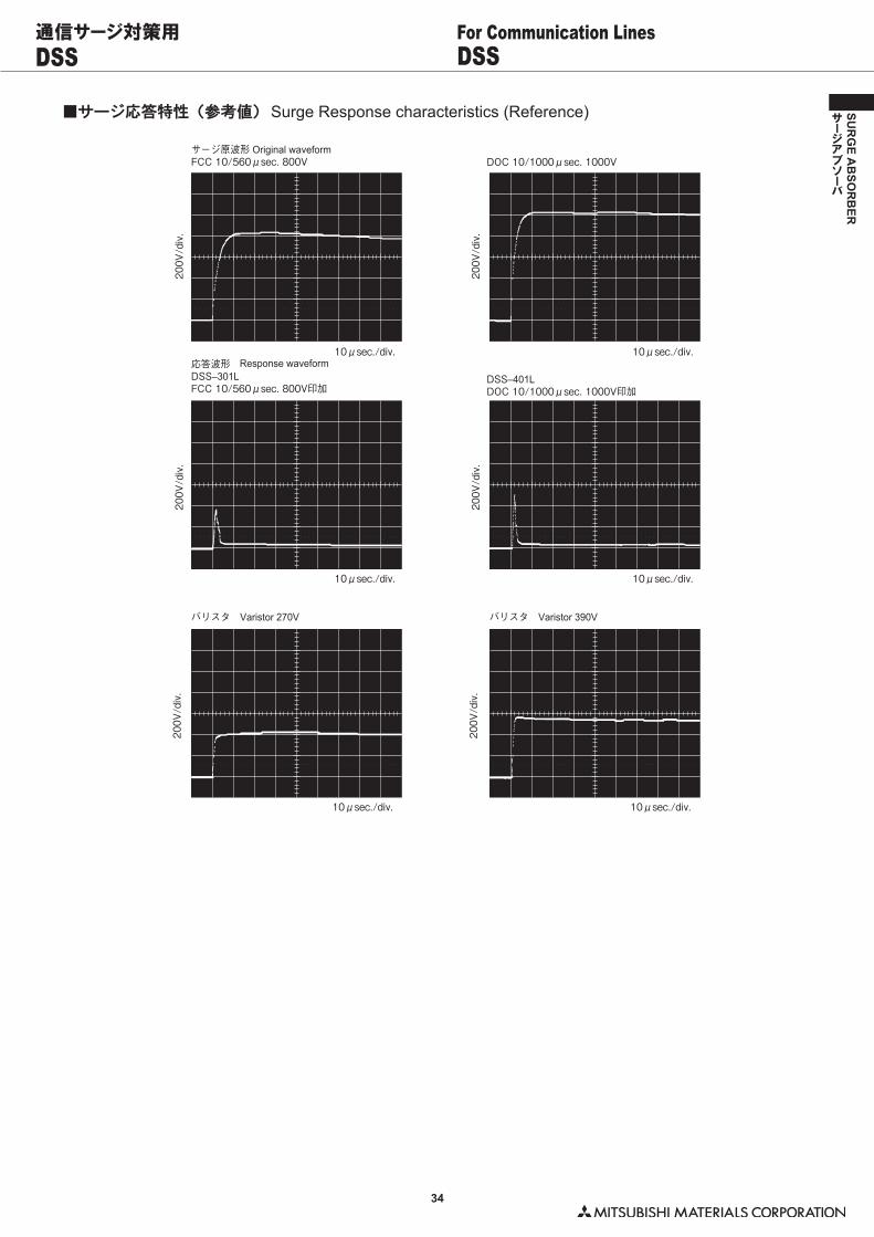
34
SUR
GE A
BSO
RB
ER
サージアブソーバ
DSS DSSFor Communication Lines通信サージ対策用
■サージ応答特性(参考値) Surge Response characteristics (Reference)
サージ原波形FCC 10/560μsec. 800V
10μsec./div.
200V
/div
.
200V
/div
.
10μsec./div.
10μsec./div.
200V
/div
.
200V
/div
.
10μsec./div.
DOC 10/1000μsec. 1000V
応答波形DSS–301LFCC 10/560μsec. 800V印加
DSS–401LDOC 10/1000μsec. 1000V印加
10μsec./div.
200V
/div
.
200V
/div
.
10μsec./div.
バリスタ Varistor 270V バリスタ Varistor 390V
Original waveform
Response waveform
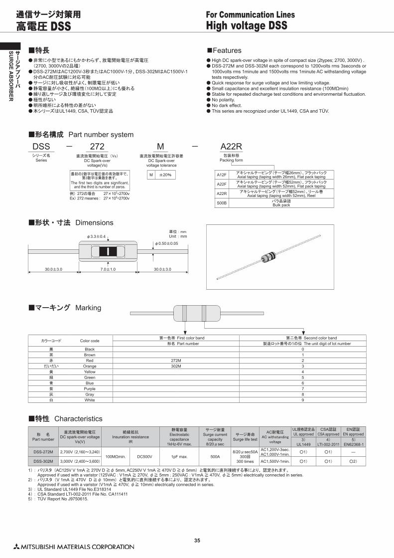
35
SUR
GE A
BSO
RB
ER
サージアブソーバ
高電圧 DSS High voltage DSSFor Communication Lines通信サージ対策用
●��非常に小型であるにもかかわらず、放電開始電圧が高電圧� (2700, 3000Vの2品種)●��DSS-272MはAC1200V-3秒またはAC1000V-1分、DSS-302MはAC1500V-1
分のAC耐圧試験に対応可能●��サージに対し吸収性がよく、制限電圧が低い●��静電容量が小さく、絶縁性(100MΩ以上)にも優れる●��繰り返しサージ及び環境変化に対して安定●��極性がない●��明所暗所による特性の差がない●��本シリーズはUL1449, CSA, TÜV認定品
■特長●��High DC spark-over voltage in spite of compact size (2types; 2700, 3000V) .●��DSS-272M and DSS-302M each correspond to 1200volts rms 3seconds or
1000volts rms 1minute and 1500volts rms 1minute AC withstanding voltage tests respectively.
●��Quick response for surge voltage and low limiting voltage.●��Small capacitance and excellent insulation resistance (100MΩmin)●��Stable for repeated discharge test conditions and environmental fluctuation.●��No polarity.●��No dark effect.●��This series are recognized under UL1449, CSA and TÜV.
■Features
■形名構成 Part number system
DSSシリーズ名
Series
− 272直流放電開始電圧 (Vs)
DC Spark-overvoltage(Vs)
A12F アキシャルテーピング(テープ幅26mm)、フラットパックAxial taping (taping width 26mm), Flat pack taping
A22F アキシャルテーピング(テープ幅52mm)、フラットパックAxial taping (taping width 52mm), Flat pack taping
A22R アキシャルテーピング(テープ幅52mm)、リール巻Axial taping (taping width 52mm), Reel
S00B バラ品袋詰Bulk pack
M ±20%
M直流放電開始電圧許容差
DC Spark-overvoltage tolerance
− A22R包装形態
Packing form
最初の2数字は電圧値の有効数字で、第3数字は乗数を表す。
The first two digits are significant, and the third is number of zeros.
例)�272の場合� 27×102=2700vEx) 272 meanes :� 27×102=2700v
■形状・寸法 Dimensions単位�: mmUnit : mm
30.0±3.0 30.0±3.0
φ0.50±0.05
φ3.3±0.4
7.0±1.0
■マーキング Marking
カラーコード Color code第一色帯 First color band 第二色帯 Second color band
形名 Part number 製造ロット番号の1の位 The unit digit of lot number黒 Black 0茶 Brown 1赤 Red 272M 2
だいだい Orange 302M 3黄 Yellow 4緑 Green 5青 Blue 6紫 Purple 7灰 Gray 8白 White 9
1)�:�バリスタ (AC125V V 1mA ≧ 270V D ≧φ 5mm, AC250V V 1mA ≧ 470V D ≧φ 5mm) と電気的に直列接続する事により、 認定されます。� � Approved if used with a varistor (125VAC�:�V1mA ≧ 270V, φ≧ 5mm�;�250VAC�:�V1mA ≧ 470V,�φ≧ 5mm)�electrically connected in series.2)�:�バリスタ (V 1mA ≧ 470V D ≧φ 10mm) と電気的に直列接続する事により、 認定されます。� � Approved if used with a varistor�(V1mA ≧ 470V,�φ≧ 10mm)�electrically connected in series.3)�:�UL Standard UL1449 File No.E3183144)�:�CSA Standard LTI-002-2011 File No. CA1114115)�:�TÜV Report No J9750615.
■特性 Characteristics
形 名Part number
直流放電開始電圧DC spark-over voltage
Vs(V)
絶縁抵抗Insuration resistance
IR
静電容量Electrostatic capacitance
1kHz-6V max.
サージ耐量Surge current
capacity8/20μsec
サージ寿命Surge life test
AC耐電圧AC�withstanding
voltage
UL規格認定品UL approved
CSA認証CSA approved
EN認証EN approved
3)UL1449
4)LTI-002-2011
5)EN62368-1
DSS-272M 2,700V (2,160〜3,240)100MΩmin. DC500V 1pF max. 500A
8/20μsec50A300回
300 times
AC1,200V-3sec.AC1,000V-1min. ○1) ○1) ―
DSS-302M 3,000V (2,400〜3,600) AC1,500V-1min. ○1) ○1) ○2)
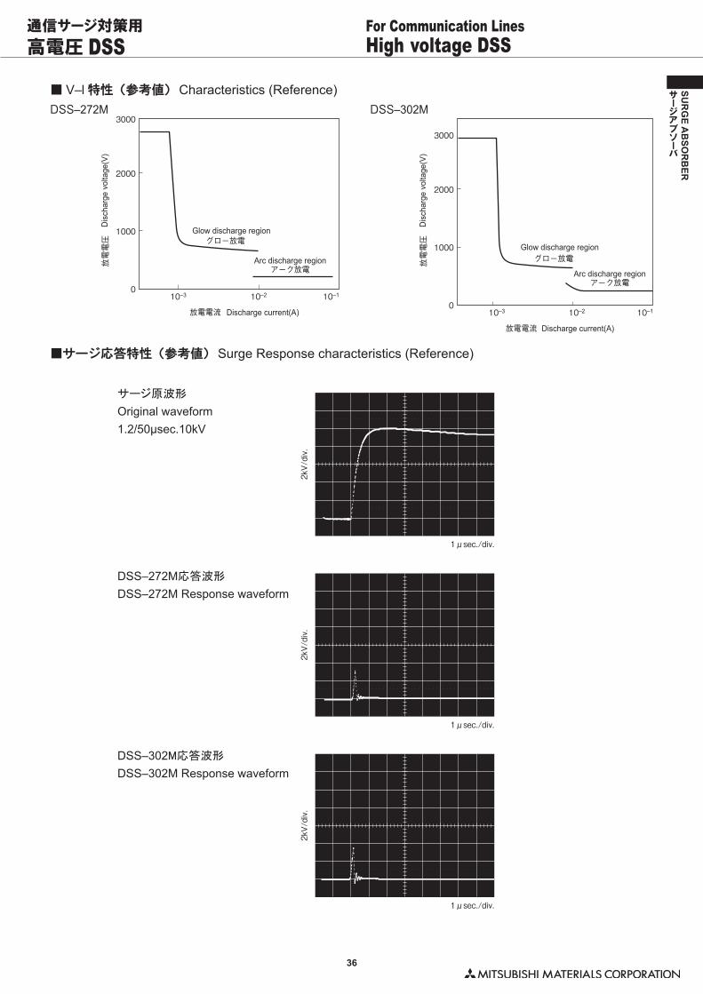
36
SUR
GE A
BSO
RB
ER
サージアブソーバ
高電圧 DSS High voltage DSSFor Communication Lines通信サージ対策用
■ V–l 特性(参考値) Characteristics (Reference)
3000DSS–272M
2000
1000
アーク放電
グロー放電
010–3 10–2 10–1
3000
DSS–302M
2000
1000
010–3 10–2 10–1
アーク放電
グロー放電放電電圧
Dis
char
ge v
olta
ge(V
)
放電電流 Discharge current(A)
Arc discharge region
Glow discharge region
放電電圧
Dis
char
ge v
olta
ge(V
)
放電電流 Discharge current(A)
Arc discharge region
Glow discharge region
■サージ応答特性(参考値) Surge Response characteristics (Reference)
サージ原波形
Original waveform1.2/50μsec.10kV
DSS–272M応答波形
DSS–272M Response waveform
DSS–302M応答波形
DSS–302M Response waveform
1μsec./div.
2kV/div.
2kV/div.
1μsec./div.
2kV/div.
1μsec./div.
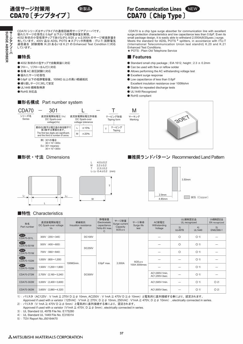
37
SUR
GE A
BSO
RB
ER
サージアブソーバ
■特性 Characteristics
■形状・寸法 Dimensions ■推奨ランドパターン Recommended Land PatternL 4.0±0.2 W 3.2±0.2T 2.3±0.2L1.L2 0.4±0.2 (mm)
4.85mm
2.9mm
3.50mm
銅箔(Copper)
T
W
L
L2L1
1)�:��バリスタ (AC125V : V 1mA ≧ 270V D ≧φ 10mm, AC250V : V 1mA ≧ 470V D ≧φ 10mm) と電気的に直列接続する事により、 認定されます。
� � Approved if used with a varistor�(125VAC�:�V1mA ≧ 270V, D ≧φ 10mm, 250VAC�:�V1mA ≧ 470V, D ≧φ 10mm) , electrically connected in series.2)�:�バリスタ (V 1mA ≧ 470V D ≧φ 5mm) と電気的に直列接続する事により、 認定されます。
� � Approved if used with a varistor (V1mA ≧ 470V, D ≧φ 5mm), electrically connected in series.3)�:�UL Standard UL 497B File No. E1752804)�:�UL Standard UL 1449 File No. E3183145)�:�TÜV Report No.J50164470
形名Part number
直流放電開始電圧DC Spark-over voltage
Vs
絶縁抵抗Insuation resistance
IR
静電容量Electrostatic capacitance
1kHz-6V max.C
サージ耐量Surge current
Capacity8/20μs
サージ寿命Surge life
test
AC耐電圧Withstanding
Voltage
UL規格認定品UL recognized
EN規格認定品EN�recognized
3)UL497B
4)UL1449
5)EN62368-1
CDA70-301L 300V (255〜345)
100MΩmin.
DC100V
0.6pF max. 2,000A 8/20μs100A 300times
― ○ ○�1) ―
CDA70-501M 500V (400〜600)DC250V
― ○ ○�1) ―
CDA70-701M 700V (560〜840) ― ○ ○�1) ―
CDA70-102M 1,000V (800〜1,200)
DC500V
― ― ○�1) ―
CDA70-152M 1,500V (1,200〜1,800) ― ― ○�1) ―
CDA70-272M 2,700V (2,160〜3,240) AC1,000V-1min.AC1,200V-3sec. ― ○�1) ―
CDA70-302M 3,000V (2,400〜3,600) AC1,500V-1min. ― ○�1) ○�2)
CDA70-362M 3,600V (2,880〜4,320) AC1,800V-3sec. ― ○�1) ○�2)
CDA70 〔チップタイプ〕 CDA70 〔Chip Type〕For Communication Lines通信サージ対策用
CDA70 シリーズはチップタイプの通信回線用サージアブソーバです。優れたサージ応答性と 0.6pF 以下という低静電容量を実現。4032 形状の小型低背チップでありながら 8/20 μ s-2,000A のサージ破壊耐量を有しています。 400V 品は ADSL POTS ★スプリッタ用規格�:� ITU-T( 国際電気通信連合 試験規格 )K.20 あるいは K.21 の Enhanced Test Condition に対応しています。
CDA70 is a chip type surge absorber for communication line with excellent surge protection characteristics and low capacitance less than 0.6pF. Even its small package design, it is easily able to withstand 2,000A(8/20μsec.) surge.Meets the standard for ADSL POTS ★ splitters, in accordance with ITU-T (International Telecommunication Union test standrd) K.20 and K.21 Enhanced Test Conditions.★ POTS : Plain Old Telephone Service
●��4032 形状の小型チップで自動実装に対応
●��フロー、 リフローはんだに対応
●��各種 AC 耐圧試験に対応
●��優れたサージ応答性
●��0.6pF 以下の低静電容量、 100MΩ 以上の高い絶縁抵抗
●��繰り返しサージに対して安定
●��UL1449 規格取得済
●��RoHS 対応品
■特長●��Standard small chip package ; EIA 1612, height ; 2.3 ± 0.2mm●��Can be used with flow or reflow solder●��Allows performing the AC withstanding voltage test●��Excellent surge response●��Low capacitance of less than 0.6pF� Excellent insulation resistance over 100Mohm●��Stable for repeated discharge tests ●��UL1449 Recognized●��RoHS compliant
■ Features
■形名構成 Part number system
CDA70シリーズ名
Series
−
L ±15%
M ±20%
L直流放電開始電圧許容差
DC Spark-overvoltage tolerance
−301直流放電開始電圧 (Vs)
DC Spark-overvoltage(Vs)
最初の2数字は電圧値の有効数字で第3数字は乗数を表す。
The first two digits are significant,and the third is number of zeros.
例)�301の場合� 30×101=300vEx) 301 meanes:� 30×101=300v
T テーピングTaping
Tテーピング形態
Taping form
MマーキングMarking
L 4.0±0.2 W 3.2±0.2T 2.3±0.2L1.L2 0.4±0.2 (mm)
4.85mm
2.9mm
3.50mm
銅箔(Copper)
T
W
L
L2L1
NEW
NEW
NEW
NEW
NEW
新製品 NEW
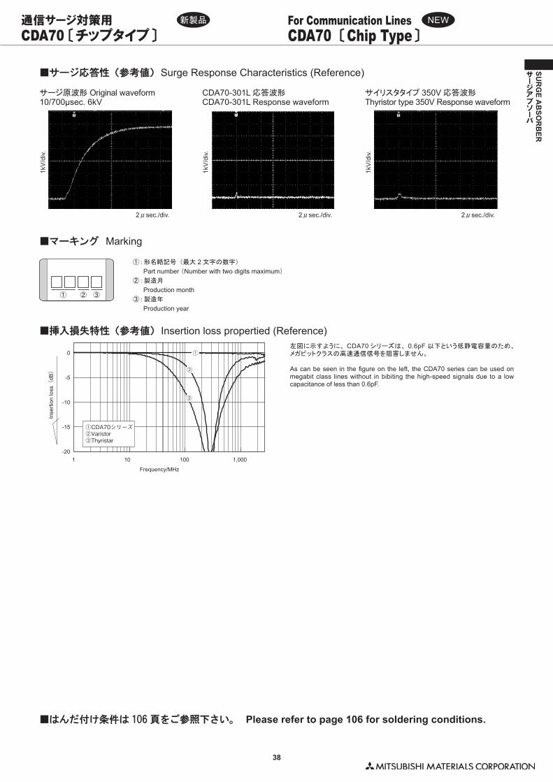
38
SUR
GE A
BSO
RB
ER
サージアブソーバ
■はんだ付け条件は 106 頁をご参照下さい。 Please refer to page 106 for soldering conditions.
■サージ応答性(参考値) Surge Response Characteristics (Reference)
左図に示すように、CDA70シリーズは、0.6pF以下という低静電容量のため、メガビットクラスの高速通信信号を阻害しません。
As can be seen in the figure on the left, the CDA70 series can be used on megabit class lines without in bibiting the high-speed signals due to a low capacitance of less than 0.6pF.
-20
-15
-10
-5
0
1 10 100 1,000
Frequency/MHz
Inse
rtion
loss(
dB)
①CDA70シリーズ②Varistor③Thyristar
①
②
③
■挿入損失特性(参考値) Insertion loss propertied (Reference)
サージ原波形 Original waveform10/700μsec. 6kV
サイリスタタイプ 350V 応答波形Thyristor type 350V Response waveform
CDA70-301L 応答波形CDA70-301L Response waveform
1kV
/div.
2μsec./div.1k
V/d
iv.2μsec./div.
1kV
/div.
2μsec./div.
■マーキング Marking
① : 形名略記号 (最大 2 文字の数字)
� Part number (Number with two digits maximum)
② : 製造月
� Production month③ : 製造年
� Production year
CDA70 〔チップタイプ〕 CDA70 〔Chip Type〕For Communication Lines通信サージ対策用 新製品 NEW
① ② ③
左図に示すように、 CDA70 シリーズは、 0.6pF 以下という低静電容量のため、メガビットクラスの高速通信信号を阻害しません。
As can be seen in the figure on the left, the CDA70 series can be used on megabit class lines without in bibiting the high-speed signals due to a low capacitance of less than 0.6pF.
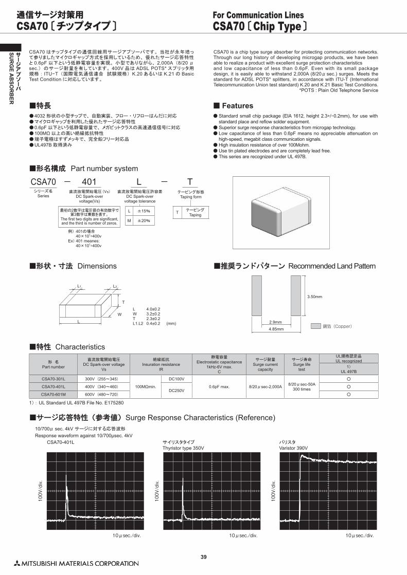
39
SUR
GE A
BSO
RB
ER
サージアブソーバ
CSA70 〔チップタイプ〕 CSA70 〔Chip Type〕For Communication Lines通信サージ対策用
CSA70 はチップタイプの通信回線用サージアブソーバです。 当社が永年培って参りましたマイクロギャップ方式を採用しているため、 優れたサージ応答特性と 0.6pF 以下という低静電容量を実現。 小型でありながら、 2,000A (8/20 μsec.) のサージ耐量を有しています。 400V 品は ADSL POTS* スプリッタ用規格 : ITU−T (国際電気通信連合 試験規格) K.20 あるいは K.21 の Basic Test Condition に対応しています。
CSA70 is a chip type surge absorber for protecting communication networks. Through our long history of developing microgap products, we have been able to realize a product with excellent surge protection characteristicsand low capacitance of less than 0.6pF. Even with its small package design, it is easily able to withstand 2,000A (8/20μsec.) surges. Meets the standard for ADSL POTS* splitters, in accordance with ITU-T (International Telecommunication Union test standard) K.20 and K.21 Basic Test Conditions. *POTS : Plain Old Telephone Service
●��4032 形状の小型チップで、 自動実装、 フロー ・ リフローはんだに対応●��マイクロギャップを利用した優れたサージ応答特性●��0.6pF 以下という低静電容量で、 メガビットクラスの高速通信信号に対応●��100MΩ 以上の高い絶縁抵抗特性●��端子電極はすずメッキで、 完全鉛フリー対応品●��UL497B 取得済み
■特長●��Standard small chip package (EIA 1612, height 2.3+/-0.2mm), for use with
standard place and reflow solder equipment.●��Superior surge response characteristics from microgap technology.●��Low capacitance of less than 0.6pF means no appreciable attenuation on
high-speed, megabit class communication signals.●��High insulation resistance of over 100Mohm.●��Use tin plated electrodes and are completely lead free.●��This series are recognized under UL 497B.
■ Features
CSA70シリーズ名
Series
−
L ±15%
M ±20%
L直流放電開始電圧許容差
DC Spark-overvoltage tolerance
−401直流放電開始電圧 (Vs)
DC Spark-overvoltage(Vs)
最初の2数字は電圧値の有効数字で第3数字は乗数を表す。
The first two digits are significant,and the third is number of zeros.
例)�401の場合� 40×101=400vEx) 401 meanes:� 40×101=400v
T テーピングTaping
Tテーピング形態
Taping form
■形名構成 Part number system
■形状・寸法 Dimensions ■推奨ランドパターン Recommended Land Pattern
L1
L
W
T
L2
L 4.0±0.2W 3.2±0.2T 2.3±0.2L1.L2 0.4±0.2 (mm)
4.85mm
2.9mm
3.50mm
銅箔(Copper)
■特性 Characteristics
1)�:��UL Standard UL 497B File No. E175280
形 名Part number
直流放電開始電圧DC Spark-over voltage
Vs
絶縁抵抗Insuration resistance
IR
静電容量Electrostatic capacitance
1kHz-6V max.C
サージ耐量Surge current
capacity
サージ寿命Surge life
test
UL規格認定品UL recognized
1)UL 497B
CSA70-301L 300V (255〜345)
100MΩmin.
DC100V
0.6pF max. 8/20μsec-2,000A 8/20μsec-50A300 times
○
CSA70-401L 400V (340〜460)DC250V
○
CSA70-601M 600V (480〜720) ○
■サージ応答特性(参考値) Surge Response Characteristics (Reference)10/700μ sec. 4kV サージに対する応答波形
Response waveform against 10/700μsec. 4kVCSA70-401L サイリスタタイプ
Thyristor type 350VバリスタVaristor 390V
100V/div.
10μsec./div.
100V/div.
10μsec./div.
100V/div.
10μsec./div.
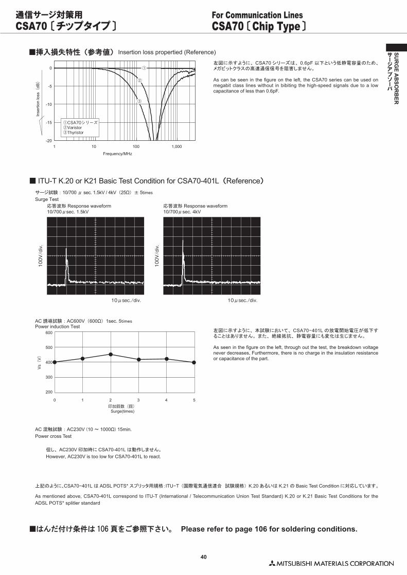
40
SUR
GE A
BSO
RB
ER
サージアブソーバ
■挿入損失特性(参考値) Insertion loss propertied (Reference)
左図に示すように、CSA70シリーズは、0.6pF以下という低静電容量のため、メガビットクラスの高速通信信号を阻害しません。
As can be seen in the figure on the left, the CSA70 series can be used on megabit class lines without in bibiting the high-speed signals due to a low capacitance of less than 0.6pF.
-20
-15
-10
-5
0
1 10 100 1,000
Frequency/MHz
Inse
rtion
loss(
dB)
①CSA70シリーズ②Varistor③Thyristor
①
②
③
CSA70 〔チップタイプ〕 CSA70 〔Chip Type〕For Communication Lines通信サージ対策用
左図に示すように、 CSA70 シリーズは、 0.6pF 以下という低静電容量のため、メガビットクラスの高速通信信号を阻害しません。
As can be seen in the figure on the left, the CSA70 series can be used on megabit class lines without in bibiting the high-speed signals due to a low capacitance of less than 0.6pF.
■ ITU-T K.20 or K21 Basic Test Condition for CSA70-401L(Reference)
サージ試験 : 10/700 μ sec. 1.5kV / 4kV (25Ω) ± 5timesSurge Test
応答波形 Response waveform10/700μsec. 1.5kV
応答波形 Response waveform10/700μsec. 4kV
100V/div.
10μsec./div.
100V/div.
10μsec./div.
左図に示すように、 本試験において、 CSA70−401L の放電開始電圧が低下することはありません。 また、 絶縁抵抗、 静電容量にも変化は生じません。
As seen in the figure on the left, through out the test, the breakdown voltage never decreases, Furthermore, there is no charge in the insulation resistance or capacitance of the part.
AC 誘導試験 : AC600V (600Ω) 1sec. 5timesPower induction Test
600
500
400
300
200
0 1 2 3 4 5印加回数(回)
Vs(V)
Surge(times)
AC 混触試験 : AC230V�(10 〜 1000Ω)�15min.Power cross Test
但し、 AC230V 印加時に CSA70-401L は動作しません。
However, AC230V is too low for CSA70-401L to react.
上記のように、CSA70−401L は ADSL POTS* スプリッタ用規格:ITU−T (国際電気通信連合 試験規格) K.20 あるいは K.21 の Basic Test Condition に対応しています。
As mentioned above, CSA70-401L correspond to ITU-T (International / Telecommunication Union Test Standard) K.20 or K.21 Basic Test Conditions for the ADSL POTS* splitler standard
■はんだ付け条件は 106 頁をご参照下さい。 Please refer to page 106 for soldering conditions.
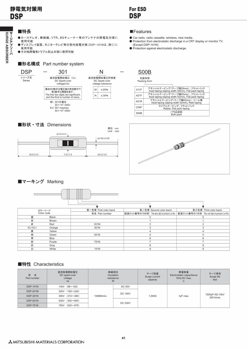
41
SUR
GE A
BSO
RB
ER
サージアブソーバ
DSP DSPFor ESD静電気対策用
●��カーステレオ、無線機、VTR、BSチューナー等のアンテナの静電気対策に使用可能
●��ディスプレイ装置、モニターテレビ等の管内放電対策(DSP-141Nは、除く)に使用可能
●��その他静電気トラブル防止対策に使用可能
■特長●��Car radio, radio cassette, wireless, new media.●��Protection from electrostatic discharge in a CRT display or monitor TV. (Except DSP-141N)●��Protection against electrostatic discharge.
■Features
DSPシリーズ名
Series
−
M ±20%
N ±30%
N直流放電開始電圧許容差
DC Spark-overvoltage tolerance
−301直流放電開始電圧 (Vs)
DC Spark-overvoltage(Vs)
最初の2数字は電圧値の有効数字で第3数字は乗数を表す。
The first two digits are significant,and the third is number of zeros.
例)�301の場合� 30×101=300vEx) 301 meanes:� 30×101=300v
S00B包装形態
Packing form
■形名構成 Part number system
A11F アキシャルテーピング(テープ幅26mm)、フラットパックAxial taping (taping width 26mm), Flat pack taping
A21F アキシャルテーピング(テープ幅52mm)、フラットパックAxial taping (taping width 52mm), Flat pack taping
A21R アキシャルテーピング(テープ幅52mm)、リール巻Axial taping (taping width 52mm), Reel taping
C04F ラジアルテーピング、フラットパックRadial, Flat pack taping
S00B バラ品袋詰Bulk pack
■形状・寸法 Dimensions単位�: mmUnit : mm
30.0±3.0 30.0±3.0
φ0.50±0.05
φ2.6±0.4
7.0±1.0
■マーキング Marking
カラーコードColor code
第一色帯 First color band 第二色帯 Second color band 第三色帯 Third color band形名 Part number 製造ロット番号の10の桁 The tens dijit of product Lot No. 製造ロット番号の1の桁 The unit dijit of product Lot No.
黒 Black 0 0茶 Brown 1 1赤 Red 201M 2 2
だいだい Orange 301N 3 3黄 Yellow 4 4緑 Green 501N 5 5青 Blue 6 6紫 Purple 751N 7 7灰 Gray 8 8白 White 141N 9 9
■特性 Characteristics
形 名Part number
直流放電開始電圧DC spark-over
voltageVs
絶縁抵抗Insulationresistance
IR
サージ耐量Surge current
capacity
静電容量Electrostatic capacitance
1kHz-6V max.C
サージ寿命Surge life
test
DSP-141N 140V (98〜182)
100MΩmin.
DC 50V
1,000A 1pF max. 1500pF-0Ω-10kV200 times
DSP-201M 200V (160〜240)DC 100V
DSP-301N 300V (210〜390)
DSP-501N 500V (350〜650)DC 250V
DSP-751N 750V (525〜975)
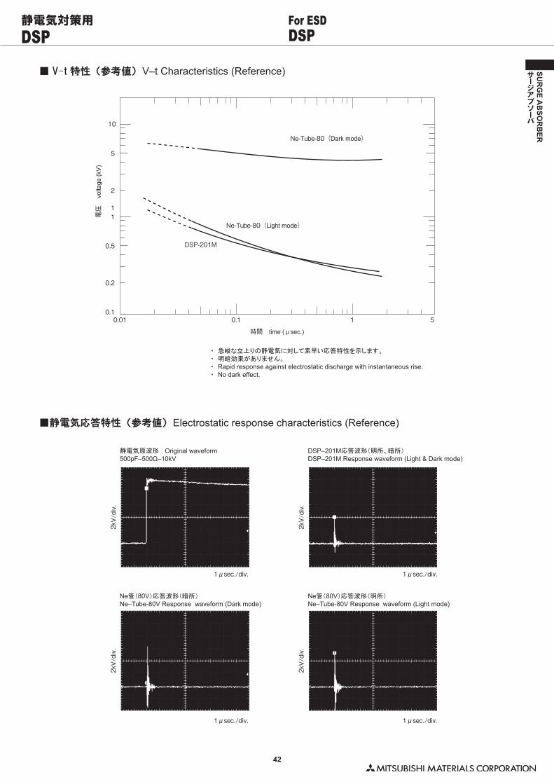
42
SUR
GE A
BSO
RB
ER
サージアブソーバ
DSP DSPFor ESD静電気対策用
■ V–t 特性(参考値) V–t Characteristics (Reference)
0.01 0.1
時間 time (μsec.)
Ne-Tube-80(Dark mode)
Ne-Tube-80(Light mode)
DSP-201M
1 5
電圧
0.1
0.2
0.5
11
2
5
10
volta
ge (k
V)
・� �急峻な立上りの静電気に対して素早い応答特性を示します。・� �明暗効果がありません。・� �Rapid response against electrostatic discharge with instantaneous rise.・ No dark effect.
■静電気応答特性(参考値) Electrostatic response characteristics (Reference)
1μsec./div.
2kV/div.
2kV/div.
1μsec./div.
1μsec./div.
2kV/div.
2kV/div.
1μsec./div.
静電気原波形���Original waveform500pF–500Ω–10kV
DSP–201M応答波形(明所、暗所)DSP–201M Response waveform (Light & Dark mode)
Ne管(80V)応答波形(暗所)Ne–Tube-80V Response waveform (Dark mode)
Ne管(80V)応答波形(明所)Ne–Tube-80V Response waveform (Light mode)
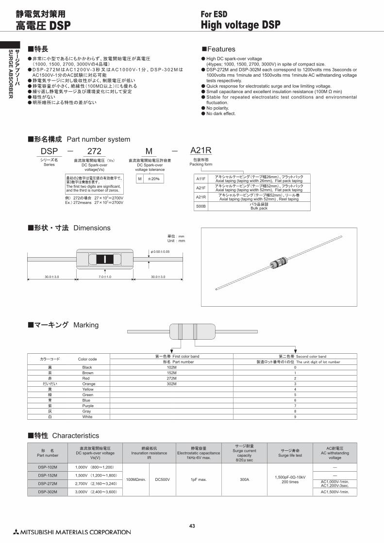
43
SUR
GE A
BSO
RB
ER
サージアブソーバ
高電圧 DSP High voltage DSPFor ESD静電気対策用
●��非常に小型であるにもかかわらず、放電開始電圧が高電圧� (1000, 1500, 2700, 3000Vの4品種)●��D S P - 2 7 2 MはA C 1 2 0 0 V- 3秒又はA C 1 0 0 0 V- 1分、D S P - 3 0 2 Mは
AC1500V-1分のAC試験に対応可能●��静電気サージに対し吸収性がよく、制限電圧が低い●��静電容量が小さく、絶縁性(100MΩ以上)にも優れる●��繰り返し静電気サージ及び環境変化に対して安定●��極性がない●��明所暗所による特性の差がない
■特長●��High DC spark-over voltage (4types; 1000, 1500, 2700, 3000V) in spite of compact size.●��DSP-272M and DSP-302M each correspond to 1200volts rms 3seconds or
1000volts rms 1minute and 1500volts rms 1minute AC withstanding voltage tests respectively.
●��Quick response for electrostatic surge and low limiting voltage.●��Small capacitance and excellent insulation resistance (100M Ω min)●��Stable for repeated electrostatic test conditions and environmental
fluctuation.●��No polarity.●��No dark effect.
■Features
DSPシリーズ名
Series
−
M ±20%
M直流放電開始電圧許容差
DC Spark-overvoltage tolerance
−272直流放電開始電圧 (Vs)
DC Spark-overvoltage(Vs)
最初の2数字は電圧値の有効数字で、第3数字は乗数を表す。The first two digits are significant, and the third is number of zeros.
例)� 272の場合� 27×102=2700VEx.)�272means� 27×102=2700V
A21R包装形態
Packing form
■形名構成 Part number system
A11F アキシャルテーピング(テープ幅26mm)、フラットパックAxial taping (taping width 26mm), Flat pack taping
A21F アキシャルテーピング(テープ幅52mm)、フラットパックAxial taping (taping width 52mm), Flat pack taping
A21R アキシャルテーピング(テープ幅52mm)、リール巻Axial taping (taping width 52mm) , Reel taping
S00B バラ品袋詰Bulk pack
■形状・寸法 Dimensions単位�: mmUnit : mm
30.0±3.0 30.0±3.0
φ0.50±0.05
7.0±1.0
■マーキング Marking
カラーコード Color code第一色帯 First color band 第二色帯 Second�color�band
形名 Part number 製造ロット番号の1の位 The�unit�digit�of�lot�number
黒 Black 102M 0
茶 Brown 152M 1
赤 Red 272M 2
だいだい Orange 302M 3
黄 Yellow 4
緑 Green 5
青 Blue 6
紫 Purple 7
灰 Gray 8
白 White 9
■特性 Characteristics
形 名Part number
直流放電開始電圧DC spark-over voltage
Vs(V)
絶縁抵抗Insuration resistance
IR
静電容量Electrostatic capacitance
1kHz-6V max.
サージ耐量Surge current
capacity8/20μsec
サージ寿命Surge life test
AC耐電圧AC withstanding
voltage
DSP-102M 1,000V (800〜1,200)
100MΩmin. DC500V 1pF max. 300A 1,500pF-0Ω-10kV200 times
―
DSP-152M 1,500V (1,200〜1,800) ―
DSP-272M 2,700V (2,160〜3,240) AC1,000V-1min.AC1,200V-3sec.
DSP-302M 3,000V (2,400〜3,600) AC1,500V-1min.
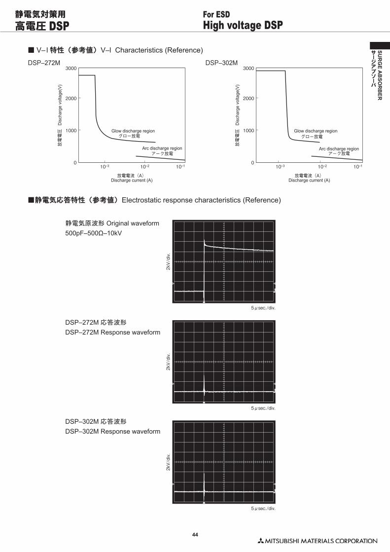
44
SUR
GE A
BSO
RB
ER
サージアブソーバ
高電圧 DSP High voltage DSPFor ESD静電気対策用
■ V– l 特性(参考値) V–l Characteristics (Reference)
3000DSP–272M
2000
1000
放電電圧
放電電流(A)
アーク放電
グロー放電
010–3 10–2 10–1
3000DSP–302M
2000
1000
放電電圧
放電電流(A)
010–3 10–2 10–1
アーク放電
グロー放電
Dis
char
ge v
olta
ge(V
)
Discharge current (A)
Arc discharge region
Glow discharge region
Dis
char
ge v
olta
ge(V
)
Discharge current (A)
Arc discharge region
Glow discharge region
■静電気応答特性(参考値) Electrostatic response characteristics (Reference)
静電気原波形 Original waveform500pF–500Ω–10kV
DSP–272M 応答波形
DSP–272M Response waveform
DSP–302M 応答波形
DSP–302M Response waveform
5μsec./div.
2kV/div.
2kV/div.
5μsec./div.
2kV/div.
5μsec./div.
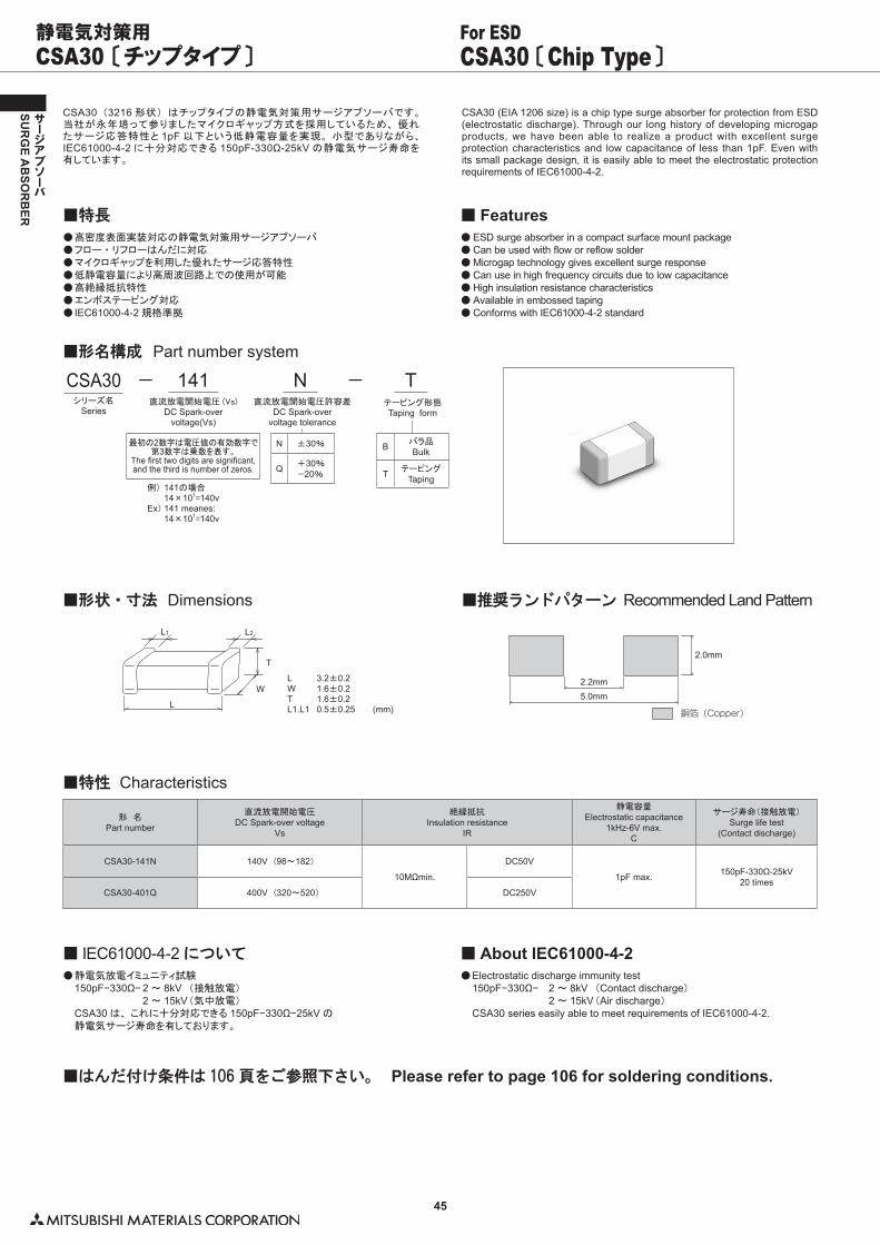
45
SUR
GE A
BSO
RB
ER
サージアブソーバ
CSA30 〔チップタイプ〕 CSA30 〔Chip Type〕For ESD静電気対策用
CSA30 (3216 形状) はチップタイプの静電気対策用サージアブソーバです。当社が永年培って参りましたマイクロギャップ方式を採用しているため、 優れたサージ応答特性と 1pF 以下という低静電容量を実現。 小型でありながら、IEC61000-4-2 に十分対応できる 150pF-330Ω-25kV の静電気サージ寿命を有しています。
CSA30 (EIA 1206 size) is a chip type surge absorber for protection from ESD (electrostatic discharge). Through our long history of developing microgap products, we have been able to realize a product with excellent surge protection characteristics and low capacitance of less than 1pF. Even with its small package design, it is easily able to meet the electrostatic protection requirements of IEC61000-4-2.
●��高密度表面実装対応の静電気対策用サージアブソーバ●��フロー ・ リフローはんだに対応●��マイクロギャップを利用した優れたサージ応答特性●��低静電容量により高周波回路上での使用が可能●��高絶縁抵抗特性●��エンボステーピング対応●��IEC61000-4-2 規格準拠
■特長●��ESD surge absorber in a compact surface mount package ●��Can be used with flow or reflow solder●��Microgap technology gives excellent surge response●��Can use in high frequency circuits due to low capacitance●��High insulation resistance characteristics●��Available in embossed taping●��Conforms with IEC61000-4-2 standard
■ Features
CSA30シリーズ名
Series
−
N ±30%
Q +30%−20%
N直流放電開始電圧許容差
DC Spark-overvoltage tolerance
−141直流放電開始電圧 (Vs)
DC Spark-overvoltage(Vs)
最初の2数字は電圧値の有効数字で第3数字は乗数を表す。
The first two digits are significant,and the third is number of zeros.
例)�141の場合� 14×101=140vEx) 141 meanes:� 14×101=140v
■形名構成 Part number system
B バラ品Bulk
T テーピングTaping
Tテーピング形態Taping form
■形状・寸法 Dimensions ■推奨ランドパターン Recommended Land Pattern
L 3.2±0.2W 1.6±0.2T 1.6±0.2L1.L1 0.5±0.25 (mm)
L1
L
W
T
L2
2.2mm5.0mm
2.0mm
銅箔(Copper)
■特性 Characteristics
形 名Part number
直流放電開始電圧DC Spark-over voltage
Vs
絶縁抵抗Insulation resistance
IR
静電容量Electrostatic capacitance
1kHz-6V max.C
サージ寿命(接触放電)Surge life test
(Contact discharge)
CSA30-141N 140V (98〜182)
10MΩmin.
DC50V
1pF max. 150pF-330Ω-25kV20 times
CSA30-401Q 400V (320〜520) DC250V
■はんだ付け条件は 106 頁をご参照下さい。 Please refer to page 106 for soldering conditions.
●��静電気放電イミュニティ試験� 150pF−330Ω− 2 〜 8kV� (接触放電)� � 2 〜 15kV�(気中放電)� CSA30 は、 これに十分対応できる 150pF−330Ω−25kV の� 静電気サージ寿命を有しております。
■ IEC61000-4-2 について●��Electrostatic discharge immunity test 150pF−330Ω− 2 〜 8kV (Contact discharge) 2 〜 15kV (Air discharge) CSA30 series easily able to meet requirements of IEC61000-4-2.
■ About IEC61000-4-2
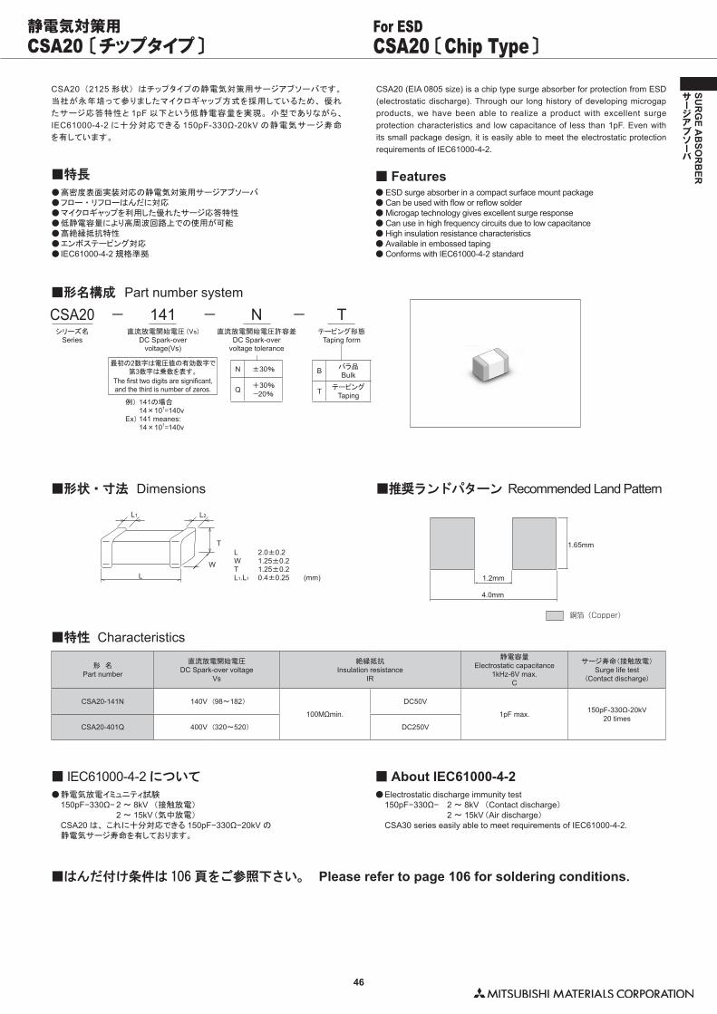
46
SUR
GE A
BSO
RB
ER
サージアブソーバ
N ±30%
Q +30%−20%
CSA20 〔チップタイプ〕 CSA20 〔Chip Type〕For ESD静電気対策用
■形状・寸法 Dimensions ■推奨ランドパターン Recommended Land Pattern
L 2.0±0.2W 1.25±0.2T 1.25±0.2L1.L1 0.4±0.25 (mm)
■特性 Characteristics
形 名Part number
直流放電開始電圧DC Spark-over voltage
Vs
絶縁抵抗Insulation resistance
IR
静電容量Electrostatic capacitance
1kHz-6V max.C
サージ寿命(接触放電)Surge life test
(Contact discharge)
CSA20-141N 140V (98〜182)
100MΩmin.
DC50V
1pF max. 150pF-330Ω-20kV20 times
CSA20-401Q 400V (320〜520) DC250V
■はんだ付け条件は 106 頁をご参照下さい。 Please refer to page 106 for soldering conditions.
●��静電気放電イミュニティ試験� 150pF−330Ω− 2 〜 8kV� (接触放電)� � 2 〜 15kV�(気中放電)� CSA20 は、 これに十分対応できる 150pF−330Ω−20kV の� 静電気サージ寿命を有しております。
■ IEC61000-4-2 について●��Electrostatic discharge immunity test 150pF−330Ω− 2 〜 8kV (Contact discharge) 2 〜 15kV (Air discharge) CSA30 series easily able to meet requirements of IEC61000-4-2.
■ About IEC61000-4-2
CSA20 (2125 形状) はチップタイプの静電気対策用サージアブソーバです。
当社が永年培って参りましたマイクロギャップ方式を採用しているため、 優れ
たサージ応答特性と 1pF 以下という低静電容量を実現。 小型でありながら、
IEC61000-4-2 に十分対応できる 150pF-330Ω-20kV の静電気サージ寿命
を有しています。
●��高密度表面実装対応の静電気対策用サージアブソーバ●��フロー ・ リフローはんだに対応●��マイクロギャップを利用した優れたサージ応答特性●��低静電容量により高周波回路上での使用が可能●��高絶縁抵抗特性●��エンボステーピング対応●��IEC61000-4-2 規格準拠
■特長
CSA20 (EIA 0805 size) is a chip type surge absorber for protection from ESD (electrostatic discharge). Through our long history of developing microgap products, we have been able to realize a product with excellent surge protection characteristics and low capacitance of less than 1pF. Even with its small package design, it is easily able to meet the electrostatic protection requirements of IEC61000-4-2.
●��ESD surge absorber in a compact surface mount package ●��Can be used with flow or reflow solder●��Microgap technology gives excellent surge response●��Can use in high frequency circuits due to low capacitance●��High insulation resistance characteristics●��Available in embossed taping●��Conforms with IEC61000-4-2 standard
■ Features
■形名構成 Part number system
141直流放電開始電圧 (Vs)
DC Spark-overvoltage(Vs)
CSA20シリーズ名
Series
N直流放電開始電圧許容差
DC Spark-overvoltage tolerance
− − −
最初の2数字は電圧値の有効数字で第3数字は乗数を表す。
The first two digits are significant,and the third is number of zeros.
例)�141の場合� 14×101=140vEx) 141 meanes:� 14×101=140v
B バラ品Bulk
T テーピングTaping
Tテーピング形態
Taping form
L1
LW
T
L2
4.0mm
1.2mm
1.65mm
銅箔(Copper)
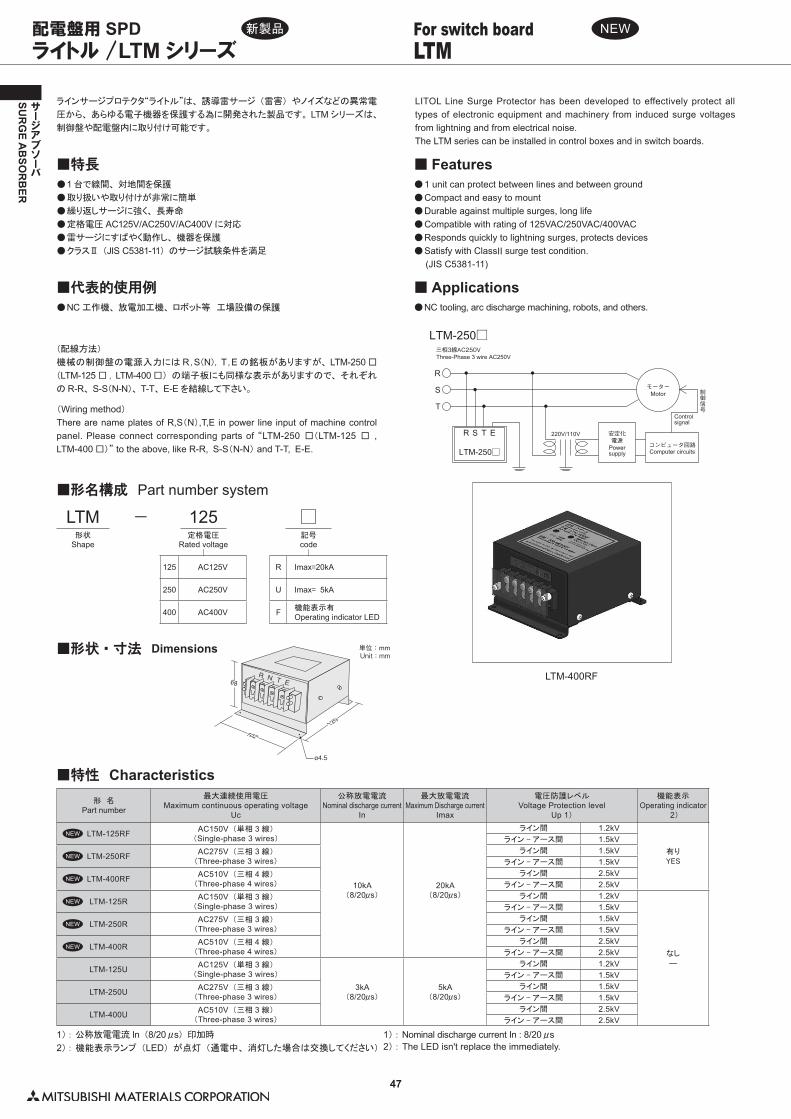
47
SUR
GE A
BSO
RB
ER
サージアブソーバ
ラインサージプロテクタ“ライトル”は、 誘導雷サージ (雷害) やノイズなどの異常電
圧から、 あらゆる電子機器を保護する為に開発された製品です。 LTM シリーズは、
制御盤や配電盤内に取り付け可能です。
LITOL Line Surge Protector has been developed to effectively protect all types of electronic equipment and machinery from induced surge voltages from lightning and from electrical noise. The LTM series can be installed in control boxes and in switch boards.
●��1 台で線間、 対地間を保護
●��取り扱いや取り付けが非常に簡単
●��繰り返しサージに強く、 長寿命
●��定格電圧 AC125V/AC250V/AC400V に対応
●��雷サージにすばやく動作し、 機器を保護
●��クラスⅡ (JIS C5381-11) のサージ試験条件を満足
●��1 unit can protect between lines and between ground●��Compact and easy to mount●��Durable against multiple surges, long life●��Compatible with rating of 125VAC/250VAC/400VAC●��Responds quickly to lightning surges, protects devices●��Satisfy with ClassII surge test condition. (JIS C5381-11)
(配線方法)
機械の制御盤の電源入力には R ,�S(N), T ,�E の銘板がありますが、 LTM-250 □
(LTM-125 □ , LTM-400 □) の端子板にも同様な表示がありますので、 それぞれ
の R-R、 S-S(N-N)、 T-T、 E-E を結線して下さい。
(Wiring method)There are name plates of R,S(N),T,E in power line input of machine control panel. Please connect corresponding parts of “LTM-250 □(LTM-125 □ , LTM-400 □)” to the above, like R-R, S-S(N-N) and T-T, E-E.
●��NC 工作機、 放電加工機、 ロボット等 工場設備の保護
■代表的使用例●��NC tooling, arc discharge machining, robots, and others.
■ Applications
LTM-250□
LTM-250□
R
T
S
R
安定化電源
制御信号
三相3線AC250V
コンピュータ回路
220V/110V
モーター
S T E
Powersupply
Three-Phase 3 wire AC250V
Computer circuits
Controlsignal
Motor
■形状・寸法 Dimensions
120
102
68
単位:mmUnit:mm
R N T E
ø4.5
ライトル /LTM シリーズ LTMFor switch board 配電盤用 SPD
LTM-400RF
■特性 Characteristics形 名
Part number
最大連続使用電圧Maximum continuous operating voltage
Uc
公称放電電流Nominal discharge current
In
最大放電電流Maximum Discharge current
Imax
電圧防護レベルVoltage Protection level
Up 1)
機能表示Operating indicator
�2)
LTM-125RF AC150V (単相 3 線)(Single-phase 3 wires)
10kA(8/20μs)
20kA(8/20μs)
ライン間 1.2kV
有りYES
ライン - アース間 1.5kV
LTM-250RF AC275V (三相 3 線)(Three-phase 3 wires)
ライン間 1.5kVライン - アース間 1.5kV
LTM-400RF AC510V (三相 4 線)(Three-phase 4 wires)
ライン間 2.5kVライン - アース間 2.5kV
LTM-125R AC150V (単相 3 線)(Single-phase 3 wires)
ライン間 1.2kV
なし―
ライン - アース間 1.5kV
LTM-250R AC275V (三相 3 線)(Three-phase 3 wires)
ライン間 1.5kVライン - アース間 1.5kV
LTM-400R AC510V (三相 4 線)(Three-phase 4 wires)
ライン間 2.5kVライン - アース間 2.5kV
LTM-125U AC125V (単相 3 線)(Single-phase 3 wires)
3kA(8/20μs)
5kA(8/20μs)
ライン間 1.2kVライン - アース間 1.5kV
LTM-250U AC275V (三相 3 線)(Three-phase 3 wires)
ライン間 1.5kVライン - アース間 1.5kV
LTM-400U AC510V (三相 3 線)(Three-phase 3 wires)
ライン間 2.5kVライン - アース間 2.5kV
■特長 ■ Features
1)�:��公称放電電流 In (8/20μs) 印加時
2)�:��機能表示ランプ (LED) が点灯 (通電中、 消灯した場合は交換してください)
1)�:��Nominal discharge current In : 8/20μs2) : The LED isn't replace the immediately.
LTM形状
Shape
125 AC125V
250 AC250V
400 AC400V
125定格電圧
Rated voltage
■形名構成 Part number system
−
R Imax=20kA
U Imax= 5kA
F 機能表示有Operating indicator LED
記号code
新製品 NEW
NEW
NEW
NEW
NEW
NEW
NEW

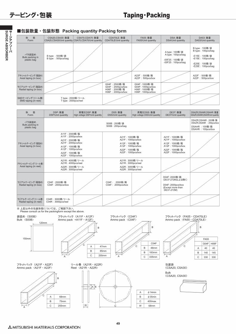
49
SUR
GE A
BSO
RB
ER
サージアブソーバ
テーピング・包装 Taping・Packing
■包装数量・包装形態 Packing quantity·Packing form形 態
FormCSA20,CSA30:数量
CSA20,CSA30/Unit quantityCSA70,CDA70:数量
CSA70,CDA70/Unit quantityCDA70LE:数量
CDA70LE/Unit quantityFA55:数量
FA55/Unit quantityDSA:数量
DSA/Unit quantityDA53:数量
DA53/Unit quantity
バラ袋詰めBulk packing in
plastic bagB type : 500個/袋B type : 500pcs/bag
A type : 100個/袋 A type : 100pcs/bag
-05F25 : 100個/袋-05F25 : 100pcs/bag
B type : 100個/袋B type : 100pcs/bag
-E15E : 100個/袋-E15E : 100pcs/bag
-E25E : 100個/袋-E25E : 100pcs/bag
アキシャルテーピング(箱詰め)Axial taping (in box)
A22F : 500個/箱A22F : 500pcs/box
A22F : 500個/箱A22F : 500pcs/box
ラジアルテーピング(箱詰め)Radial taping (in box)
G04F : 2500個/箱G04F : 2500pcs/boxH06F : 2000個/箱H06F : 2000pcs/box
G04F : 1000個/箱G04F : 1000pcs/boxH06F : 1000個/箱H06F : 1000pcs/box
SMDテーピング(リール巻)SMD taping (in reel)
T type : 2000個/リールT type : 2000pcs/reel
形 態Form
DSP:数量DSP/Unit quantity
高電圧DSP:数量High voltage DSP/Unit quantity
DSS:数量DSS/Unit quantity
高電圧DSS:数量High voltage DSS/Unit quantity
DE37:数量DE37/Unit quantity
DSAZR,DSANR,DSAHR:数量DSAZR,DSANR,DSAHR/Unit quantity
バラ袋詰めBulk packing in
plastic bagS00B : 200個/袋S00B : 200pcs/bag
DSAZR,DSANR : 200個/箱DSAZR,DSANR : 200pcs/boxDSAHR : 100個/箱DSAHR : 100pcs/box
アキシャルテーピング(箱詰め)Axial taping (in box)
A11F : 2000個/箱A11F : 2000pcs/boxA21F : 2000個/箱A21F : 2000pcs/boxA12F : 1000個/箱A12F : 1000pcs/boxA22F : 1000個/箱A22F : 1000pcs/box
A21F : 1000個/箱A21F : 1000pcs/boxA12F : 1000個/箱A12F : 1000pcs/boxA22F : 1000個/箱A22F : 1000pcs/box
A21F : 1000個/箱A21F : 1000pcs/boxA12F : 1000個/箱A12F : 1000pcs/boxA22F : 1000個/箱A22F : 1000pcs/box
アキシャルテーピング(リール巻)Axial taping (in reel)
A21R : 4000個/リールA21R : 4000pcs/reelA22R : 3000個/リールA22R : 3000pcs/reel
A21R : 3000個/リールA21R : 3000pcs/reelA22R : 3000個/リールA22R : 3000pcs/reel
ラジアルテーピング(箱詰め)Radial taping (in box)
C04F : 2000個/箱C04F : 2000pcs/box
C04F : 2000個/箱C04F : 2000pcs/box
D04F:2000個/箱(DE37-272M以上は除く)
D04F:2000pcs/box(Except more than DE37-272M)
ラジアルテーピング(リール巻)Radial taping (in reel)
C04R : 3000個/リールC04R : 3000pcs/reel
※��上記以外の包装形態については、 ご相談下さい。 Please consult us for the packingform except the above.
120mm
150mm
A
C
B
A
C
B
A
C
B
A
C
B
CW
BA
袋詰め 〈S00B〉Bulk <S00B>
フラットパック 〈A11F ・ A12F〉Ammo pack <A11F ・ A12F>
フラットパック 〈C04F〉Ammo pack <C04F>
フラットパック 〈FA55 ・ CDA70LE〉Ammo pack <FA55 ・ CDA70LE>
フラットパック 〈A21F ・ A22F〉Ammo pack <A21F ・ A22F>
リール巻 〈A21R ・ A22R〉Reel <A21R ・ A22R>
包装袋〈CSA20, CSA30〉
Bulk〈CSA20, CSA30〉
A 47mm
B 85mm
C 255mm
C04F
B 48mm
B 183mm
C 335mm
FA55
G04F H06F
A 40 40
B 140 145
C 330 330
A 68mm
B 75mm
C 255mm
A φ14min
B φ35min
C 400max
W 68mm
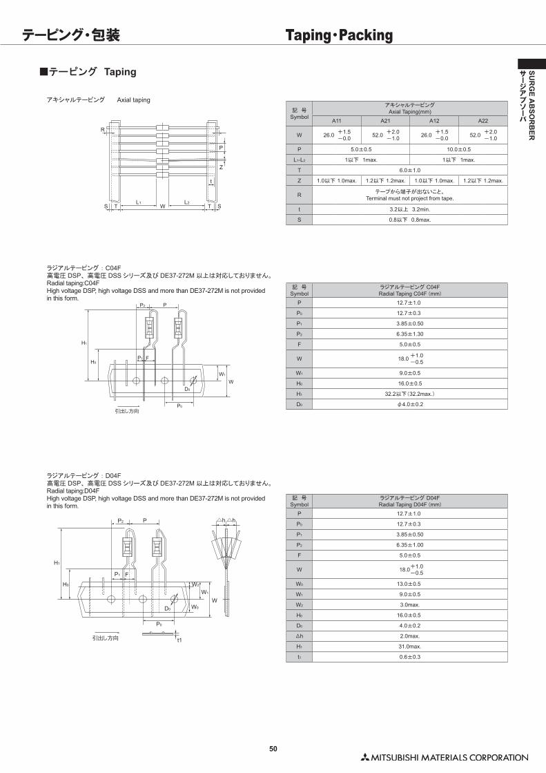
50
SUR
GE A
BSO
RB
ER
サージアブソーバ
テーピング・包装 Taping・Packing
■テーピング Taping
アキシャルテーピング� Axial taping
ラジアルテーピング : C04F高電圧 DSP、 高電圧 DSS シリーズ及び DE37-272M 以上は対応しておりません。Radial taping:C04FHigh voltage DSP, high voltage DSS and more than DE37-272M is not provided in this form.
ラジアルテーピング : D04F高電圧 DSP、 高電圧 DSS シリーズ及び DE37-272M 以上は対応しておりません。Radial taping:D04FHigh voltage DSP, high voltage DSS and more than DE37-272M is not provided in this form.
R
S T STWL1 L2
t
Z
P
引出し方向
W1
P0
D0
H1
H0
P2 P
P1 F
W
t1引出し方向
W1
W2
W0
P0
D0
H1
H0
P2 P
P1 F
△h△h
W
記 号Symbol
アキシャルテーピングAxial Taping(mm)
A11 A21 A12 A22
W 26.0 +1.5-0.0 52.0 +2.0
-1.0 26.0 +1.5-0.0 52.0 +2.0
-1.0
P 5.0±0.5 10.0±0.5
L1-L2 1以下 1max. 1以下 1max.
T 6.0±1.0
Z 1.0以下�1.0max. 1.2以下�1.2max. 1.0以下�1.0max. 1.2以下�1.2max.
R テープから端子が出ないこと。Terminal must not project from tape.
t 3.2以上 3.2min.
S 0.8以下 0.8max.
記 号Symbol
ラジアルテーピング�C04FRadial Taping C04F�(mm)
P 12.7±1.0
P0 12.7±0.3
P1 3.85±0.50
P2 6.35±1.30
F 5.0±0.5
W 18.0 +1.0-0.5
W1 9.0±0.5
H0 16.0±0.5
H1 32.2以下(32.2max.)
D0 φ4.0±0.2
記 号Symbol
ラジアルテーピング�D04FRadial Taping D04F�(mm)
P 12.7±1.0
P0 12.7±0.3
P1 3.85±0.50
P2 6.35±1.00
F 5.0±0.5
W 18.0+1.0-0.5
W0 13.0±0.5
W1 9.0±0.5
W2 3.0max.
H0 16.0±0.5
D0 4.0±0.2
△h 2.0max.
H1 31.0max.
t1 0.6±0.3
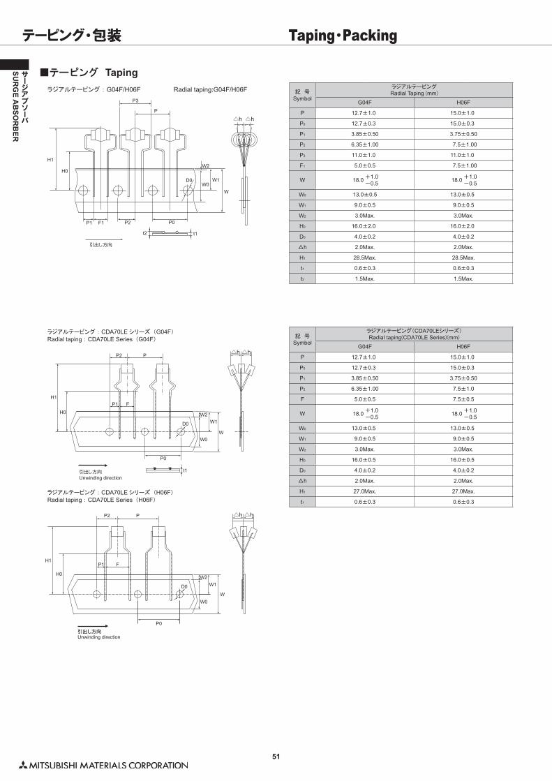
51
SUR
GE A
BSO
RB
ER
サージアブソーバ
Unwinding direction
t1
P0
WW0
W2W1D0
P2 P
P1 FH0
H1
引出し方向
△h △h
ラジアルテーピング : CDA70LE シリーズ (G04F)Radial taping : CDA70LE Series (G04F)
W
W0
W2W1
P0引出し方向
H1
H0
P2 P
D0
P1 F
△h △h
Unwinding direction
ラジアルテーピング : CDA70LE シリーズ (H06F)Radial taping : CDA70LE Series (H06F)
テーピング・包装 Taping・Packing
記 号Symbol
ラジアルテーピングRadial Taping (mm)
G04F H06F
P 12.7±1.0 15.0±1.0
P0 12.7±0.3 15.0±0.3
P1 3.85±0.50 3.75±0.50
P2 6.35±1.00 7.5±1.00
P3 11.0±1.0 11.0±1.0
F1 5.0±0.5 7.5±1.00
W 18.0 +1.0-0.5 18.0 +1.0
-0.5
W0 13.0±0.5 13.0±0.5
W1 9.0±0.5 9.0±0.5
W2 3.0Max. 3.0Max.
H0 16.0±2.0 16.0±2.0
D0 4.0±0.2 4.0±0.2
△h 2.0Max. 2.0Max.
H1 28.5Max. 28.5Max.
t1 0.6±0.3 0.6±0.3
t2 1.5Max. 1.5Max.
■テーピング Tapingラジアルテーピング : G04F/H06F� Radial taping:G04F/H06F
引出し方向
D0
P1
H0
H1
P
△h△h
t1t2
P0F1 P2
W0
W2
W1
W
P3
記 号Symbol
ラジアルテーピング(CDA70LEシリーズ)Radial taping(CDA70LE Series)(mm)
G04F H06F
P 12.7±1.0 15.0±1.0
P0 12.7±0.3 15.0±0.3
P1 3.85±0.50 3.75±0.50
P2 6.35±1.00 7.5±1.0
F 5.0±0.5 7.5±0.5
W 18.0 +1.0-0.5 18.0 +1.0
-0.5
W0 13.0±0.5 13.0±0.5
W1 9.0±0.5 9.0±0.5
W2 3.0Max. 3.0Max.
H0 16.0±0.5 16.0±0.5
D0 4.0±0.2 4.0±0.2
△h 2.0Max. 2.0Max.
H1 27.0Max. 27.0Max.
t1 0.6±0.3 0.6±0.3
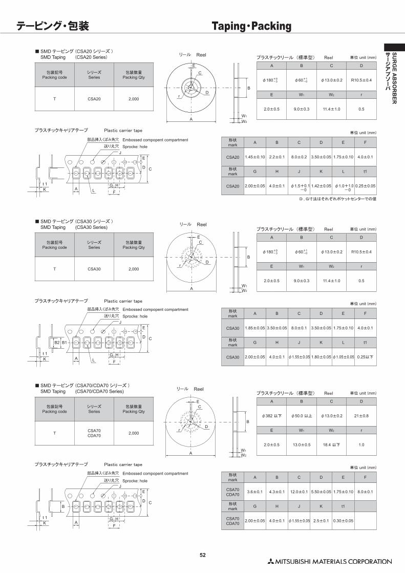
52
SUR
GE A
BSO
RB
ER
サージアブソーバ
テーピング・包装 Taping・Packing
■�SMD テーピング�(CSA20 シリーズ )� SMD Taping� (CSA20 Series)
包装記号Packing code
シリーズSeries
包装数量Packing Qty
T CSA20 2,000
リール Reel
A
C
E
Dr
B
W1
W2
プラスチックリール (標準型)� Reel
A B C D
φ180+0-3 φ60+1
-0 φ13.0±0.2 R10.5±0.4
E W1 W2 r
2.0±0.5 9.0±0.3 11.4±1.0 0.5
単位�unit�(mm)
プラスチックキャリアテープ� Plastic�carrier�tape
A L F
G H
E
Embossed compopent compartment
Sprocke: hole
D C
J
t 1K
部品挿入くぼみ角穴送り丸穴
形状mark A B C D E F
CSA20 1.45±0.10 2.2±0.1 8.0±0.2 3.50±0.05 1.75±0.10 4.0±0.1
形状mark G H J K L t1
CSA20 2.00±0.05 4.0±0.1 φ1.5+0.1-0
1.42±0.05 φ1.0+1.0-0
0.25±0.05
単位�unit�(mm)
D , G寸法はそれぞれポケットセンターでの値
■�SMD テーピング�(CSA30 シリーズ )� SMD Taping (CSA30 Series)
包装記号Packing code
シリーズSeries
包装数量Packing Qty
T CSA30 2,000
EC
DB
W1
W2
r
A
リール Reelプラスチックリール (標準型)� Reel
A B C D
φ180+0-3 φ60+1
-0 φ13.0±0.2 R10.5±0.4
E W1 W2 r
2.0±0.5 9.0±0.3 11.4±1.0 0.5
単位�unit�(mm)
プラスチックキャリアテープ� Plastic�carrier�tape
A L F
G H
E
Embossed compopent compartment
Sprocke: hole
D C
J
B2
t 1K
B1
部品挿入くぼみ角穴送り丸穴
形状mark A B C D E F
CSA30 1.85±0.05 3.50±0.05 8.0±0.1 3.50±0.05 1.75±0.10 4.0±0.1
形状mark G H J K L t1
CSA30 2.00±0.05 4.0±0.1 φ1.55±0.05 1.80±0.05 φ1.05±0.05 0.25以下
単位�unit�(mm)
■�SMD テーピング�(CSA70/CDA70 シリーズ )� SMD Taping (CSA70/CDA70 Series)
包装記号Packing code
シリーズSeries
包装数量Packing Qty
T CSA70CDA70 2,000
EC
DB
W1
W2
r
A
リール Reelプラスチックリール (標準型)� Reel
A B C D
φ382�以下 φ50.0�以上 φ13.0±0.2 21±0.8
E W1 W2 r
2.0±0.5 13.0±0.5 18.4�以下 1.0
単位�unit�(mm)
プラスチックキャリアテープ� Plastic�carrier�tape
AF
G H
E
Embossed compopent compartment
Sprocke: hole
D C
J
t 1K
B
部品挿入くぼみ角穴
送り丸穴形状mark A B C D E F
CSA70CDA70
3.6±0.1 4.3±0.1 12.0±0.1 5.50±0.05 1.75±0.10 8.0±0.1
形状mark G H J K t1
CSA70CDA70
2.00±0.05 4.0±0.1 φ1.55±0.05 2.5±0.1 0.30±0.05
単位�unit�(mm)