조홍기 한국과학기술원 토목공학과 석사과정 오주원 한남대학교 토목공학과 교수 이인원 한국과학기술원 토목공학과 교수
Upload
abraham-hartCategory
view
242download
1
서강대학교 전자공학과윤상원 교수
* “RF Circuit Design: Theory and Applications”, R. Ludwig & P. Bretchko
10. Transmission Line
Microwave & Millimeter-wave Lab. 2
차 례
10-1. Introduction ------------------------------------------------10-2. Transmission Lines -------------------------------------10-3. Equivalent Circuit ---------------------------------------10-4. General Transmission Line Equation ---------10-5. Lossless transmission line --------------------------10-6. Microstrip Transmission Lines --------------------10-7. Terminated Lossless line ----------------------------10-8. Standing Waves ------------------------------------------10-9. Special Termination Conditions -----------------10-10. Sourced and loaded line --------------------------10-11. Power considerations for a line ---------------
3 4 6 811142023283538
Microwave & Millimeter-wave Lab. 3
1-1. Introduction
At RF and microwave frequencies Physical size of circuit approaches to the wave-
length - the phase of ac signal must be considered At higher frequency range For larger size of the circuits
Voltage and Current must be treated as waves Phasor notation is very convenient On the circuit board one dimensional analysis is possible
Distributed circuit approach must be used Lumped element equivalent circuit approach enable us to
use Basic Circuit Theory Impedance is very important as in the Circuit Theory
Microwave & Millimeter-wave Lab. 4
1-2. Transmission Lines
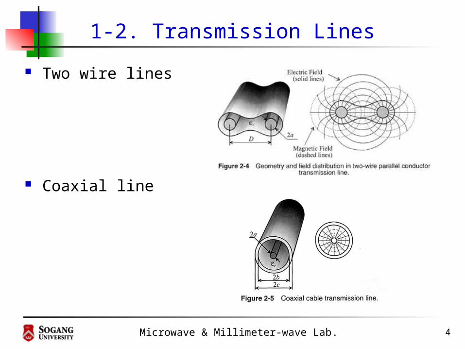
Two wire lines
Coaxial line

Microwave & Millimeter-wave Lab. 5
Transmission lines(2)
Microstrip lines and Striplines
Parallel-plate transmission line

Microwave & Millimeter-wave Lab. 6
1-3. Equivalent Circuit(1)
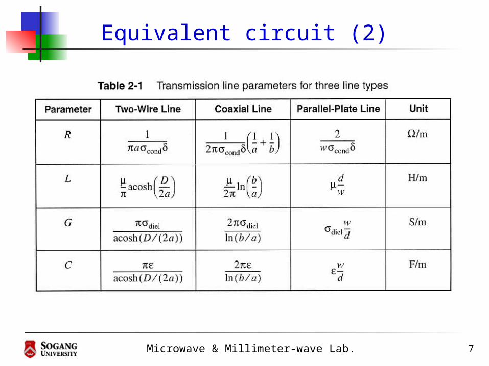
Microwave & Millimeter-wave Lab. 7
Equivalent circuit (2)

Microwave & Millimeter-wave Lab. 8
1-4. General Transmission Line Equation
For a small segment of a transmission line Lumped element equivalent circuit
Apply KVL and KCL
+V(z)
-
I ( z)
+V(z+z)
-
I ( z+z)
z z+z
CzGz
Rz Lz
CjGY
LjRZ
)()()()()(
)()()()()(
zzVYzIzIzIzzI
zzIZzVzVzVzzV

Microwave & Millimeter-wave Lab. 9
General Transmission Line Equation (2)
leads to the differential form as
or
,ZIdz
dV YV
dz
dI
022
2
Ikdz
Id,02
2
2
2
2
Vkdz
VdZYV
dz
Vd
where propagation constant k given as
jCjGLjRZYk
Microwave & Millimeter-wave Lab. 10
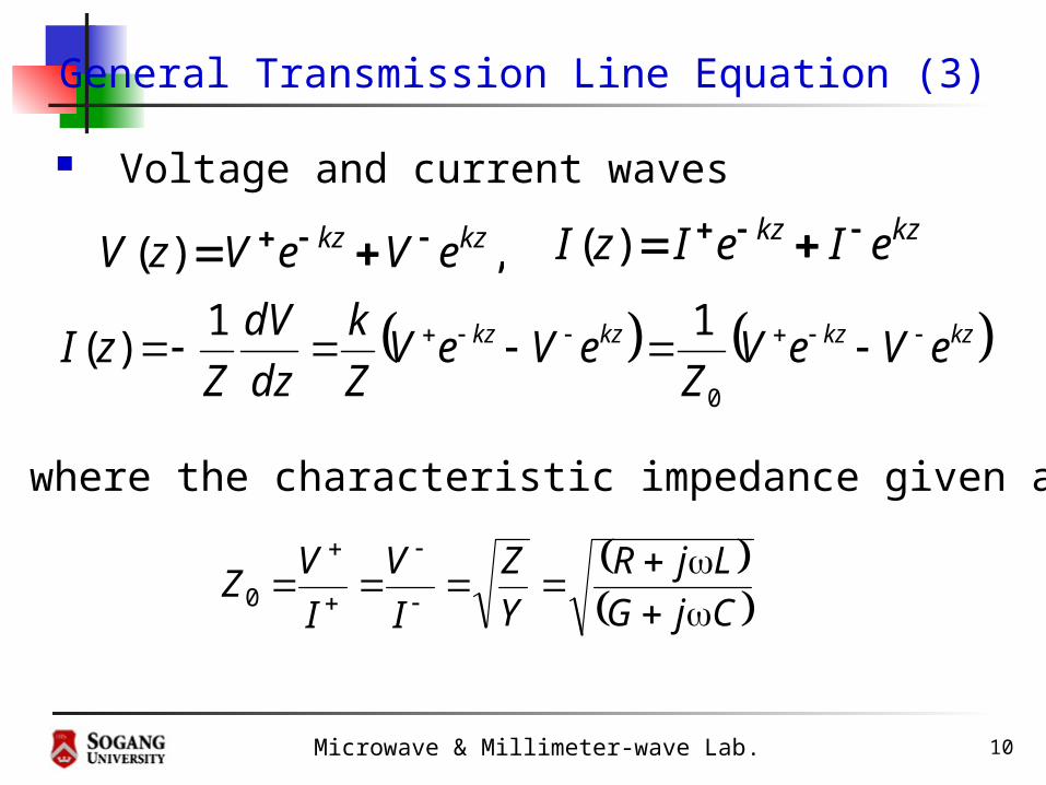
General Transmission Line Equation (3)
Voltage and current waves
,)( kzkz eVeVzV kzkz eIeIzI )(
kzkzkzkz eVeVZ
eVeVZ
k
dz
dV
ZzI
0
11)(
where the characteristic impedance given as
CjG
LjR
Y
Z
I
V
I
VZ
0

Microwave & Millimeter-wave Lab. 11
1-5. Lossless transmission line
C
L
Y
ZZ 0
jLCjZYk
0R and 0G
Propagation constant becomes
Characteristic impedance becomes
Voltage and current waves become
,)( zjzj eVeVzV zjzj eIeIzI )(
Microwave & Millimeter-wave Lab. 12
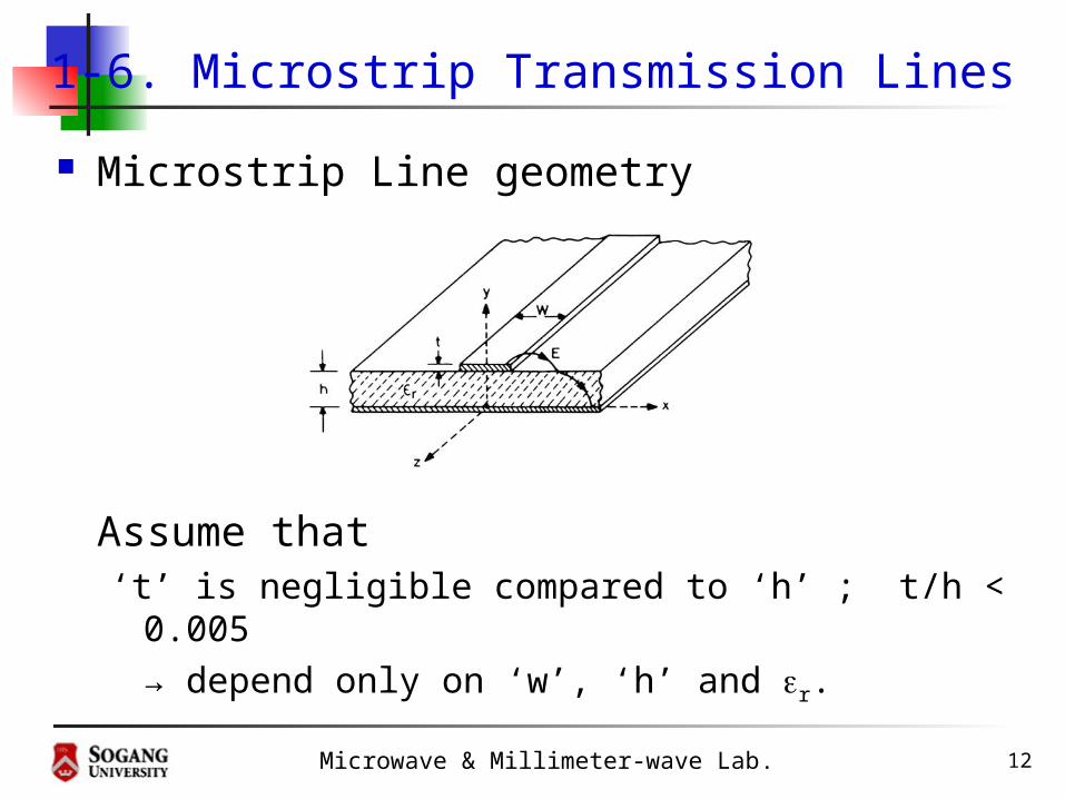
1-6. Microstrip Transmission Lines
Microstrip Line geometry
Assume that ‘t’ is negligible compared to ‘h’ ; t/h < 0.005
→ depend only on ‘w’, ‘h’ and r.

Microwave & Millimeter-wave Lab. 13
Microstrip Transmission Lines (2)
For a narrow lines ; w/h < 1
h
w
w
hZZ
eff
f
48ln
20
: characteristic line
impedance
8.37600 fZ
221
104.01212
1
2
1
h
w
w
hrreff
: wave impedance in
free space
: effective dielectric constant

Microwave & Millimeter-wave Lab. 14
Microstrip Transmission Lines (3)
For a wide lines ; w/h > 1
Wavelength
444.1ln
32
393.10
hw
hw
ZZ
eff
f
: characteristic
impedance
21
1212
1
2
1
w
hrreff
: effective
dielectric constant
effeff
p c
ff
v
01

Microwave & Millimeter-wave Lab. 15
Microstrip Transmission Lines (4)
Z0 and εeff are plotted as w/h and εr

Microwave & Millimeter-wave Lab. 16
Microstrip Transmission Lines (5)
Assuming an infinitely thin line conductor,w/h ≤ 2 ;
w/h ≥ 2 ;
2
82
A
A
e
e
h
w
rr
rr
fZ
ZA
11.0
23.01
1
2
12 0
rr
r BBBh
w
61.0
39.01ln2
112ln1
2
r
f
Z
ZB
02

Microwave & Millimeter-wave Lab. 17
Microstrip Transmission Lines (6)
Corrections for nonzero strip thickness t ;
twπh/wx
hwhx
t
xtwweff 22 if 2
2t 2/ if
21
Microwave & Millimeter-wave Lab. 18
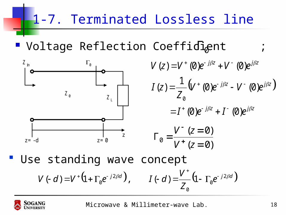
1-7. Terminated Lossless line
Voltage Reflection Coefficient ;
z=- d z=0z
Z0 Z L
Z in 0
zjzj
zjzj
zjzj
eIeI
eVeVZ
zI
eVeVzV
)0()0(
)0()0(1
)(
)0()0()(
0
djdj eZ
VdIeVdV 2
00
20 1)( , 1)(
Use standing wave concept)0(
)0(Γ0
zV
zV
0Γ

Microwave & Millimeter-wave Lab. 19
Terminated Transmission line (2)
dj
dj
ine
eZ
dI
dVZ
20
20
01
1
)(
)(
Input impedance ;
Input impedance at ;0z
0
00 1
1
)0(
)0()0(
ZI
VZZ Lin
1
1
0
00
L
L
L
L
Z
Z
ZZ
ZZ : Reflection coefficient
at load
dz
Microwave & Millimeter-wave Lab. 20
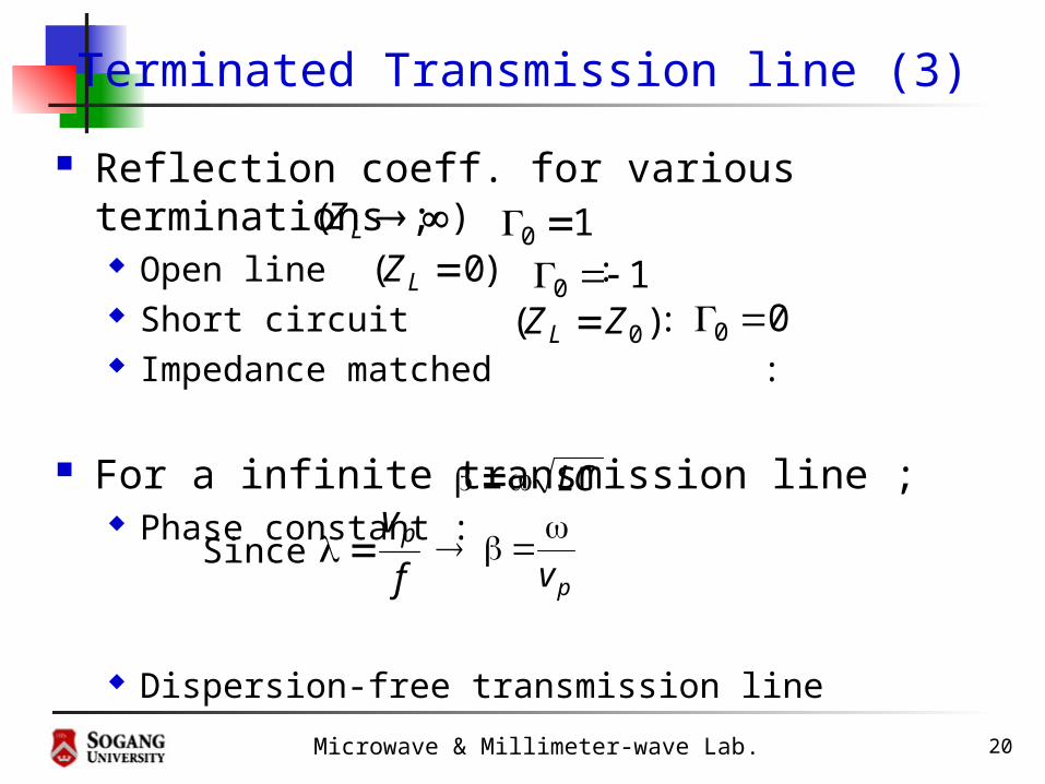
Terminated Transmission line (3)
Reflection coeff. for various terminations ; Open line : Short circuit : Impedance matched :
For a infinite transmission line ; Phase constant :
Dispersion-free transmission line
)( LZ 10 )0( LZ 10
)( 0ZZL 00
LC
pv
f
vpSince
Microwave & Millimeter-wave Lab. 21
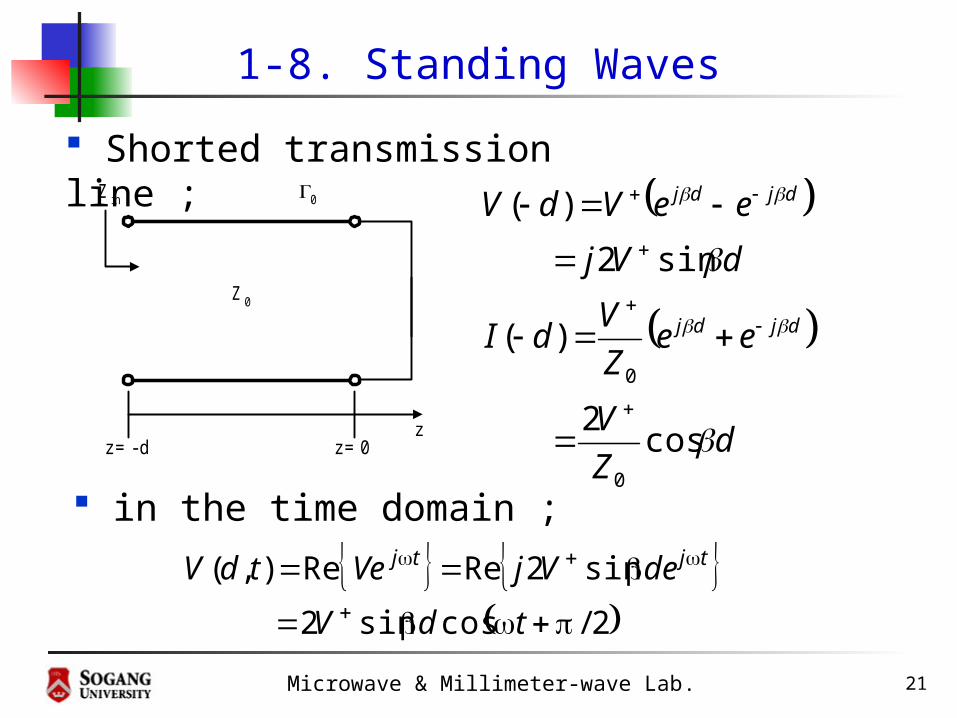
1-8. Standing Waves
z=- d z=0z
Z 0
Z in 0
Shorted transmission line ;
dZ
V
eeZ
VdI
dVj
eeVdV
djdj
djdj
cos2
)(
sin2
)(
0
0
in the time domain ;
2/cossin2
sin2Re Re ),(
tdV
deVjVetdV tjtj

Microwave & Millimeter-wave Lab. 22
Standing Waves(2)

Microwave & Millimeter-wave Lab. 23
Standing Waves(3)
z=- d z=0z
Z 0
Z L
Z in 0
V+
V -
V+ e - jd
0V+ e - jd0V+ e - j2d
Standing wave expressions ;
dj
dj
e
eV
VVdV
2
0
20
(d)
1
)(
djeVdA
dZ
dAdI
ddAdV
)(
)(1)(
)(
)(1)()(
0
Standing wave ratio(SWR) ;
11
1SWR
0
0
min
max
min
max
I
I
V
V

Microwave & Millimeter-wave Lab. 24
Standing Waves(4)
Microwave & Millimeter-wave Lab. 25
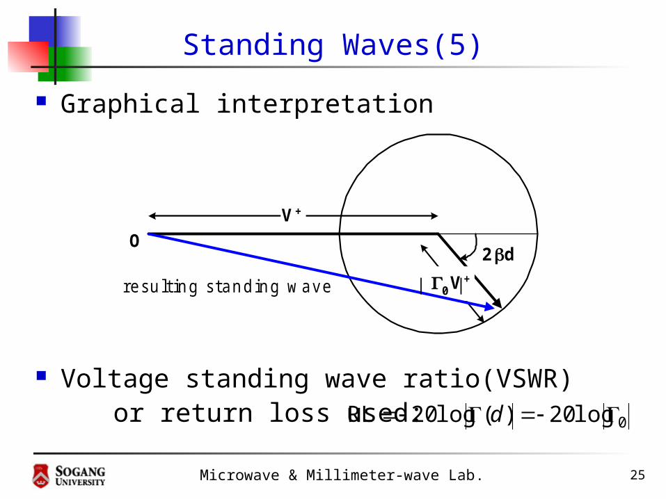
Standing Waves(5)
Graphical interpretation
Voltage standing wave ratio(VSWR) or return loss used: 0log20)(log20RL d
V+
0V+
2d
resulting standing w ave
O
| |

Microwave & Millimeter-wave Lab. 26
1-9. Special Termination Conditions
Input impedance of terminated line ;
z=- d z=0z
Z 0
Z L
Z in 0
V+
V -
V+ e - jd
0V+ e - jd0V+ e - j2d
dj
dj
ineV
eVZ
dI
dVdZ
2
0
20
01
1
)(
)()(
or
)(1
)(1)( 0 d
dZdZin
djZZ
djZZZ
eZZ
ZZ
eZZ
ZZ
ZdZL
L
dj
L
L
dj
L
L
in
tan
tan
1
1
)(0
00
2
0
0
2
0
0
0

Microwave & Millimeter-wave Lab. 27
Special Termination Conditions(2)
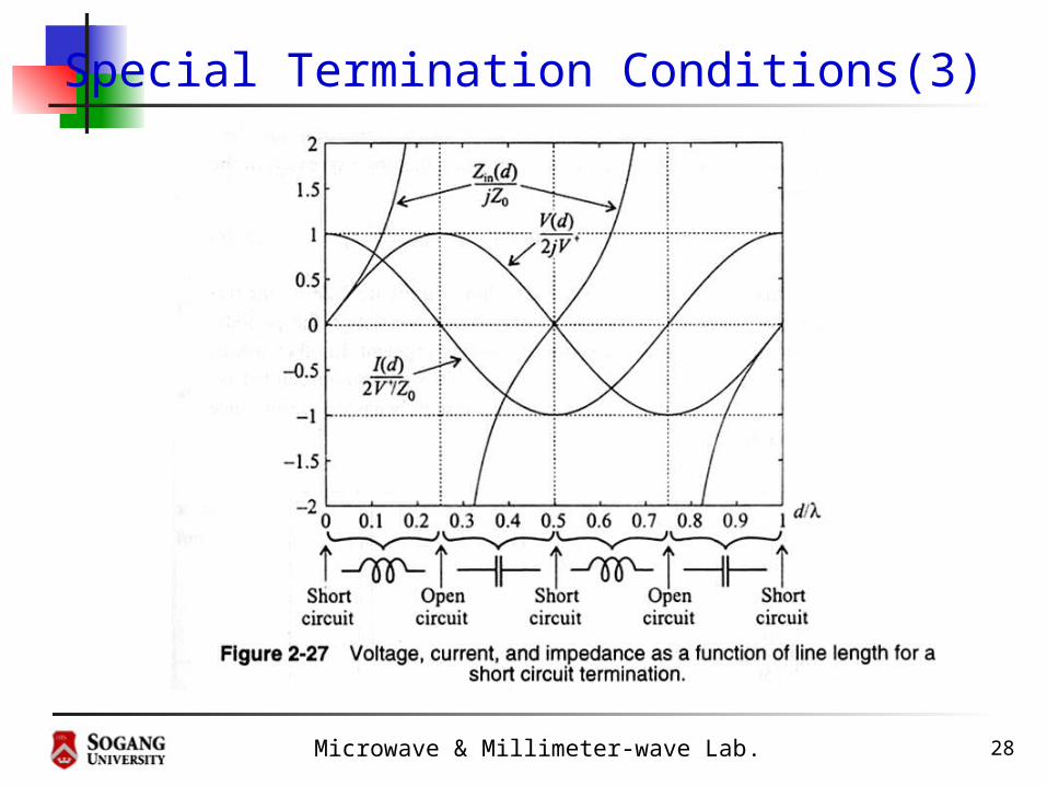
Short Circuit Transmission Line
z=- d z=0z
Z 0
Z in 0=- 1
djZdZin tan)( 0
dZ
V
eeZ
VdI
dVj
eeVdV
djdj
djdj
cos2
)(
sin2
)(
0
0
00
00 tan
tan)(
LZL
Lin djZZ
djZZZdZ
Microwave & Millimeter-wave Lab. 28
Special Termination Conditions(3)

Microwave & Millimeter-wave Lab. 29
Special Termination Conditions(4)
Open-circuit transmission line
z=- d z=0z
Z 0
Z in 0 =1
LZL
Lin djZZ
djZZZdZ
tan
tan)(
0
00
djZdZin cot)( 0
dZ
Vj
eeZ
VdI
dV
eeVdV
djdj
djdj
sin2
)(
cos2
)(
0
0

Microwave & Millimeter-wave Lab. 30
Special Termination Conditions(5)
Microwave & Millimeter-wave Lab. 31
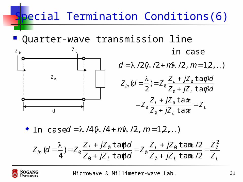
Special Termination Conditions(6)
Quarter-wave transmission line in case
In case
d
Z0
Z LZ in
),2,1 ,2/2/(2/ mmd
LL
L
L
Lin
ZjZZ
jZZZ
djZZ
djZZZdZ
tan
tan
tan
tan)
2(
0
00
0
00
),2,1 ,2/4/(4/ mmd
LL
L
L
Lin Z
Z
jZZ
jZZZ
djZZ
djZZZdZ
20
0
00
0
00 2/tan
2/tan
tan
tan)
4(
Microwave & Millimeter-wave Lab. 32
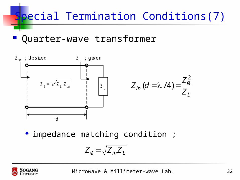
Special Termination Conditions(7)
Quarter-wave transformer
impedance matching condition ;
d
Z in ; desired Z L ; given
Z LZ 0 = Z L Z in
Lin Z
ZdZ
20 )4/(
LinZZZ 0
Microwave & Millimeter-wave Lab. 33
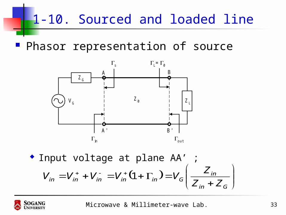
1-10. Sourced and loaded line
Phasor representation of source
Input voltage at plane AA’ ;
Z0 Z LVG
L=0
ZG
s
in out
A
A'
B
B'
Gin
inGininininin ZZ
ZVVVVV 1
Microwave & Millimeter-wave Lab. 34
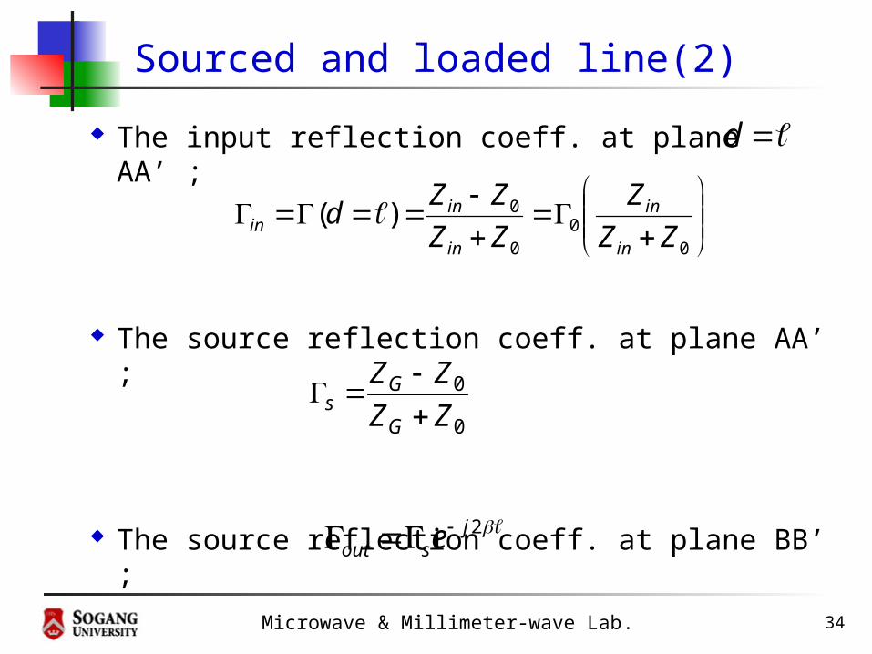
Sourced and loaded line(2)
The input reflection coeff. at plane AA’ ;
The source reflection coeff. at plane AA’ ;
The source reflection coeff. at plane BB’ ;
d
0
00
0)(ZZ
Z
ZZ
ZZd
in
in
in
inin
0
0
ZZ
ZZ
G
Gs
2jsout e
Microwave & Millimeter-wave Lab. 35
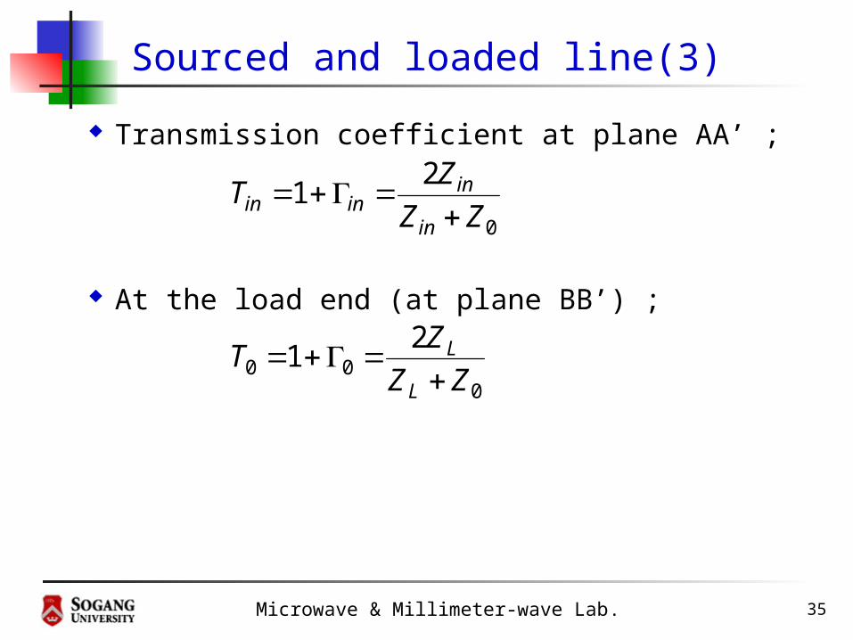
Sourced and loaded line(3)
Transmission coefficient at plane AA’ ;
At the load end (at plane BB’) ;
0
21
ZZ
ZT
in
ininin
000
21
ZZ
ZT
L
L
Microwave & Millimeter-wave Lab. 36
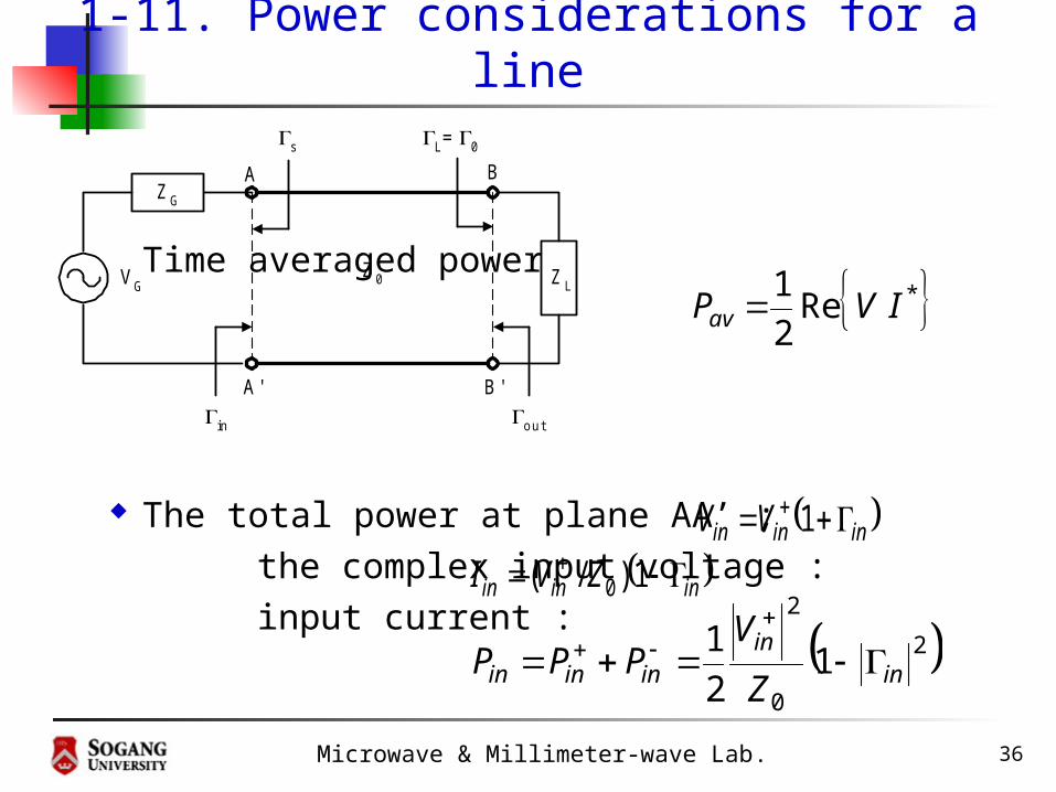
1-11. Power considerations for a line
Time averaged power
The total power at plane AA’ ; the complex input voltage : input current :
Z0 Z LVG
L=0
ZG
s
in out
A
A'
B
B'
* Re 2
1IVPav
ininin VV 1
ininin ZVI 1)/( 0
2
0
2
12
1in
inininin Z
VPPP

Microwave & Millimeter-wave Lab. 37
Power considerations for a line(2)
In terms of generator voltage ;
The input and the generator impedances ;
The generator voltage in terms of
Gin
in
in
G
in
inin ZZ
ZVVV
11
s
sG
in
inin ZZZZ
1
1 ,
1
100
sin and
2
2
2
0
2
11
1
8
1in
ins
sGin Z
VP
Microwave & Millimeter-wave Lab. 38
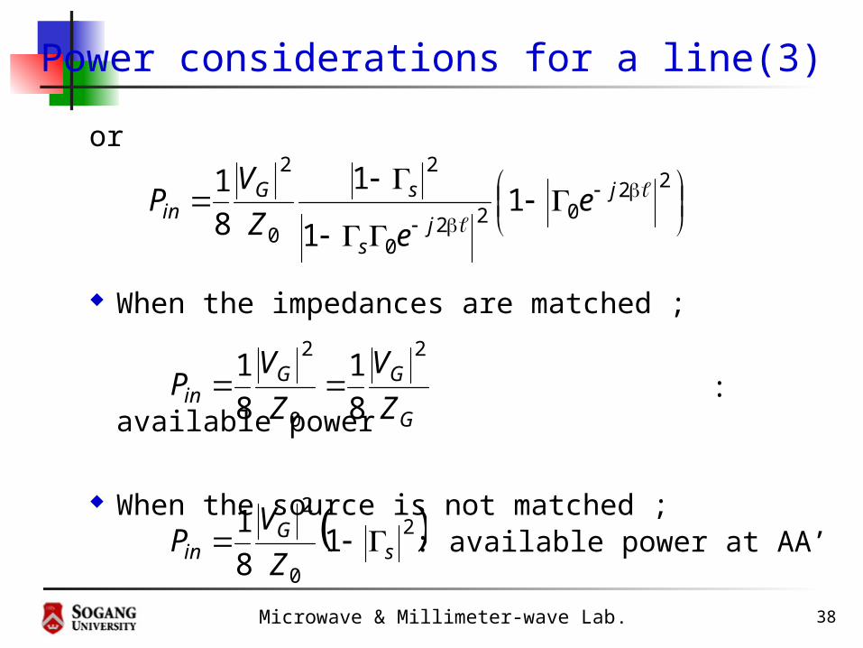
Power considerations for a line(3)
or
When the impedances are matched ;
: available power
When the source is not matched ;
22022
0
2
0
2
11
1
8
1
j
js
sGin e
eZ
VP
G
GGin Z
V
Z
VP
2
0
2
8
1
8
1
2
0
2
18
1s
Gin Z
VP : available power at AA’