橡 ED-4701 1 开䔀开⸀倀䐀 - JEITA - home.jeita.or.jp · PDF filesemiconductor devices...
25
Standard of Japan Electronics and Information Technology Industries Association EIAJ ED- 4701/100 Environmental and endurance test methods for semiconductor devices (Life test I) Established in August, 2001 Prepared by Technical Standardization Committee on Semiconductor Devices Published by Japan Electronics and Information Technology Industries Association 11, Kanda Surugadai 3-chome, Chiyoda-ku, Tokyo 101-0062, Japan Printed in Japan
Transcript of 橡 ED-4701 1 开䔀开⸀倀䐀 - JEITA - home.jeita.or.jp · PDF filesemiconductor devices...
Standard of Japan Electronics and Information Technology Industries Association
EIAJ ED-4701/100
Environmental and endurance test methods forsemiconductor devices
(Life test I)
Established in August, 2001
Prepared by
Technical Standardization Committee on Semiconductor Devices
Published by
Japan Electronics and Information Technology Industries Association
11, Kanda Surugadai 3-chome, Chiyoda-ku, Tokyo 101-0062, Japan
Printed in Japan
Translation without guarantee in the event of any doubt arising, the original standard in Japanese is
to be evidence.
JEITA standards are established independently to any existing patents on the products, materials or
processes they cover.
JEITA assumes absolutely no responsibility toward parties applying these standards or toward patent owners.
2001 by the Japan Electronics and Information Technology Industries Association
All rights reserved. No part of this standards may be reproduced in any form or by any means
without prior permission in writing from the publisher.

EIAJ ED-4701/100
CONTENTS
Page
1. SCOPE ............................................................................................................................................... 1
2. DEFINITION OF TERMS .................................................................................................................. 1
3. PRECAUTIONS ................................................................................................................................. 1
4. TEST METHODS............................................................................................................................... 1
COMMENTS ......................................................................................................................................... 3
APPENDIX ............................................................................................................................................ 9
TEST METHOD 101 STEADY STATE OPERATING LIFE ....................................................... 11
TEST METHOD 102 TEMPERATURE HUMIDITY BIAS (THB).............................................. 15
TEST METHOD 103 TEMPERATURE HUMIDITY STORAGE ................................................ 23
TEST METHOD 104 MOISTURE SOAKING AND SOLDERING
HEAT STRESS SERIES TEST .................................................................. 29
TEST METHOD 105 TEMPERATURE CYCLE.......................................................................... 33
TEST METHOD 106 INTERMITTENT OPERATING LIFE ....................................................... 41

EIAJ ED-4701/100
Standard of Japan Electronics and Information Technology Industries Association
Environmental and endurance test methods for semiconductor devices(Life test I)
1. SCOPEThese standards provide for environmental test methods and endurance test methods (especially life
tests) aimed at evaluating the resistance and the endurance of discrete semiconductor devices and
integrated circuits (hereinafter generically called semiconductor devices) used in electronic
equipment mainly for general industrial applications and consumer applications, under the various
environmental conditions of various kinds that occur during their use, storage and transportation.
2. DEFINITION OF TERMSThe definitions of the technical terms used in these standards and in the relevant specifications are
given in EIAJ ED-4701/001 "Environmental and endurance test methods for semiconductor devices
(General)."
3. PRECAUTIONSThe precautions used in these standards and in the relevant specifications are given in EIAJ ED-
4701/001 "Environmental and endurance test methods for semiconductor devices (General)."
4. TEST METHODSRefer to the Appendix for the test methods.
Remarks:
The various test methods are arranged independently for the sake of more convenient use of these
standards.

EIAJ ED-4701/100
COMMENTS
1. PURPOSE OF ESTABLISHMENT OF THESE STANDARDSBefore the establishment of these standards, the standardization referring to EIAJ ED-4701
"Environmental and endurance test methods for semiconductor devices" established on Feb., 1992,
and EIAJ has issued amendments, whenever the revision and also new test method establish.
However, it is recondite where the latest test methods are entered, it was resulting the confusion of
users. So establishment of new numbering system that is easy to use both users and manufacturers
was decided, and reached to the issuance in this time.
Electronic Industries Association of Japan (EIAJ) and The Japan Electronic Industry Development
Association (JEIDA) have merged effective November 1,2000, the Japan Electronics and Information
Technology Industries Association (JEITA).
2. EVOLUTION OF THE DELIBERATIONSThe revision of the standards and new numbering system have been deliberated by "Sub-Committee
on Semiconductor Devices Reliability" of the Technical Standardization Committee on
Semiconductor Devices/Semiconductor Devices Reliability Group from Apr., 2000. Though to issue
as a separate standard every each test method was considered, it made to issue with the system like
the following.
(a) EIAJ ED-4701/001 Environmental and endurance test methods for semiconductor devices
(General)
(b) EIAJ ED-4701/100 Environmental and endurance test methods for semiconductor devices
(Life test I)
101 Steady state operating life
102 Temperature humidity bias (THB)
103 Temperature humidity storage
104 Moisture soaking and soldering heat stress series test
105 Temperature cycle
106 Intermittent operating life
(c) EIAJ ED-4701/200 Environmental and endurance test methods for semiconductor devices
(Life test II)
201 High temperature storage
202 Low temperature storage
203 Moisture resistance (Cyclic)
204 Salt mist
(d) EIAJ ED-4701/300 Environmental and endurance test methods for semiconductor devices
(Stress test I)
301 Resistance to soldering heat for surface mounting devices (SMD)
302 Resistance to soldering heat (excluding surface mounting devices)
303 Solderability
304 Human body model electrostatic discharge (HBM/ESD)

EIAJ ED-4701/100
305 Charged device model electrostatic discharge (CDM/ESD)
306 Latch-up
307 Thermal shock
(e) EIAJ ED-4701/400 Environmental and endurance test methods for semiconductor devices
(Stress test II)
401 Terminal strength
402 Mounting strength
403 Vibration (Sinusoidal)
404 Shock
405 Acceleration (Steady state)
(f) EIAJ ED-4701/500 Environmental and endurance test methods for semiconductor devices
(Miscellaneous)
501 Permanence of marking
502 Flammability tests of plastic-encapsulated devices (Externally induced)
503 Seal
504 Low air pressure
Both life and stress tests are divided into two standards as "I" and "II". "I" is including test method
that is thought that revision occurs comparatively from now on.
3. DELIBERATING MEMBERSDeliberation of this standard has been made by "Sub-Committee on Semiconductor Devices
Reliability" of the Technical Standardization Committee on Semiconductor Devices/Semiconductor
Devices Reliability Group.
Below are listed the members of deliberation of this standard.
<Technical Standardization Committee on Semiconductor Devices/Semiconductor Devices
Reliability Group>
Chairman Mitsutoshi Ito NEC Corp.
<Semiconductor Devices Reliability Group>
Chairman Kazutoshi Miyamoto Mitsubishi Electric Corp.
<Sub-Committee on Semiconductor Devices Reliability>
Chairman Tetsuaki Wada Matsushita Electronics Co., Ltd.
Vice Chairman Masaki Tanaka Hitachi Ltd.
Member Hideaki Yoshida Oki Electric Industry Co., Ltd.
Osamu Nakayama Kawasaki Microelectronics, Inc.
Shizuo Kunita Sanken Electric Co., Ltd.
Toru Katou Sanyo Electric Co., Ltd.
Nobuyuki Kawayoshi Sharp Corp.
Makoto Kanayama Shindengen Electric Mfg. Co., Ltd.
Kouichi Mannen New Japan Radio Co., Ltd.

EIAJ ED-4701/100
Hiroyoshi Odaira Seiko Epson Corp.
Atsushi Natsume Sony Corp.
Tetsuji Matsuura Toshiba Corp.
Yasuyuki Igarashi IBM Japan, Ltd.
Satoru Sadaike Texas Instruments Japan Ltd.
Muramasu Omori NEC Corp.
Toshiki Yamaguchi Fujitsu Ltd.
Naohiro Yasuda Fuji Electric Co., Ltd.
Junichi Mitsuhashi Mitsubishi Electric Corp.
Masashi Kusuda Mitsumi Electric Co., Ltd.
Kohki Ohara Ricoh Co., Ltd.
Takahiro Ito Rohm Co., Ltd.
Special Members Yasuhiro Fukuda Oki Electric Industry Co., Ltd.
Kouji Obinata Sony Corp.
Takeshi Watanabe NEC Corp.

EIAJ ED-4701/100
APPENDIX

EIAJ ED-4701/100
TEST METHOD 101
STEADY STATE OPERATING LIFE
1. SCOPEThis standard provides for the method to evaluate the endurance of semiconductor devices when they
are submitted to electric stress and thermal stress of long duration.
Remarks:Care must be taken when executing this test, because the device temperature may exceed the ambient
preset temperature and rise conspicuously due to internally dissipated heat from the device.
2. TEST EQUIPMENTEquipment to be used in this test should consist of a chamber capable to keep the specified test
temperature within the specified tolerance, the power supply capable to generate the specified AC or
DC voltages, and the board to make electrical contact to the terminals of devices under test with
socket or other mounting method, having heat.
2.1 CircuitryThe biasing and operating schemes shall consider the limitations of the device. Device thermal
characterization shall be considered to ensure that the temperature of "Hot Spots" on the die does not
exceed maximum rated junction temperature (Tjmax).
2.2 Device mountingDevice mounting shall consider the thermal capacity to minimize adverse effects during test.
Remarks:
When he SMD is mounted on the test board for evaluation, the relevant conditions (substrate material,
land size, soldering method, flux cleaning, etc.) should be specified in the relevant specifications.
2.3 Environmental chamberThe environmental chamber shall be capable of maintaining the specified ambient temperature within
a tolerance of ±5°C throughout the chamber while a test is being conducted.
3. PROCEDURE
3.1 Initial measurementThe initial measurements should be carried out in conformity with the items and conditions specified
in relevant specifications.
3.2 Operating mode and test circuitOperating mode and test circuit should be in conformity with the stipulations of the relevant
specifications.
(1) High-Temperature Operating Life (HTOL)
The HTOL test is configured to exercise the maximum number of nodes feasible. The supply
voltages and clock frequency should be in conformity with the stipulations of the relevant
specifications.
(2) High-Temperature Reverse-Bias (HTRB)
The HTRB test is configured to apply the maximum rated DC reverse voltage (VRMAX) to the
devices that remain in a static mode of operation for the duration of the test. The supply voltage

EIAJ ED-4701/100
should be in conformity with the stipulations of the relevant specifications.
(3) High-Temperature Forward-Bias (HTFB)
The HTFB test is configured to apply power to the device samples so as to forward bias major
power-handling junctions. The devices are operated in either a static or pulsed operating mode.
Operating condition should be conformity with the stipulations of the relevant specifications.
The HTFB test is typically used for diodes, transistors or power driver integrated circuits.
3.3 Ambient temperatureThe ambient temperature should be 125°C±5°C, unless otherwise exceeded the maximum rated
junction temperature (Tjmax).
Remarks:
Care must be taken because the maximum rated junction temperature (Tjmax) may be exceeded due to
internally dissipated heat from the specimen.
3.4 Test durationThe test duration should be 1000 hours (+168 hours, -0 hours), unless otherwise specified. If interim
measurements are deemed necessary, they may be chosen from the following standard time intervals,
as time to perform such measurements.
24 hours (+ 8 hours, - 0 hours)
48 hours (+ 8 hours, -0 hours)
96 hours (+24 hours, -0 hours)
168 hours (+72 hours, -0 hours)
504 hours (+168 hours,-0 hours)
Remarks:
The time spent reducing chamber conditions to room ambient and conducting the interim
measurements shall not be considered a portion of the total specified test duration.
3.5 Post treatmentAt the end of the test period, the specimen should be stored under normal conditions from 2 hours to
24 hours.
3.6 End-point measurementThe end-point measurements should be carried out in conformity with the items and conditions
specified in the relevant specifications.
Remarks:
Electrical end-point testing shall be completed within 48 hours of removal of bias from devices.
4. INFORMATION TO BE GIVEN IN THE RELEVANT SPECIFICATIONS(1) Specimen mounting method (When required) [Refer to 2.2 ]
(2) Items and conditions of the initial measurements [Refer to 3.1 ]
(3) Operating mode and test circuit [Refer to 3.2 ]
(4) Ambient temperature (When using temperatures other than 125°C) [Refer to 3.3 ]
(5) Test duration (When using test duration other than 1000 hours) [Refer to 3.4 ]
(6) Post treatment (When executing post treatment other than the specified ones) [Refer to 3.5 ]
(7) Items and conditions of the end-point measurements. [Refer to 3.6 ]

EIAJ ED-4701/100
TEST METHOD 102
TEMPERATURE HUMIDITY BIAS (THB)
1. SCOPEThis standard provides for the methods to evaluate the endurance of semiconductor devices when
used in high temperature and high humidity ambient.
Remarks1. At the beginning, this test was designed by assuming the evaluation of the endurance of
semiconductor devices contained mainly in resin sealed packages, against the corrosion
phenomenon of metallic wiring on the chip.
Recently, however, this test is being used to accelerate the leak phenomenon due to infiltration of
moisture through the passivation film and as a part of various kinds of series tests, but care must
be taken because accelerability data are not necessarily well known, and it may bring about
failure modes that do not occur in the field.
2. Care must be taken because failure modes consisting of short-circuit (leak) between external
leads by plating metal, that do not occur in the field, may occur under condition C (temperature
85°C, humidity 85%), and Unsaturated Pressurized Vapor Test
2. TEST EQUIPMENT
2.1 Capacity of the test equipmentEquipment to be used in this test should be provided with a chamber capable to keep the test
temperature and humidity specified in section 3.2.2(3) for long time, a power supply, and whenever
required a timer to turn the power supply ON and OFF during the specified time, when required.
2.2 Material and construction of the chamberThe chamber should be made of material that does not react under high humidity conditions.
Moreover, water condensed on the ceiling of the chamber should not drop on the specimen.
2.3 Water to be used in testWater to be used in the tests should be distilled water or deionized water, with pH from 6.0 to 7.2,and
resistivity of 500 Ohm-m or more at 23°C.
3. PROCEDUREWhen the specimen is a plastic-molded SMD, carry out the moisture soaking and soldering heat stress
treatment specified in test method 104 (moisture soaking and soldering heat stress series tests)before
executing this test.
3.1 Initial measurementCarry out the initial measurements in conformity with the items and conditions specified in the
relevant specifications.
3.2 TestsApply the specified voltage on the specimen in the test chamber kept at high temperature and high
humidity conditions. When required turn the power ON and OFF cyclically. When putting the
specimen in and out of the chamber, make sure that water drops are not stuck to the specimen and do
not dip it in water.

EIAJ ED-4701/100
Remarks:When the SMD is to be mounted on a jig for evaluation, the relevant conditions (substrate material, size
of the land, soldering method. flux cleaning. etc.) should be specified in the relevant specifications.
3.2.1 Test circuitThe test circuit should be in conformity with the relevant specifications.
3.2.2 Test conditions
(1) Voltage applicationApply voltage continuously in conformity with the conditions specified in the relevant specifications.
Apply the voltage intermittently when the power dissipation is large, however, and turn the power
supply ON and OFF in conformity with the time specified in the relevant specifications.
Remarks:1. The applied voltage should be in conformity with the stipulations of the relevant specifications,
and it is desirable to restrict the internal heat generation so as to minimize power dissipation.
2. The relative humidity of the chip surface in the package decreases due to heat generation of the
chip when the device has large power dissipation, and corrosion becomes less probable. In this
case, it is recommendable to turn the power ON and OFF in order to attain more effective results
related to corrosion. In general, continuous power application is desirable when the power
dissipation is smaller than 100mW, and intermittent power application consisting of 1-hour ON
and 3-hour OFF is recommended when the power dissipation exceeds 100mW.
(2) Tolerance of the applied voltageThe tolerance of the applied voltage should be within ±5% of the preset value.
(3) High temperature and high humidity conditions
Select the temperature and humidity conditions out of those ones of Table 1, and apply the
Conditions C unless otherwise specified. Under condition D, E, and F (Unsaturated Pressurized
Vapor Test), the temperature and the humidity from the start to the end of the test should be
controlled in conformity with the profile of Figure 1, unless otherwise specified.
The relative humidity in the chamber during the heating and humidification phase as well as in
the cooling and dehumidification phase should be kept from 50% to 85%.
(4) Test duration
Test duration should be refered to Table 1, except when otherwise specified. Under condition
D, E, and F (Unsaturated Pressurized Vapor Test), the time count should be started when the
vapor pressure and temperature reach stable state as shown in Figure 1.
Table 1 TEMPERATURE HUMIDITY STORAGE TEST CONDITIONSTest code
Test code Temperature Humidity Test duration Vapor pressure(1)
°C % h Pa
A 40±2 90±5 1000+168/-24 -B 60±2 90±5 1000+168/-24 -CDEF
85±2110±2120±2130±2
85±585±585±585±5
1000+168/-24 -1.2 × 10⁵
1.7 × 10⁵
2.3 × 10⁵
Note(1) Reference value
Condition D, E, and F is called Unsaturated Pressurized Vapor Test.

EIAJ ED-4701/100
Figure 1 UNSATURATED PRESSURIZED VAPOR TEST CONDITIONS FROFILE
3.3 Post treatmentAfter finishing the tests, leave the specimen standing under normal conditions, from 2 hours to 24
hours.
Remarks:Under condition D, E, and F (Unsaturated Pressurized Vapor Test), special care should be taken when
handling the specimen after finishing the test,because failure modes differnt from those ones of the
tests may occur due to condensation, sudden changes in the temperature and pressure, and other
relevant factors. After finishing the test, remove the specimen from the chamber after confirming that
the interior of the chamber has returned approximately to the normal condition in conformity with the
specified temperature and humidity profile, and then leave the specimen in room temperature.
3.4 End-point measurementCarry out the end-point measurements in conformity with the items and conditions specified in the
relevant specifications. These measurements should be carried out within 48 hours under normal
conditions after the completion of the tests, except when other specified.
Remarks:
In case of expending more completion time of the measurements than 48 hours, the specimen should
be storaged in suitable storage conditions such as no influence of test results.
%RH
85
50
°C
100
95
RT
Pa
0
<Relative humidity>
<Temperature>
<Vapor pressure>
1.5h ± 15min 0.5h - 1h(Natural cooling)
TimeTest time

EIAJ ED-4701/100
4. INFORMATION TO BE GIVEN IN THE RELEVANT SPECIFICATIONS(1) Items and conditions of the intial measurements [Refer to 3.1]
(2) Specimen mounting method (When required) [Refer to 3.2]
(3) Test circuit [Refer to 3.2.1]
(4) Voltage application conditions and power ON/OFF cycle
(When using conditions and cycles other than the specified ones) [Refer to 3.2.2(1)]
(5) High temperature and high humidity conditions
(When using conditions other than the specified ones) [Refer to 3.2.2(3)]
(6) Test duration (When using duration other than 1000 hours) [Refer to 3.2.2(4)]
(7) Post treatment (When executing post treatment other than the specified ones)
[Refer to 3.3]
(8) Item and conditions of the end-point measurements [Refer to 3.4]
(9) Storage conditions to the measurements
(When using storage conditions than the specified ones) [Refer to 3.4]
EIAJ ED-4701/100
TEST METHOD 103
TEMPERATURE HUMIDITY STORAGE
1. SCOPEThis standard dprovides for the methods to evalute the endurance of plastic moulded package
semiconductor devices when they are used in high temperature and high humidity ambient.
Remarks:1. This test have been designed with the object of evaluating the endurance, against corrosion, of
metallic wiring of chips of semiconductor devices contained mainly in plastic molded packages.
Recently it is also being used as a means to accelerate the leak phenomenon due to the moisture
penetration through the passivation film and as a pre-conditioning for various kinds of tests, but
care must be taken because data related to accelerability are not clearly known yet.
2. Care must be taken because failure modes consisting of short-circuit (leak) between external
leads by plating metal, that do not occur in the field, may occur under condition C (temperature
85°C,humidity 85%), and Unsaturated Pressurized Vapor Test (condition D, E, and F).
2. TEST EQUIPMENT
2.1 Capacity of the equipmentChamber to be used in this test should be capable to keep the test temperature and humidity
conditions specified in section 3.2 for long time.
2.2 Materials and construction of the thermostatic/humidistatic chamberThe chamber should be made of material that does not react under high humidity conditions.
Moreover, water condensed on the ceiling of the chamber should not drop on the specimen.
2.3 Water to be used in testWater to be used in the tests should be distilled water or deionized water, with pH from 6.0 to
7.2,and resistivity of 500 Ohm-m or more at 23°C temperature.
3. PROCEDUREWhen the specimen is plastic-molded SMD, carry out the moisture soaking and soldering heat stress
treatment specified in the test method 104 (Moisture soaking and soldering heat stress test series)
before executing this test.
3.1 Initial measurementCarry out the initial measurements in conformity with the items and conditions specified in the
relevant specifications.
3.2 TestsPlace the specimen in the chamber kept at high temperature and high humidity conditions. When
putting the specimen in and out of the chamber, make sure that water drops not to be stuck to the
specimen and not to dip it in water.
Remarks:
When the SMD is to be mounted on the jig for evaluation, the relevant conditions (board materials,
size of the land, soldering method, flux cleaning, etc.) should be specified in the relevant
specifications.
EIAJ ED-4701/100
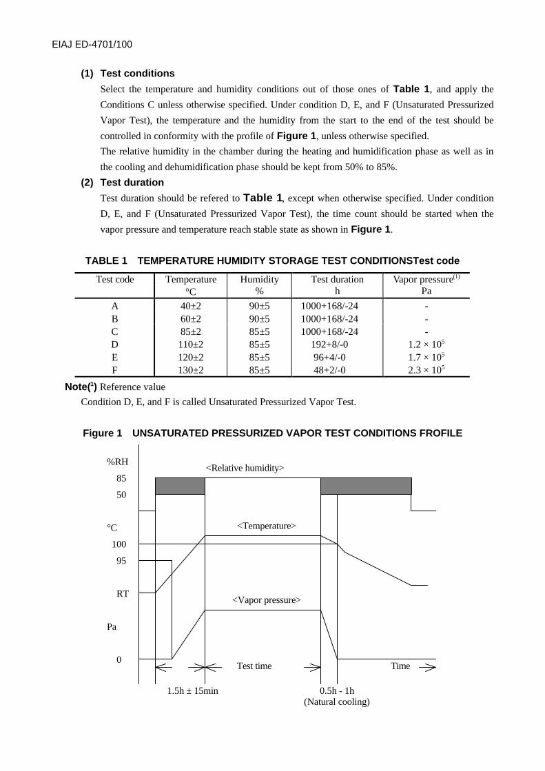
(1) Test conditions
Select the temperature and humidity conditions out of those ones of Table 1, and apply the
Conditions C unless otherwise specified. Under condition D, E, and F (Unsaturated Pressurized
Vapor Test), the temperature and the humidity from the start to the end of the test should be
controlled in conformity with the profile of Figure 1, unless otherwise specified.
The relative humidity in the chamber during the heating and humidification phase as well as in
the cooling and dehumidification phase should be kept from 50% to 85%.
(2) Test duration
Test duration should be refered to Table 1, except when otherwise specified. Under condition
D, E, and F (Unsaturated Pressurized Vapor Test), the time count should be started when the
vapor pressure and temperature reach stable state as shown in Figure 1.
TABLE 1 TEMPERATURE HUMIDITY STORAGE TEST CONDITIONSTest code
Test code Temperature Humidity Test duration Vapor pressure(1)
°C % h Pa
A 40±2 90±5 1000+168/-24 -B 60±2 90±5 1000+168/-24 -CDEF
85±2110±2120±2130±2
85±585±585±585±5
1000+168/-24192+8/-096+4/-048+2/-0
-1.2 × 10⁵
1.7 × 10⁵
2.3 × 10⁵
Note(1) Reference value
Condition D, E, and F is called Unsaturated Pressurized Vapor Test.
Figure 1 UNSATURATED PRESSURIZED VAPOR TEST CONDITIONS FROFILE
%RH
85
50
°C
100
95
RT
Pa
0
<Relative humidity>
<Temperature>
<Vapor pressure>
1.5h ± 15min 0.5h - 1h(Natural cooling)
TimeTest time

EIAJ ED-4701/100
3.3 Post treatmentAfter finishing the tests, leave the specimen standing under normal conditions, from 2 hours to 24
hours.
Remarks:
Under condition D, E, and F (Unsaturated Pressurized Vapor Test), special care should be taken when
handling the specimen after finishing the test,because failure modes differnt from those ones of the
tests may occur due to condensation, sudden changes in the temperature and pressure, and other
relevant factors. After finishing the test, remove the specimen from the chamber after confirming that
the interior of the chamber has returned approximately to the normal condition in conformity with the
specified temperature and humidity profile, and then leave the specimen in room temperature.
3.4 End-point measurementCarry out the end-point measurements in conformity with the items and conditions specified in the
relevant specifications. These measurements should be carried out within 48 hours under normal
conditions after the completion of the tests, except when other specified.
Remarks:
In case of expending more completion time of the measurements than 48 hours, the specimen should
be storaged in suitable storage conditions such as no influence of test results.
4. INFORMATION TO BE GIVEN IN THE RELEVANT SPECIFICATIONS(1) Items and conditions of the initial measurements [Refer to 3.1]
(2) Test condition (cases other than the specified ones) [Refer to 3.2.(1)]
(3) Test duration (cases other than the specified ones) [Refer to 3.2.(2)]
(4) Post treatment (cases other than the specified ones) [Refer to 3.3]
(5) Items and conditions of the end-point measurements (cases other than the specified ones)
[Refer to 3.4]
(6) Storage conditions to the measurements
(When using storage conditions than the specified ones) [Refer to 3.4]

EIAJ ED-4701/100
TEST METHOD 104
MOISTURE SOAKING AND SOLDERING HEAT STRESS SERIES TEST
1. SCOPEThis standard provides for the methods to evaluate the resistance and the endurance of plastic molded
SMD after moisture absorption during storage and after submitted to soldering heat stress when
mounted on the Printed circuit board.
Remarks:
These are the series tests that must be carried out with plastic molded SMDs before the various test
items shown In Sub-clause 2.
Test methods and reference standards are referred to the latest revision.
2. TEST ITEMS THAT REQUIRE THE MOISTURE SOAKING AND SOLDERING
HEAT STRESS SERIES TESTSThese series test must be carried out in the first place, when executing the following tests.
(1) Test Method 102 Temperature humidity bias.
(2) Test Method 103 Temperature humidity storage.
(3) Test Method 105 Temperature cycle.
(4) Test Method 307 Thermal shock
(5) Test Method 203 Moisture resistance cycle.
3. TEST EQUIPMENTTest equipments are specified in the test method 301 (Resistance to soldering heat for SMDs).
4. MATERIALMaterials are specified in the test method 301 (Resistance to soldering heat for SMDs).
5. PROCEDURE
5.1 Initial measurementInitial measurements are specified in the test method 301 (Resistance to soldering heat for SMDs).
SAT inspection for initial measurements shall be carried out only when specified in the Relevant
specifications.
5.2 Baking before humidification treatmentBaking before humidification treatment is specified in the test method 301 (Resistance to soldering
heat for SMDs).
5.3 Humidification treatmentHumidification treatment is specified in the test method 301 (Resistance to soldering heat for SMDs).
5.4 Heat treatment for solderingHeat treatment for soldering is specified in the test method 301 (Resistance to soldering heat for
SMDs).
5.5 Treatment after the series testsIf necessary, leave the specimen standing under the normal condition during the time specified in the

EIAJ ED-4701/100
relevant Specification.
5.6 Measurements after finishing the series testsMeasurements after finishing the series tests is specified in the test method 301 (Resistance to
soldering heat for SMDs).
5.7 Main testAfter finishing these series tests, carry out the tests mentioned in Sub-clause 2 above.
6. INFORMATION TO BE GIVEN IN THE RELEVANT SPECIFICATIONS(1) SAT inspection (When required) [Refer to 5.1, 5.6]

EIAJ ED-4701/100
TEST METHOD 105
TEMPERATURE CYCLE (1)
1. SCOPEThis standard provides for the methods to evaluate the endurance of semiconductor devices when
they are exposed to repeated temperature variation cycles between high temperature and low
temperature.
Remarks;
Care should be taken when carrying out screening consisting of 10 or more temperature cycles with
plastic-molded semiconductor device packages, because it may result into impaired reliability in the
field due to crack on the passivation film on the chip, delamination between plastic and die, and other
relevant factors.
2. TEST EQUIPMENTTwo chambers should be used. One chamber should be preset at the minimum storage temperature,
and the other should be preset at the maximum storage temperature. These chambers should keep
their internal temperature at the preset values by circulating air therein, and the tolerances in their
storage temperatures should be in conformity with Table 1. The thermostatic chambers should have
thermal capacity sufficient to reach the preset temperature in principle within 5 minutes after loading
the specimen or within the longer one out of 10% of step a or step c of Table 3.
TABLE 1 TOLERANCE OF THE TEST CONDITIONS
Temperature Tolerance 125°C or more ±5°CHigh temperature side
Below 125°C+5°C- 3°C
Low temperature side -25°C or more+3°C- 5°C
Below -25°C ±5°C
3. PROCEDUREWhen the specimen is plastic-molded SMD, carry out the specified moisture soaking and soldering
heat stress treatments of TEST METHOD 104 (Moisture soaking and soldering heat stress series
tests) prior to executing this test.
3.1 Initial measurementCarry out the initial measurements in conformity with the items and conditions specified in the
relevant specifications.
3.2 Test
3.2.1 Test Condition
Step a to step d of Figure 1 should be regarded as 1 cycle, and the specimen should be tested in
conformity with Table 2, starting from Step a. When evaluating the structural endurance, carry out
10 cycles, unless otherwise specified. For all other cases the test conditions should be specified in the
relevant specifications.

EIAJ ED-4701/100
Note (1)
Reference :
Regarding the testing cycle, IEC 60749 specifies 5 cycles.
3.2.2 Test Methods
When loading the specimen in the thermostatic chamber, put it at such a place where there is
circulation of air around the specimen.
When the specimen is to be placed in an unusual way, the matter should be specified in the relevant
specifications. In order to avoid thermal shock when it is transferred from one chamber to other,
direct transmission of heat to the specimen should be as small as possible.
Figure 1 COMPOSITION OF THE TEMPERATURE CYCLE
Table 2 TEST CONDITIONS
Step Temperature Timea Minimum storage temperature (Tstg min) Select one condition from Table 3b Normal temperature 5°C-35°C (TN) Select one condition from Table 3c Maximum storage temperature (Tstg max) Select one condition from Table 3d Normal temperature 5°C-35°C (TN) Select one condition from Table 3
Table 3 DWELL TIME OF THE TEMPERATURE CYCLE
Step b Step aMass (m) of the specimen(g) Step d Step c
M 15 Within 5 min 10 min or more15 < m 150 Within 15 min 30 min or more
150 < m 1500 Within 30 min 60 min or more1500 < m Specified in the relevant specifications
Remarks :
As for the dwell times at low temperature and high temperature, the time counted from the instant
when the specimen reaches thermal balance should be regarded as the steps a and c when the
specimen does not reach the storage temperature within the specified time.
Note (1)In the IEC standards, this method corresponds to Rapid Change of Temperature: two Chamber Method.
EIAJ ED-4701/100
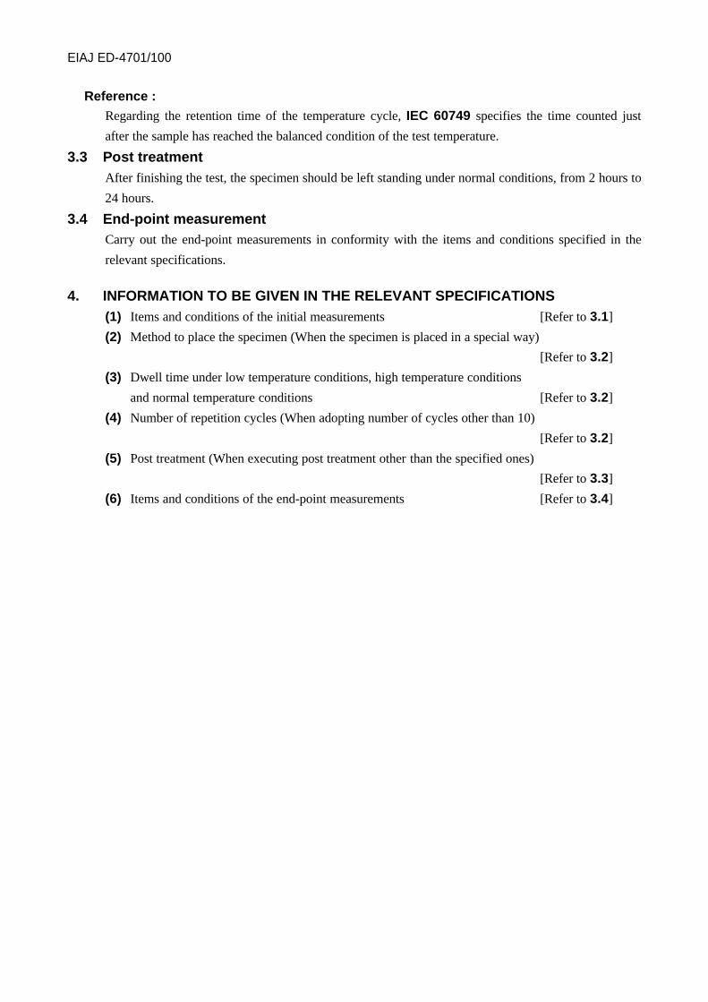
Reference :
Regarding the retention time of the temperature cycle, IEC 60749 specifies the time counted just
after the sample has reached the balanced condition of the test temperature.
3.3 Post treatmentAfter finishing the test, the specimen should be left standing under normal conditions, from 2 hours to
24 hours.
3.4 End-point measurementCarry out the end-point measurements in conformity with the items and conditions specified in the
relevant specifications.
4. INFORMATION TO BE GIVEN IN THE RELEVANT SPECIFICATIONS(1) Items and conditions of the initial measurements [Refer to 3.1]
(2) Method to place the specimen (When the specimen is placed in a special way)
[Refer to 3.2]
(3) Dwell time under low temperature conditions, high temperature conditions
and normal temperature conditions [Refer to 3.2]
(4) Number of repetition cycles (When adopting number of cycles other than 10)
[Refer to 3.2]
(5) Post treatment (When executing post treatment other than the specified ones)
[Refer to 3.3]
(6) Items and conditions of the end-point measurements [Refer to 3.4]

EIAJ ED-4701/100
REFERENCE 1 SUPPLEMENTARY INFORMATION ON THE TEST METHOD
1. Discussion contents about the revision and carried over problems.In discussing the revision based on the compatibility with IEC, questionnaires were sent to the
committee of each company for the review about the necessity of the revision of temperature cycle
test, test condition, and purposes of the test(presumable environments and failure modes),and the
following results were obtained.
(1) Necessity of the revision of temperature cycle test.
A half of the committee (9 out of 17 companies) were of the opinion that the revision is not
necessary, in particular. The opinions referring to the revision comprise the necessity of defining
the purposes of the test and recheck and review of the required number of test cycles.
(2) Test conditions.
(a) The test temperature conditions were divided roughly in to the three conditions shown below.
-65 ←→ +150°C, -55 ←→ +150°C, Tstg.min ←→ Tstg.max.
(b) Regarding the number of test cycles, the committee of companies were of the following opinion.
10 ∼ 1000cycles, number of cycles demanded by customers.
- Since the execution purposes of this test were not defined yet,the number of test cycles was
noticeably dispersed among these companies as a result, because of the mixture of the number
of test cycles for the product development processes, customers, demands, and other factors.
- It doesn't always become clear but it is the present situation that is implementing the
technical opinion of the customer number of the request cycles at the number of the
customer request cycles.
(3) The purposes of test (presumable environments and failure modes) and others.
There was a following opinion from the member of the committee.
(a) Definition of the number of test cycles including the possibilities of the acceleration
according to the actual working purposes.
(b) Definition of the basis of the temperature chage conditions in the fields and required number
of resisting cycles.
(c) Definition of the presumable failure modes of wire bonding open, Aluminum metallization
line slide, etc. and the required number of cycles.
(d) Definition of the basis of the holding time specified by the unitary mass of samples.
2. ConclusionRegarding the recheck and revision of the temperature cycle testing method, the committee of the
companies were of the same opinion the required number of cycles should be specified by defining
the purposes of the test (presumable environments, failure modes, etc.)
According to the results in paragraph 1,more than a half of the committee were of the opinion that the
revision is not necessary, in particular. Since data and materials were insufficient for discussing and
reviewing the revision due to the noticeable dispersion about the number of test cycles, indefinite
purposes of the test, indefinite basis of the number of cycles, etc., the substantial revision was
difficult ,and the revision was limited to the substantial comments only at this time. The required
number of test cycles, etc. were carried over as the problems to be reviewed in the future.
EIAJ ED-4701/100
TEST METHOD 106
INTERMITTENT OPERATING LIFE
1. SCOPEThis standard provides for the method to evaluate the endurance of semiconductor devices when they
are submitted to variable electrical and thermal stresses that occur when electrical stress is applied
cyclically in ON and OFF states.
Remarks:
Care must be taken when executing this test, because the device temperature may exceed the ambient
preset temperature and rise conspicuously due to internally dissipated heat from the device.
2. TEST EQUIPMENTEquipment to be used in this test should consist of a chamber capable to keep the specified test
temperature within the specified tolerance, the power supply capable to generate intermittently the
specified AC or DC voltages, and the board to make electrical contact to the terminals of devices
under test with socket or other mounting method, having heat..
3. PROCEDURE
3.1 Initial measurementThe initial measurements should be carried out in conformity with the items and conditions specified
in relevant specifications.
3.2 TestsThe test should be carried out by turning the totality or part of the input and the power supply
cyclically ON and OFF according to the same operating condition as the test method 101 STEADY
STATE OPERATING LIFE. The test procedure should be the same as in the steady state operating
life test, except the electrical stress application method.
(1) Test circuit
The test circuit should be in conformity with the stipulations of the relevant specifications.
(2) Ambient temperature
Unless otherwise specified, the ambient temperature should be operating temperature (Topr)
specified in the relevant specifications.
Remarks:
Care must be taken because the maximum rated junction temperature (Tjmax) may be exceeded
due to internally dissipated heat from the specimen.
(3) Method and time to turn the power ON/OFF
Unless otherwise specified, the method and time to turn the power ON/OFF should be condition
specified in the relevant specifications.
(4) Number of repetition cycles
Unless otherwise specified, the number of repetition cycles should be condition specified in the
relevant specifications.
(5) Specimen mounting method
When required, the specimen should be mounted in conformity with the method specified in the

EIAJ ED-4701/100
relevant specifications.
Remarks:
When he SMD is mounted on the test board for evaluation, the relevant conditions (substrate
material, land size, soldering method, flux cleaning, etc.) should be specified in the relevant
specifications.
3.3 Post treatmentAt the end of the test period, the specimen should be stored under normal conditions from 2 hours to
24 hours.
3.4 End-point measurementThe end-point measurements should be carried out in conformity with the items and conditions
specified in the relevant specifications.
Remarks:
Electrical end-point testing shall be completed within 48 hours of removal of bias from devices.
4. INFORMATION TO BE GIVEN IN THE RELEVANT SPECIFICATIONS(1) Items and conditions of the initial measurements [Refer to 3.1]
(2) Test circuit (Circuit, applied voltage, etc.) [Refer to 3.2(1)]
(3) Ambient temperature [Refer to 3.2(2)]
(4) Method and time to turn the power ON/OFF [Refer to 3.2(3)]
(5) Number of repetition cycles [Refer to 3.2(4)]
(6) Mounting method of the specimen (When required) [Refer to 3.2(5)]
(7) Post treatment (When executing post treatment other than the specified ones)
[Refer to 3.3]
(8) Items and conditions of the end-point measurements [Refer to 3.4]