Стандарт ASME B73.3 - 2015 (Доработка ASME …...ООО "ПромХимТех"...
53
ООО "ПромХимТех" www.promhimtech.ru Стандарт ASME B73.3 - 2015 (Доработка ASME B73.3-2003 (R2008)). Спецификация для бесшовных горизонтальных центробежных насосов с односторонним всасыванием для химических процессов. Standard ASME B73.3 - 2015 (Revision of ASME B73.3-2003 (R2008)). Specification for Sealless Horizontal End Suction Centrifugal Pump for Chemical Process.
Transcript of Стандарт ASME B73.3 - 2015 (Доработка ASME …...ООО "ПромХимТех"...
A N AM E R I C A N N AT I O N A L S TA N D A R D
ASME B73.3-2015[Revision of ASME B73.3-2003 (R2008)]
Specification for Sealless Horizontal End Suction Centrifugal Pumps for Chemical Process
ООО "ПромХимТех"www.promhimtech.ru
Стандарт ASME B73.3 - 2015 (Доработка ASME B73.3-2003 (R2008)). Спецификация для бесшовных горизонтальных центробежных насосов с односторонним всасыванием для химических процессов. Standard ASME B73.3 - 2015 (Revision of ASME B73.3-2003 (R2008)). Specification for Sealless Horizontal End Suction Centrifugal Pump for Chemical Process.
ASME B73.3-2015[Revision of ASME B73.3-2003 (R2008)]
Specification forSealless HorizontalEnd SuctionCentrifugal Pumpsfor Chemical Process
A N AM E R I C A N N AT I O N A L S TA N D A R D
Two Park Avenue • New York, NY • 1 0016 USA
Date of Issuance: December 15, 2015
This Standard will be revised when the Society approves the issuance of a new edition. There willbe no written interpretations of the requirements of th is Standard issued to this edition.
Periodically certain actions of the ASME B73 Committee may be published as Cases. Cases arepublished on the ASME Web site under the B73 Committee Page at go.asme.org/B73committee asthey are issued.
Errata to codes and standards may be posted on the ASME Web site under the Committee Pages toprovide corrections to incorrectly published items, or to correct typographical or grammatical errorsin codes and standards. Such errata shall be used on the date posted.
The B73 Committee Page can be found at go.asme.org/B73committee. There is an option availableto automatically receive an e-mail notification when errata are posted to a particular code or standard.Th is option can be found on the appropriate Committee Page after selecting “Errata” in the “PublicationInformation” section.
ASME is the registered trademark of The American Society of Mechanical Engineers.
This code or standard was developed under procedures accredited as meeting the criteria for American National
Standards. The Standards Committee that approved the code or standard was balanced to assure that individuals from
competent and concerned interests have had an opportunity to participate. The proposed code or standard was made
available for public review and comment that provides an opportunity for additional public input from industry, academia,
regulatory agencies, and the public-at-large.
ASME does not “approve,” “rate,” or “endorse” any item, construction, proprietary device, or activity.
ASME does not take any position with respect to the validity of any patent rights asserted in connection with any
items mentioned in th is document, and does not undertake to insure anyone utilizing a standard against liability for
infringement of any applicable letters patent, nor assumes any such liability. Users of a code or standard are expressly
advised that determination of the validity of any such patent rights, and the risk of infringement of such rights, is
entirely their own responsibility.
Participation by federal agency representative(s) or person(s) affiliated with industry is not to be interpreted as
government or industry endorsement of th is code or standard.
ASME accepts responsibility for only those interpretations of th is document issued in accordance with the established
ASME procedures and policies, which precludes the issuance of interpretations by individuals.
No part of th is document may be reproduced in any form,
in an electronic retrieval system or otherwise,
without the prior written permission of the publisher.
The American Society of Mechanical Engineers
Two Park Avenue, New York, NY 10016-5990
Copyright © 2015 by
THE AMERICAN SOCIETY OF MECHANICAL ENGINEERS
All rights reserved
Printed in U.S.A.
CONTENTS
Foreword . . . . . . . . . . . . . . . . . . . . . . . . . . . . . . . . . . . . . . . . . . . . . . . . . . . . . . . . . . . . . . . . . . . . . . . . . . . . . . v
Committee Roster . . . . . . . . . . . . . . . . . . . . . . . . . . . . . . . . . . . . . . . . . . . . . . . . . . . . . . . . . . . . . . . . . . . . . vi
Correspondence With the B73 Committee . . . . . . . . . . . . . . . . . . . . . . . . . . . . . . . . . . . . . . . . . . . . . . vii
1 Scope . . . . . . . . . . . . . . . . . . . . . . . . . . . . . . . . . . . . . . . . . . . . . . . . . . . . . . . . . . . . . . . . . . . . . . . . 1
2 References . . . . . . . . . . . . . . . . . . . . . . . . . . . . . . . . . . . . . . . . . . . . . . . . . . . . . . . . . . . . . . . . . . . 1
3 Alternative Designs . . . . . . . . . . . . . . . . . . . . . . . . . . . . . . . . . . . . . . . . . . . . . . . . . . . . . . . . . . . 143.1 Extended Length Pump Design . . . . . . . . . . . . . . . . . . . . . . . . . . . . . . . . . . . . . . . . . . . . . . 143.2 Close Coupled Design . . . . . . . . . . . . . . . . . . . . . . . . . . . . . . . . . . . . . . . . . . . . . . . . . . . . . . . 143.3 Alternative Design . . . . . . . . . . . . . . . . . . . . . . . . . . . . . . . . . . . . . . . . . . . . . . . . . . . . . . . . . . 14
4 Nomenclature and Definitions . . . . . . . . . . . . . . . . . . . . . . . . . . . . . . . . . . . . . . . . . . . . . . . . . 154.1 Definitions of Terms . . . . . . . . . . . . . . . . . . . . . . . . . . . . . . . . . . . . . . . . . . . . . . . . . . . . . . . . . 154.2 Additional Definitions . . . . . . . . . . . . . . . . . . . . . . . . . . . . . . . . . . . . . . . . . . . . . . . . . . . . . . . 15
5 Design and Construction Features . . . . . . . . . . . . . . . . . . . . . . . . . . . . . . . . . . . . . . . . . . . . . . 155.1 Pressure and Temperature Limits . . . . . . . . . . . . . . . . . . . . . . . . . . . . . . . . . . . . . . . . . . . . 155.2 Flanges . . . . . . . . . . . . . . . . . . . . . . . . . . . . . . . . . . . . . . . . . . . . . . . . . . . . . . . . . . . . . . . . . . . . . 165.3 Casing . . . . . . . . . . . . . . . . . . . . . . . . . . . . . . . . . . . . . . . . . . . . . . . . . . . . . . . . . . . . . . . . . . . . . . 165.4 Impeller . . . . . . . . . . . . . . . . . . . . . . . . . . . . . . . . . . . . . . . . . . . . . . . . . . . . . . . . . . . . . . . . . . . . 175.5 Internal Drive Assembly . . . . . . . . . . . . . . . . . . . . . . . . . . . . . . . . . . . . . . . . . . . . . . . . . . . . . 185.6 Containment Design . . . . . . . . . . . . . . . . . . . . . . . . . . . . . . . . . . . . . . . . . . . . . . . . . . . . . . . . . 185.7 Bearings, Lubrication, and Bearing Frame (MDP) . . . . . . . . . . . . . . . . . . . . . . . . . . . . . 205.8 Outer Magnet Assembly (MDP) . . . . . . . . . . . . . . . . . . . . . . . . . . . . . . . . . . . . . . . . . . . . . 205.9 Stator Assembly (CMP) . . . . . . . . . . . . . . . . . . . . . . . . . . . . . . . . . . . . . . . . . . . . . . . . . . . . . . 215.10 Materials of Construction . . . . . . . . . . . . . . . . . . . . . . . . . . . . . . . . . . . . . . . . . . . . . . . . . . . . 215.11 Auxiliary Piping . . . . . . . . . . . . . . . . . . . . . . . . . . . . . . . . . . . . . . . . . . . . . . . . . . . . . . . . . . . . 215.12 Corrosion Allowance . . . . . . . . . . . . . . . . . . . . . . . . . . . . . . . . . . . . . . . . . . . . . . . . . . . . . . . . 215.13 Direction of Rotation . . . . . . . . . . . . . . . . . . . . . . . . . . . . . . . . . . . . . . . . . . . . . . . . . . . . . . . . 215.14 Dimensions . . . . . . . . . . . . . . . . . . . . . . . . . . . . . . . . . . . . . . . . . . . . . . . . . . . . . . . . . . . . . . . . . 255.15 Miscellaneous Design Features . . . . . . . . . . . . . . . . . . . . . . . . . . . . . . . . . . . . . . . . . . . . . . . 255.16 Monitoring Devices . . . . . . . . . . . . . . . . . . . . . . . . . . . . . . . . . . . . . . . . . . . . . . . . . . . . . . . . . 26
6 General Information . . . . . . . . . . . . . . . . . . . . . . . . . . . . . . . . . . . . . . . . . . . . . . . . . . . . . . . . . . . 266.1 Application . . . . . . . . . . . . . . . . . . . . . . . . . . . . . . . . . . . . . . . . . . . . . . . . . . . . . . . . . . . . . . . . . 266.2 Performance Curves . . . . . . . . . . . . . . . . . . . . . . . . . . . . . . . . . . . . . . . . . . . . . . . . . . . . . . . . . 276.3 Tests and Inspections . . . . . . . . . . . . . . . . . . . . . . . . . . . . . . . . . . . . . . . . . . . . . . . . . . . . . . . . 276.4 Nameplates . . . . . . . . . . . . . . . . . . . . . . . . . . . . . . . . . . . . . . . . . . . . . . . . . . . . . . . . . . . . . . . . . 31
7 Documentation . . . . . . . . . . . . . . . . . . . . . . . . . . . . . . . . . . . . . . . . . . . . . . . . . . . . . . . . . . . . . . . 317.1 General . . . . . . . . . . . . . . . . . . . . . . . . . . . . . . . . . . . . . . . . . . . . . . . . . . . . . . . . . . . . . . . . . . . . . 317.2 Requirements . . . . . . . . . . . . . . . . . . . . . . . . . . . . . . . . . . . . . . . . . . . . . . . . . . . . . . . . . . . . . . . 317.3 Document Description . . . . . . . . . . . . . . . . . . . . . . . . . . . . . . . . . . . . . . . . . . . . . . . . . . . . . . . 317.4 Specially Requested Documentation . . . . . . . . . . . . . . . . . . . . . . . . . . . . . . . . . . . . . . . . . 35
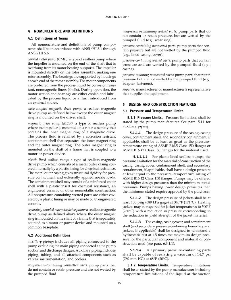
Figures5.3.5.1-1 Cooling and Heating Pipe Plans . . . . . . . . . . . . . . . . . . . . . . . . . . . . . . . . . . . . . . . . . . . . . 175.5.5.5-1 Plan 114 Modified . . . . . . . . . . . . . . . . . . . . . . . . . . . . . . . . . . . . . . . . . . . . . . . . . . . . . . . . . . . 195.16.4-1 CMP Vibration Measurement Locations . . . . . . . . . . . . . . . . . . . . . . . . . . . . . . . . . . . . . . 277.3.1-1 Pump and Driver Outline Drawing for Separately Coupled Magnetic Drive
Pumps . . . . . . . . . . . . . . . . . . . . . . . . . . . . . . . . . . . . . . . . . . . . . . . . . . . . . . . . . . . . . . . . . . . . 327.3.1-2 Pump and Driver Outline Drawing for Canned Motor Pumps . . . . . . . . . . . . . . . . 33
iii
Tables1-1 Pump Dimensions for Separately Coupled Magnetic Drive Pumps . . . . . . . . . . . . 21-2 Baseplate Dimensions for Separately Coupled Magnetic Drive Pumps . . . . . . . . 52-1 Baseplate Dimensions for Close Coupled Magnetic Drive Pumps . . . . . . . . . . . . . 73-1 Pump Dimensions for Canned Motor Pumps . . . . . . . . . . . . . . . . . . . . . . . . . . . . . . . . . 93-2 Baseplate Dimensions for Canned Motor Pumps . . . . . . . . . . . . . . . . . . . . . . . . . . . . . 115.10.1 .2-1 Magnetic Drive and Canned Motor Pump Material Classification Codes . . . . . . 225.10.1 .3-1 ASTM Material Specifications . . . . . . . . . . . . . . . . . . . . . . . . . . . . . . . . . . . . . . . . . . . . . . . . 245.11.1-1 Minimum Requirements for Auxiliary Piping Materials . . . . . . . . . . . . . . . . . . . . . . . 256.1 .5-1 Approximate Hydraulic Coverage, 50 Hz . . . . . . . . . . . . . . . . . . . . . . . . . . . . . . . . . . . . 286.1 .5-2 Approximate Hydraulic Coverage, 60 Hz . . . . . . . . . . . . . . . . . . . . . . . . . . . . . . . . . . . . 296.1 .6.1-1 Minimum Continuous Flow . . . . . . . . . . . . . . . . . . . . . . . . . . . . . . . . . . . . . . . . . . . . . . . . . 30
Mandatory AppendixI ASME Sealless Centrifugal Pump Data Sheet . . . . . . . . . . . . . . . . . . . . . . . . . . . . . . . . . 37
Nonmandatory AppendixA Electronic Data Exchange . . . . . . . . . . . . . . . . . . . . . . . . . . . . . . . . . . . . . . . . . . . . . . . . . . . . 44
iv
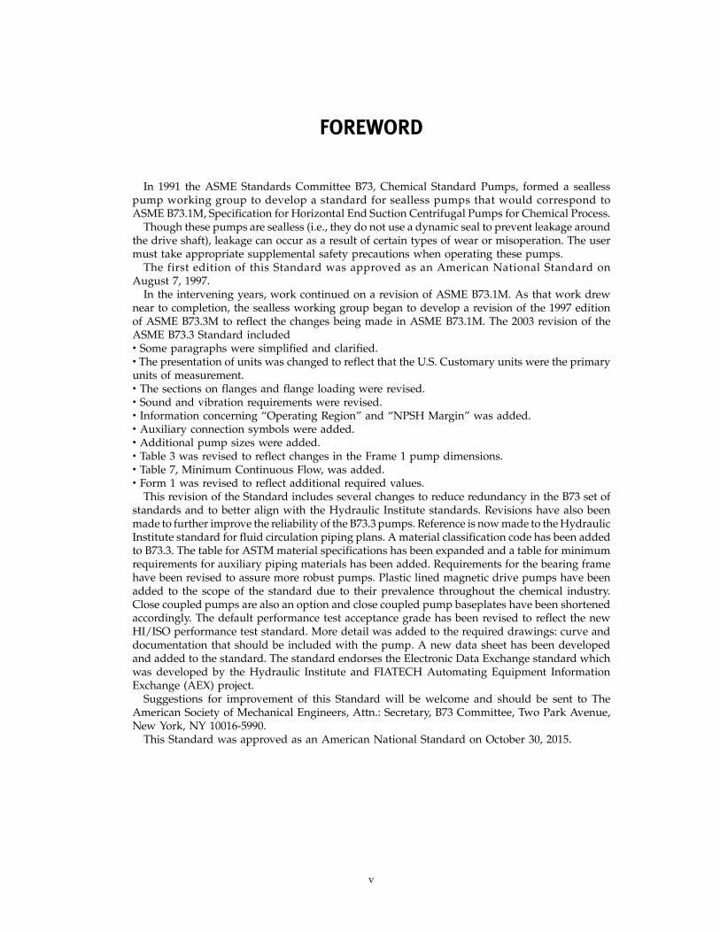
FOREWORD
In 1991 the ASME Standards Committee B73, Chemical Standard Pumps, formed a seallesspump working group to develop a standard for sealless pumps that would correspond toASME B73.1M, Specification for Horizontal End Suction Centrifugal Pumps for Chemical Process.
Though these pumps are sealless (i.e., they do not use a dynamic seal to prevent leakage aroundthe drive shaft), leakage can occur as a result of certain types of wear or misoperation. The usermust take appropriate supplemental safety precautions when operating these pumps.
The first edition of this Standard was approved as an American National Standard onAugust 7, 1997.
In the intervening years, work continued on a revision of ASME B73.1M. As that work drewnear to completion, the sealless working group began to develop a revision of the 1997 editionof ASME B73.3M to reflect the changes being made in ASME B73.1M. The 2003 revision of theASME B73.3 Standard includedW Some paragraphs were simplified and clarified.W The presentation of units was changed to reflect that the U.S. Customary units were the primaryunits of measurement.W The sections on flanges and flange loading were revised.W Sound and vibration requirements were revised.W Information concerning “Operating Region” and “NPSH Margin” was added.W Auxiliary connection symbols were added.W Additional pump sizes were added.W Table 3 was revised to reflect changes in the Frame 1 pump dimensions.W Table 7, Minimum Continuous Flow, was added.W Form 1 was revised to reflect additional required values.
This revision of the Standard includes several changes to reduce redundancy in the B73 set ofstandards and to better align with the Hydraulic Institute standards. Revisions have also beenmade to further improve the reliability of the B73.3 pumps. Reference is now made to the HydraulicInstitute standard for fluid circulation piping plans. A material classification code has been addedto B73.3. The table for ASTM material specifications has been expanded and a table for minimumrequirements for auxiliary piping materials has been added. Requirements for the bearing framehave been revised to assure more robust pumps. Plastic lined magnetic drive pumps have beenadded to the scope of the standard due to their prevalence throughout the chemical industry.Close coupled pumps are also an option and close coupled pump baseplates have been shortenedaccordingly. The default performance test acceptance grade has been revised to reflect the newHI/ISO performance test standard. More detail was added to the required drawings: curve anddocumentation that should be included with the pump. A new data sheet has been developedand added to the standard. The standard endorses the Electronic Data Exchange standard whichwas developed by the Hydraulic Institute and FIATECH Automating Equipment InformationExchange (AEX) project.
Suggestions for improvement of this Standard will be welcome and should be sent to TheAmerican Society of Mechanical Engineers, Attn.: Secretary, B73 Committee, Two Park Avenue,New York, NY 10016-5990.
This Standard was approved as an American National Standard on October 30, 2015.
v
ASME B73 COMMITTEEChemical Standard Pumps
(The following is the roster of the Committee at the time of approval of th is Standard.)
STANDARDS COMMITTEE OFFICERS
K. R. Burkhardt, ChairR. W. Estep, Vice Chair
C. J. Gomez, Secretary
STANDARDS COMMITTEE PERSONNEL
K. R. Burkhardt, DuPontD. W. Wood, Alternate, DuPontG. C. Clasby, Flowserve Corp., Flow Solutions Group
C. K. van der Sluijs, Alternate, Flowserve Corp., Flow Solutions
Group
M. Coussens, Peerless Pump Co.
J . F. Dolniak, NIPSCOR. W. Estep, The Dow Chemical Co.
C. J. Gomez, The American Society of Mechanical Engineers
vi
M. B. Huebner, Flowserve Corp.
I . S. James, Best PumpWorks
S. Jaskiewicz, Teikoku USA
B. S. Myers, Bayer CropScienceG. W. Sabol, Flint Hills Resources
B. K. Schnelzer, Met-Pro Corp., Dean Pump Division
W. W. Parry, Alternate, Met-Pro Global Pump Solutions
A. E. Stavale, ITT Goulds Pumps
E. J. Kupp, Alternate, ITT Goulds Pumps
CORRESPONDENCE WITH THE B73 COMMITTEE
General. ASME Standards are developed and maintained with the intent to represent theconsensus of concerned interests. As such, users of this Standard may interact with the Committeeby proposing revisions or a Case and attending Committee meetings. Correspondence shouldbe addressed to:
Secretary, B73 Standards CommitteeThe American Society of Mechanical EngineersTwo Park AvenueNew York, NY 10016-5990http://go.asme.org/Inquiry
Proposing Revisions. Revisions are made periodically to the Standard to incorporate changesthat appear necessary or desirable, as demonstrated by the experience gained from the applicationof the Standard. Approved revisions will be published periodically.
The Committee welcomes proposals for revisions to this Standard. Such proposals should beas specific as possible, citing the paragraph number(s), the proposed wording, and a detaileddescription of the reasons for the proposal, including any pertinent documentation.Proposing a Case. Cases may be issued for the purpose of providing alternative rules when
justified, to permit early implementation of an approved revision when the need is urgent, or toprovide rules not covered by existing provisions. Cases are effective immediately uponASME approval and shall be posted on the ASME Committee Web page.
Requests for Cases shall provide a Statement of Need and Background Information. The requestshould identify the Standard and the paragraph, figure, or table number(s), and be written as aQuestion and Reply in the same format as existing Cases. Requests for Cases should also indicatethe applicable edition(s) of the Standard to which the proposed Case applies.Attending Committee Meetings. The B73 Standards Committee regularly holds meetings
and/or telephone conferences that are open to the public. Persons wishing to attend any meetingand/or telephone conference should contact the Secretary of the B73 Standards Committee. FutureCommittee meeting dates and locations can be found on the Committee Page atgo.asme.org/B73committee.
vii

INTENTIONALLY LEFT BLANK
viii
ASME B73.3-2015
SPECIFICATION FOR SEALLESS HORIZONTAL END SUCTIONCENTRIFUGAL PUMPS FOR CHEMICAL PROCESS
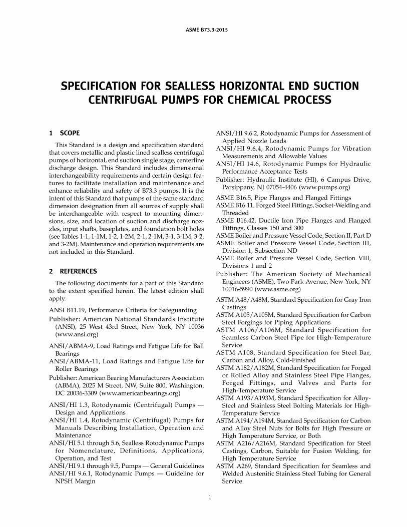
1 SCOPE
This Standard is a design and specification standardthat covers metallic and plastic lined sealless centrifugalpumps of horizontal, end suction single stage, centerlinedischarge design. This Standard includes dimensionalinterchangeability requirements and certain design fea-tures to facilitate installation and maintenance andenhance reliability and safety of B73.3 pumps. It is theintent of this Standard that pumps of the same standarddimension designation from all sources of supply shallbe interchangeable with respect to mounting dimen-sions, size, and location of suction and discharge noz-zles, input shafts, baseplates, and foundation bolt holes(see Tables 1-1, 1-1M, 1-2, 1-2M, 2-1, 2-1M, 3-1, 3-1M, 3-2,and 3-2M). Maintenance and operation requirements arenot included in this Standard.
2 REFERENCES
The following documents for a part of this Standardto the extent specified herein. The latest edition shallapply.
ANSI B11.19, Performance Criteria for Safeguarding
Publisher: American National Standards Institute(ANSI), 25 West 43rd Street, New York, NY 10036(www.ansi.org)
ANSI/ABMA-9, Load Ratings and Fatigue Life for BallBearings
ANSI/ABMA-11 , Load Ratings and Fatigue Life forRoller Bearings
Publisher: American Bearing Manufacturers Association(ABMA), 2025 M Street, NW, Suite 800, Washington,DC 20036-3309 (www.americanbearings.org)
ANSI/HI 1 .3, Rotodynamic (Centrifugal) Pumps —Design and Applications
ANSI/HI 1 .4, Rotodynamic (Centrifugal) Pumps forManuals Describing Installation, Operation andMaintenance
ANSI/HI 5.1 through 5.6, Sealless Rotodynamic Pumpsfor Nomenclature, Definit ions, Applications,Operation, and Test
ANSI/HI 9.1 through 9.5, Pumps — General GuidelinesANSI/HI 9.6.1, Rotodynamic Pumps — Guideline for
NPSH Margin
1
ANSI/HI 9.6.2, Rotodynamic Pumps for Assessment ofApplied Nozzle Loads
ANSI/ HI 9. 6. 4, Rotodynamic Pumps for VibrationMeasurements and Allowable Values
ANSI/HI 1 4. 6, Rotodynamic Pumps for HydraulicPerformance Acceptance Tests
Publisher: Hydraulic Institute (HI), 6 Campus Drive,Parsippany, NJ 07054-4406 (www.pumps.org)
ASME B16.5, Pipe Flanges and Flanged FittingsASME B16.11, Forged Steel Fittings, Socket-Welding and
ThreadedASME B16.42, Ductile Iron Pipe Flanges and Flanged
Fittings, Classes 150 and 300ASME Boiler and Pressure Vessel Code, Section II, Part DASME Boiler and Pressure Vessel Code, Section III,
Division 1, Subsection NDASME Boiler and Pressure Vessel Code, Section VIII,
Divisions 1 and 2
Publisher: The American Society of MechanicalEngineers (ASME), Two Park Avenue, New York, NY10016-5990 (www.asme.org)
ASTM A48/A48M, Standard Specification for Gray IronCastings
ASTM A105/A105M, Standard Specification for CarbonSteel Forgings for Piping Applications
ASTM A1 06/ A1 06M, Standard Specification forSeamless Carbon Steel Pipe for High-TemperatureService
ASTM A1 08, Standard Specification for Steel Bar,Carbon and Alloy, Cold-Finished
ASTM A182/A182M, Standard Specification for Forgedor Rolled Alloy and Stainless Steel Pipe Flanges,Forged Fitt ings, and Valves and Parts forHigh-Temperature Service
ASTM A193/A193M, Standard Specification for Alloy-Steel and Stainless Steel Bolting Materials for High-Temperature Service
ASTM A194/A194M, Standard Specification for Carbonand Alloy Steel Nuts for Bolts for High Pressure orHigh Temperature Service, or Both
ASTM A216/A216M, Standard Specification for SteelCastings, Carbon, Suitable for Fusion Welding, forHigh Temperature Service
ASTM A269, Standard Specification for Seamless andWelded Austenitic Stainless Steel Tubing for GeneralService
ASME B73.3-2015
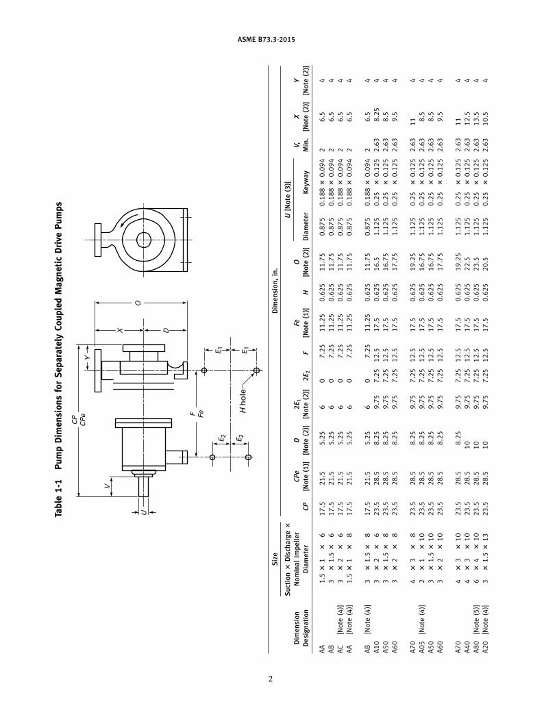
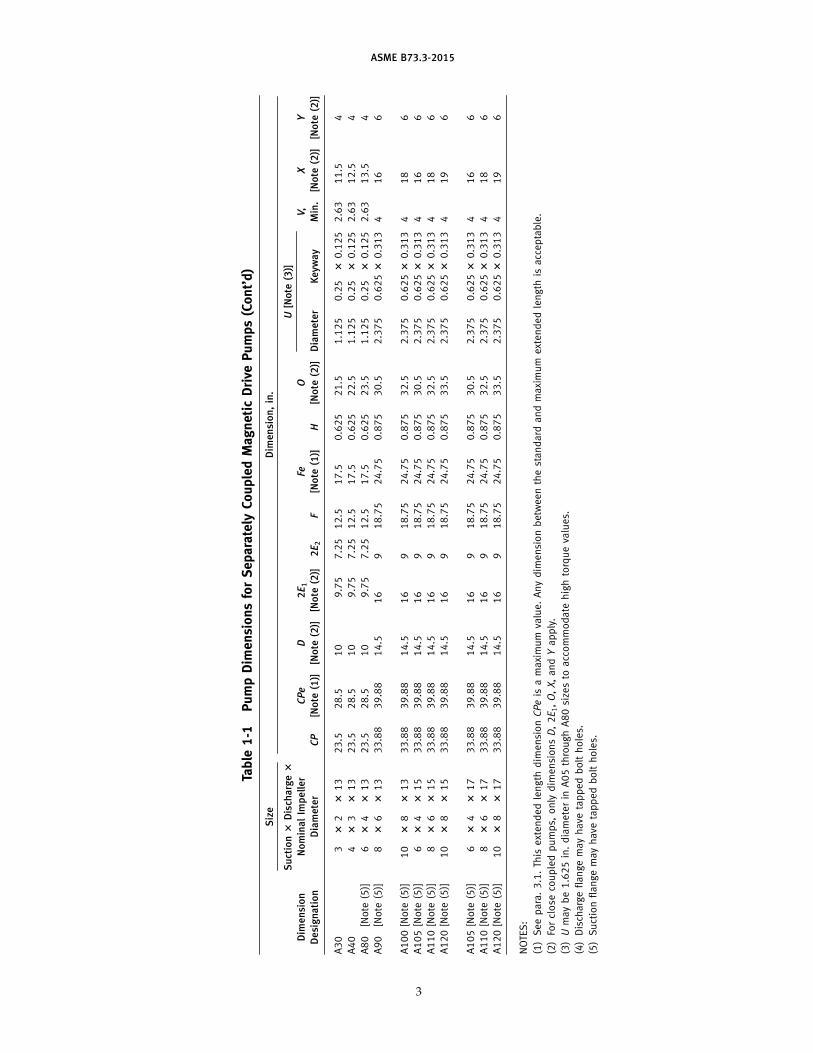
Table1-1
PumpDimensionsforSeparatelyCoupledMagneticDrivePumps
Y
X
OU
V
CP
CPe F Fe
E2
E1
E1
H hole
E2
D
Siz
eD
imen
sio
n,
in.
Su
ctio
n?
Dis
cha
rge?
U[N
ote
(3)]
Dim
en
sio
nN
om
inal
Imp
ell
er
CPe
D2E
1Fe
OV,
XY
De
sig
na
tio
nD
iam
ete
rCP
[No
te(1
)][N
ote
(2)]
[No
te(2
)]2E
2F
[No
te(1
)]H
[No
te(2
)]D
iam
ete
rK
eyw
ay
Min
.[N
ote
(2)]
[No
te(2
)]
AA
1.5?
1?
617.5
21.5
5.25
60
7.25
11.25
0.625
11.75
0.875
0.188?
0.094
26.5
4
AB
3?
1.5?
617.5
21.5
5.25
60
7.25
11.25
0.625
11.75
0.875
0.188?
0.094
26.5
4
AC
[Note
(4)]
3?
2?
617.5
21.5
5.25
60
7.25
11.25
0.625
11.75
0.875
0.188?
0.094
26.5
4
AA
[Note
(4)]
1.5?
1?
817.5
21.5
5.25
60
7.25
11.25
0.625
11.75
0.875
0.188?
0.094
26.5
4
AB
[Note
(4)]
3?
1.5?
817.5
21.5
5.25
60
7.25
11.25
0.625
11.75
0.875
0.188?
0.094
26.5
4
A10
3?
2?
623.5
28.5
8.25
9.75
7.25
12.5
17.5
0.625
16.5
1.125
0.25
?0.125
2.63
8.25
4
A50
3?
1.5?
823.5
28.5
8.25
9.75
7.25
12.5
17.5
0.625
16.75
1.125
0.25
?0.125
2.63
8.5
4
A60
3?
2?
823.5
28.5
8.25
9.75
7.25
12.5
17.5
0.625
17.75
1.125
0.25
?0.125
2.63
9.5
4
A70
4?
3?
823.5
28.5
8.25
9.75
7.25
12.5
17.5
0.625
19.25
1.125
0.25
?0.125
2.63
11
4
A05
[Note
(4)]
2?
1?
10
23.5
28.5
8.25
9.75
7.25
12.5
17.5
0.625
16.75
1.125
0.25
?0.125
2.63
8.5
4
A50
3?
1.5?
10
23.5
28.5
8.25
9.75
7.25
12.5
17.5
0.625
16.75
1.125
0.25
?0.125
2.63
8.5
4
A60
3?
2?
10
23.5
28.5
8.25
9.75
7.25
12.5
17.5
0.625
17.75
1.125
0.25
?0.125
2.63
9.5
4
A70
4?
3?
10
23.5
28.5
8.25
9.75
7.25
12.5
17.5
0.625
19.25
1.125
0.25
?0.125
2.63
11
4
A40
4?
3?
10
23.5
28.5
10
9.75
7.25
12.5
17.5
0.625
22.5
1.125
0.25
?0.125
2.63
12.5
4
A80
[Note
(5)]
6?
4?
10
23.5
28.5
10
9.75
7.25
12.5
17.5
0.625
23.5
1.125
0.25
?0.125
2.63
13.5
4
A20
[Note
(4)]
3?
1.5?
13
23.5
28.5
10
9.75
7.25
12.5
17.5
0.625
20.5
1.125
0.25
?0.125
2.63
10.5
4
2
ASME B73.3-2015
Table1-1
PumpDimensionsforSeparatelyCoupledMagneticDrivePumps(Cont’d)
Siz
eD
imen
sio
n,
in.
Su
ctio
n?
Dis
cha
rge?
U[N
ote
(3)]
Dim
en
sio
nN
om
inal
Imp
ell
er
CPe
D2E
1Fe
OV,
XY
De
sig
na
tio
nD
iam
ete
rCP
[No
te(1
)][N
ote
(2)]
[No
te(2
)]2E
2F
[No
te(1
)]H
[No
te(2
)]D
iam
ete
rK
eyw
ay
Min
.[N
ote
(2)]
[No
te(2
)]
A30
3?
2?
13
23.5
28.5
10
9.75
7.25
12.5
17.5
0.625
21.5
1.125
0.25
?0.125
2.63
11.5
4
A40
4?
3?
13
23.5
28.5
10
9.75
7.25
12.5
17.5
0.625
22.5
1.125
0.25
?0.125
2.63
12.5
4
A80
[Note
(5)]
6?
4?
13
23.5
28.5
10
9.75
7.25
12.5
17.5
0.625
23.5
1.125
0.25
?0.125
2.63
13.5
4
A90
[Note
(5)]
8?
6?
13
33.88
39.88
14.5
16
918.75
24.75
0.875
30.5
2.375
0.625?
0.313
416
6
A100
[Note
(5)]
10
?8
?13
33.88
39.88
14.5
16
918.75
24.75
0.875
32.5
2.375
0.625?
0.313
418
6
A105
[Note
(5)]
6?
4?
15
33.88
39.88
14.5
16
918.75
24.75
0.875
30.5
2.375
0.625?
0.313
416
6
A110
[Note
(5)]
8?
6?
15
33.88
39.88
14.5
16
918.75
24.75
0.875
32.5
2.375
0.625?
0.313
418
6
A120
[Note
(5)]
10
?8
?15
33.88
39.88
14.5
16
918.75
24.75
0.875
33.5
2.375
0.625?
0.313
419
6
A105
[Note
(5)]
6?
4?
17
33.88
39.88
14.5
16
918.75
24.75
0.875
30.5
2.375
0.625?
0.313
416
6
A110
[Note
(5)]
8?
6?
17
33.88
39.88
14.5
16
918.75
24.75
0.875
32.5
2.375
0.625?
0.313
418
6
A120
[Note
(5)]
10
?8
?17
33.88
39.88
14.5
16
918.75
24.75
0.875
33.5
2.375
0.625?
0.313
419
6
NOTE
S:
(1)
Seepara.3.1.Th
isextended
length
dim
ensionCPeis
amaximum
value.Anydim
ension
betw
een
thestandard
and
maximum
extended
length
isacceptable.
(2)
Forclose
coupled
pumps,
only
dim
ensionsD,2E1,O,X,andYapply.
(3)U
maybe1.625
in.diameterin
A05
through
A80
size
sto
acc
ommodate
high
torqueva
lues.
(4)
Disch
argeflange
mayhave
tapped
bolt
holes.
(5)
Suction
flangemayhave
tapped
bolt
holes.
3
ASME B73.3-2015
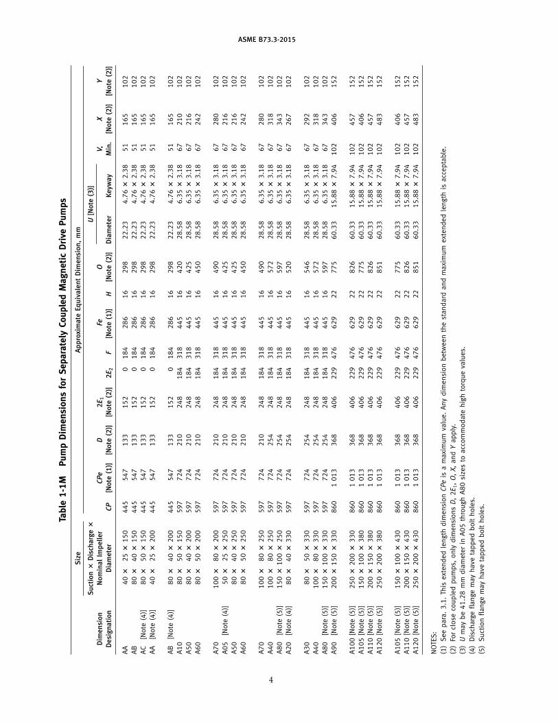
Table1-1M
PumpDimensionsforSeparatelyCoupledMagneticDrivePumps
Siz
eA
pp
roxi
ma
teEq
uiv
ale
nt
Dim
en
sio
n,
mm
Su
ctio
n?
Dis
cha
rge?
U[N
ote
(3)]
Dim
en
sio
nN
om
inal
Imp
ell
er
CPe
D2E
1Fe
OV,
XY
De
sig
na
tio
nD
iam
ete
rCP
[No
te(1
)][N
ote
(2)]
[No
te(2
)]2E
2F
[No
te(1
)]H
[No
te(2
)]D
iam
ete
rK
eyw
ay
Min
.[N
ote
(2)]
[No
te(2
)]
AA
40?
25?
150
445
547
133
152
0184
286
16
298
22.23
4.76?
2.38
51
165
102
AB
80?
40?
150
445
547
133
152
0184
286
16
298
22.23
4.76?
2.38
51
165
102
AC
[Note
(4)]
80?
50?
150
445
547
133
152
0184
286
16
298
22.23
4.76?
2.38
51
165
102
AA
[Note
(4)]
40?
25?
200
445
547
133
152
0184
286
16
298
22.23
4.76?
2.38
51
165
102
AB
[Note
(4)]
80?
40?
200
445
547
133
152
0184
286
16
298
22.23
4.76?
2.38
51
165
102
A10
80?
50?
150
597
724
210
248
184
318
445
16
420
28.58
6.35?
3.18
67
210
102
A50
80?
40?
200
597
724
210
248
184
318
445
16
425
28.58
6.35?
3.18
67
216
102
A60
80?
50?
200
597
724
210
248
184
318
445
16
450
28.58
6.35?
3.18
67
242
102
A70
100?
80?
200
597
724
210
248
184
318
445
16
490
28.58
6.35?
3.18
67
280
102
A05
[Note
(4)]
50?
25?
250
597
724
210
248
184
318
445
16
425
28.58
6.35?
3.18
67
216
102
A50
80?
40?
250
597
724
210
248
184
318
445
16
425
28.58
6.35?
3.18
67
216
102
A60
80?
50?
250
597
724
210
248
184
318
445
16
450
28.58
6.35?
3.18
67
242
102
A70
100?
80?
250
597
724
210
248
184
318
445
16
490
28.58
6.35?
3.18
67
280
102
A40
100?
80?
250
597
724
254
248
184
318
445
16
572
28.58
6.35?
3.18
67
318
102
A80
[Note
(5)]
150?
100?
250
597
724
254
248
184
318
445
16
597
28.58
6.35?
3.18
67
343
102
A20
[Note
(4)]
80?
40?
330
597
724
254
248
184
318
445
16
520
28.58
6.35?
3.18
67
267
102
A30
80?
50?
330
597
724
254
248
184
318
445
16
546
28.58
6.35?
3.18
67
292
102
A40
100?
80?
330
597
724
254
248
184
318
445
16
572
28.58
6.35?
3.18
67
318
102
A80
[Note
(5)]
150?
100?
330
597
724
254
248
184
318
445
16
597
28.58
6.35?
3.18
67
343
102
A90
[Note
(5)]
200?
150?
330
860
1013
368
406
229
476
629
22
775
60.33
15.88?
7.94
102
406
152
A100
[Note
(5)]
250?
200?
330
860
1013
368
406
229
476
629
22
826
60.33
15.88?
7.94
102
457
152
A105
[Note
(5)]
150?
100?
380
860
1013
368
406
229
476
629
22
775
60.33
15.88?
7.94
102
406
152
A110
[Note
(5)]
200?
150?
380
860
1013
368
406
229
476
629
22
826
60.33
15.88?
7.94
102
457
152
A120
[Note
(5)]
250?
200?
380
860
1013
368
406
229
476
629
22
851
60.33
15.88?
7.94
102
483
152
A105
[Note
(5)]
150?
100?
430
860
1013
368
406
229
476
629
22
775
60.33
15.88?
7.94
102
406
152
A110
[Note
(5)]
200?
150?
430
860
1013
368
406
229
476
629
22
826
60.33
15.88?
7.94
102
457
152
A120
[Note
(5)]
250?
200?
430
860
1013
368
406
229
476
629
22
851
60.33
15.88?
7.94
102
483
152
NOTE
S:
(1)Seepara.3.1.Th
isextended
length
dim
ensionCPeis
amaximum
value.Anydim
ension
betw
een
thestandard
and
maximum
extended
length
isacceptable.
(2)Fo
rclose
coupled
pumps,
only
dim
ensionsD,2E1,O,X,andYapply.
(3)U
maybe41.28
mm
diameterin
A05
through
A80
size
sto
acc
ommodate
high
torqueva
lues.
(4)Disch
argeflange
mayhave
tapped
bolt
holes.
(5)Suctionflangemayhave
tapped
bolt
holes.
4
ASME B73.3-2015
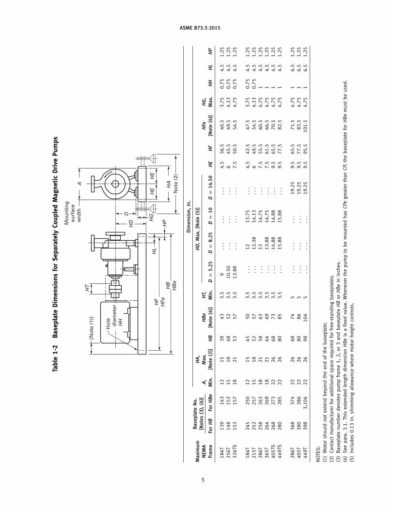
Table1-2
BaseplateDimensionsforSeparatelyCoupledMagneticDrivePumps
HGD
Mounting
surface
width
Hole
diam
eter
HH
[Note (1)]
HE
HE
HAA
HD
HT
HL
HP
HF
HFe
HB
HBe
Note (2)
Dim
en
sio
n,
in.
Base
pla
teN
o.
Ma
xim
um
HA
,HD
,M
ax.
[No
te(5
)][N
ote
s(3
),(4
)]N
EMA
A,
Ma
x.HBe
HT,
HFe
HG
,
Fra
me
ForHB
ForHBe
Min
.[N
ote
(2)]
HB
[No
te(4
)]M
in.
Dp
5.2
5Dp
8.2
5Dp
10
Dp
14
.50
HE
HF
[No
te(4
)]M
ax.
HH
HL
HP
184T
139
143
12
15
39
43
3.5
9...
...
...
4.5
36.5
40.5
3.75
0.75
4.5
1.25
256T
148
152
15
18
48
52
3.5
10.50
...
...
...
645.5
49.5
4.13
0.75
4.5
1.25
326TS
153
157
18
21
53
57
3.5
12.88
...
...
...
7.5
50.5
54.5
4.75
0.75
4.5
1.25
184T
245
250
12
15
45
50
3.5
...
12
13.75
...
4.5
42.5
47.5
3.75
0.75
4.5
1.25
215T
252
257
15
18
52
57
3.5
...
12.38
14.13
...
649.5
54.5
4.13
0.75
4.5
1.25
286T
258
263
18
21
58
63
3.5
...
13
14.75
...
7.5
55.5
60.5
4.75
14.5
1.25
365T
264
269
18
21
64
69
3.5
...
13.88
14.75
...
7.5
61.5
66.5
4.75
14.5
1.25
405TS
268
273
22
26
68
73
3.5
...
14.88
14.88
...
9.5
65.5
70.5
4.75
14.5
1.25
449TS
280
285
22
26
80
85
3.5
...
15.88
15.88
...
9.5
77.5
82.5
4.75
14.5
1.25
286T
368
374
22
26
68
74
5...
...
...
19.25
9.5
65.5
71.5
4.75
16.5
1.25
405T
380
386
22
26
80
86
5...
...
...
19.25
9.5
77.5
83.5
4.75
16.5
1.25
449T
398
3,104
22
26
98
104
5...
...
...
19.25
9.5
95.5
101.5
4.75
16.5
1.25
NOTE
S:
(1)Motorsh
ould
notextendbeyo
ndtheendofthebase
plate.
(2)Contact
manufacturerforadditionalsp
ace
required
forfree-standingbase
plates.
(3)Base
plate
numberdenotespump
frame1,2,or3
and
base
plate
HB
orHBein
inch
es.
(4)Seepara.3.1.Th
isextended
length
dim
ensionHBeis
afixe
dva
lue.Wheneve
rthepumpto
bemountedhasCPegreaterthanCP,
thebase
plate
forHBemust
beuse
d.
(5)Includes0.13in.sh
immingallowance
where
motorheightco
ntrols.
5
ASME B73.3-2015
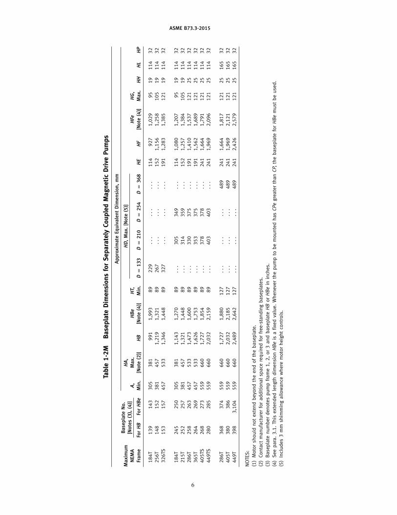
Table1-2M
BaseplateDimensionsforSeparatelyCoupledMagneticDrivePumps
Ap
pro
xim
ate
Equ
iva
len
tD
ime
nsi
on
,m
m
Base
pla
teN
o.
Ma
xim
um
HA
,HD
,M
ax.
[No
te(5
)][N
ote
s(3
),(4
)]N
EM
AA
,M
ax.
HBe
HT,
HFe
HG
,
Fra
me
ForHB
ForHBe
Min
.[N
ote
(2)]
HB
[No
te(4
)]M
in.
Dp
13
3Dp
21
0Dp
25
4Dp
36
8HE
HF
[No
te(4
)]M
ax.
HH
HL
HP
184T
139
143
305
381
991
1,993
89
229
...
...
...
114
927
1,029
95
19
114
32
256T
148
152
381
457
1,219
1,321
89
267
...
...
...
152
1,156
1,258
105
19
114
32
326TS
153
157
457
533
1,346
1,448
89
327
...
...
...
191
1,283
1,385
121
19
114
32
184T
245
250
305
381
1,143
1,270
89
...
305
349
...
114
1,080
1,207
95
19
114
32
215T
252
257
381
457
1,321
1,448
89
...
314
359
...
152
1,257
1,384
105
19
114
32
286T
258
263
457
533
1,473
1,600
89
...
330
375
...
191
1,410
1,537
121
25
114
32
365T
264
269
457
533
1,626
1,753
89
...
353
375
...
191
1,562
1,689
121
25
114
32
405TS
268
273
559
660
1,727
1,854
89
...
378
378
...
241
1,664
1,791
121
25
114
32
449TS
280
285
559
660
2,032
2,159
89
...
403
403
...
241
1,969
2,096
121
25
114
32
286T
368
374
559
660
1,727
1,880
127
...
...
...
489
241
1,664
1,817
121
25
165
32
405T
380
386
559
660
2,032
2,185
127
...
...
...
489
241
1,969
2,121
121
25
165
32
449T
398
3,104
559
660
2,489
2,642
127
...
...
...
489
241
2,426
2,579
121
25
165
32
NOTE
S:
(1)Motorsh
ould
notextend
beyo
nd
theend
ofthebase
plate.
(2)Contact
manufacturerforadditionalsp
ace
required
forfree-standingbase
plates.
(3)Base
plate
numberdenotespump
frame1,2,or3
and
base
plate
HB
orHBein
inch
es.
(4)Seepara.3.1.Th
isextendedlength
dim
ensionHBeis
afixe
dva
lue.Wheneve
rthepump
tobemounted
hasCPegreaterthanCP,
thebase
plate
forHBemust
beuse
d.
(5)Includes3
mm
shim
mingallowance
where
motorheightco
ntrols.
6
ASME B73.3-2015
Table2-1
BaseplateDimensionsforCloseCoupledMagneticDrivePumps
Note (1)
HD
HP
HF
HFe
HB
HBe
Hole diameter
HH
HL
Note (2)
Mounting
surface
width A
HE
HE
HA
D
HG
Dim
en
sio
n,
in.
Base
pla
teN
o.
Ma
xim
um
HA
,HD
,M
ax.
[No
te(6
)][N
ote
s(3
),(4
),(5
)]N
EMA
A,
Ma
x.HB
HBe
HF
HFe
HG
,
Fra
me
ForHB
ForHBe
Min
.[N
ote
(2)]
[No
te(5
)][N
ote
s(4
),(5
)]Dp
5.2
5Dp
8.2
5Dp
10
HE
[No
te(5
)][N
ote
s(4
),(5
)]M
ax.
HH
HL
HP
182-184TC
132
136
12
15
32
36
9...
...
4.5
29.5
33.5
3.75
0.75
4.5
1.25
254-256TC
141
145
15
18
41
45
10.50
...
...
638.5
42.5
4.13
0.75
4.5
1.25
284-286TC/TSC
144
148
18
21
44
48
12.88
...
...
7.5
41.5
45.5
4.75
0.75
4.5
1.25
182-184TC
234
239
12
15
34
39
...
12
13.75
4.5
31.5
36.5
3.75
0.75
4.5
1.25
213-215TC
238
243
15
18
38
43
...
12.38
14.13
635.5
40.5
4.13
0.75
4.5
1.25
284-286TC/TSC
246
251
18
21
46
51
...
13
14.75
7.5
43.5
48.5
4.75
14.5
1.25
324-326TC/TSC
248
253
18
21
48
53
...
13.88
14.75
7.5
43.5
50.5
4.75
14.5
1.25
364-365TSC
248
253
18
21
48
53
...
13.88
14.75
7.5
45.5
50.5
4.75
14.5
1.25
404-405TSC
252
257
22
26
52
57
...
14.88
14.88
9.5
49.5
54.5
4.75
14.5
1.25
NOTES:
(1)Motorshould
notextendbeyondtheendofthebaseplate.
(2)Contact
manufacturerforadditionalspace
requiredforfree-standingbaseplates.
(3)Baseplate
numberdenotespumpframe1or2andbaseplate
HBorHBein
inches.
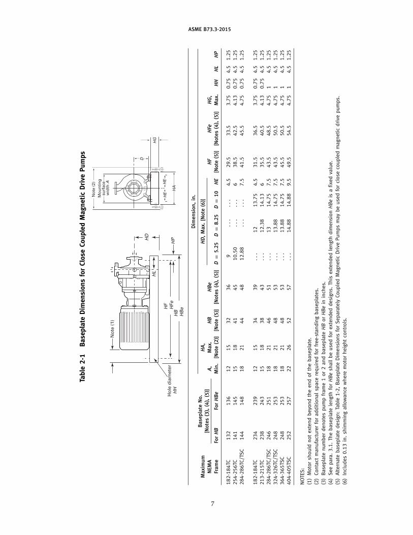
(4)Seepara.3.1.Thebaseplate
length
forHBeshallbeusedforextendeddesigns.
This
extendedlength
dim
ensionHBeis
afixedvalue.
(5)Alternate
baseplate
design:Table
1-2,Baseplate
Dim
ensionsforSeparately
CoupledMagneticDrive
Pumpsmaybeusedforclose
coupledmagneticdrive
pumps.
(6)Includes0.13in.shim
mingallowance
where
motorheightcontrols.
7
ASME B73.3-2015
Table2-1M
BaseplateDimensionsforCloseCoupledMagneticDrivePumps
Ap
pro
xim
ate
Equ
iva
len
tD
ime
nsi
on
,m
m
Base
pla
teN
o.
Ma
xim
um
HA
,HD
,M
ax.
[No
te(6
)][N
ote
s(3
),(4
),(5
)]N
EM
AA
,M
ax.
HB
HBe
HF
HFe
HG
,
Fra
me
ForHB
ForHBe
Min
.[N
ote
(2)]
[No
te(5
)][N
ote
s(4
),(5
)]Dp
13
3Dp
21
0Dp
25
4HE
[No
te(5
)][N
ote
s(4
),(5
)]M
ax.
HH
HL
HP
182-184TC
132
141
305
381
813
914
229
...
...
114
749
850
95
19
114
32
254-256TC
141
145
381
457
1041
1143
267
...
...
152
977
1079
105
19
114
32
284-286TC/TSC
144
148
457
533
1118
1219
327
...
...
191
1054
1155
121
19
114
32
182-184TC
234
239
305
381
864
991
...
305
349
114
800
927
95
19
114
32
213-215TC
238
243
381
457
965
1092
...
314
359
152
901
1028
105
19
114
32
284-286TC/TSC
246
251
457
533
1168
1295
...
330
375
191
1104
1231
121
25
114
32
324-326TC/TSC
248
253
457
533
1219
1346
...
353
375
191
1155
1282
121
25
114
32
364-365TSC
248
253
457
533
1219
1346
...
353
375
191
1155
1282
121
25
114
32
404-405TSC
252
257
559
660
1321
1448
...
378
378
241
1257
1384
121
25
114
32
NOTES:
(1)Motorshould
notextendbeyondtheendofthebaseplate.
(2)Contact
manufacturerforadditionalspace
requiredforfree-standingbaseplates.
(3)Baseplate
numberdenotespumpframe1or2andbaseplate
HBorHBein
millimeters.
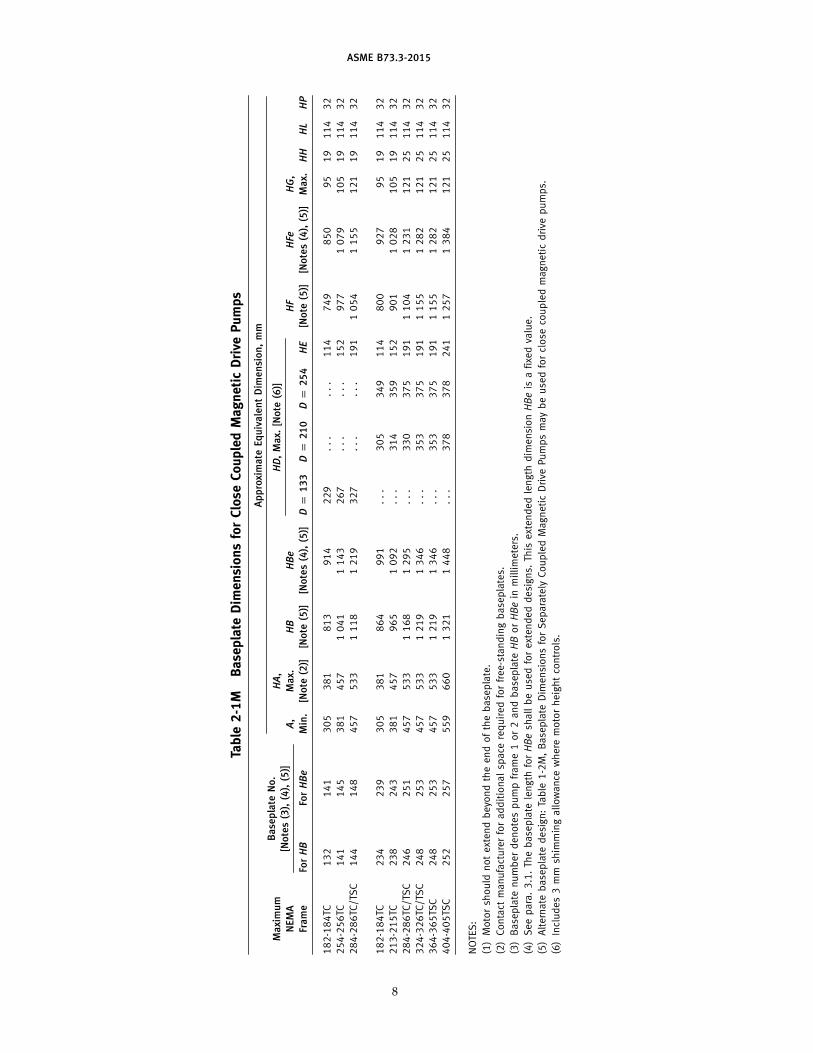
(4)Seepara.3.1.Thebaseplate
length
forHBeshallbeusedforextendeddesigns.
This
extendedlength
dim
ensionHBeis
afixedvalue.
(5)Alternate
baseplate
design:Table
1-2M,Baseplate
Dim
ensionsforSeparately
CoupledMagneticDrive
Pumpsmaybeusedforclose
coupledmagneticdrive
pumps.
(6)Includes3mm
shim
mingallowance
where
motorheightcontrols.
8
ASME B73.3-2015
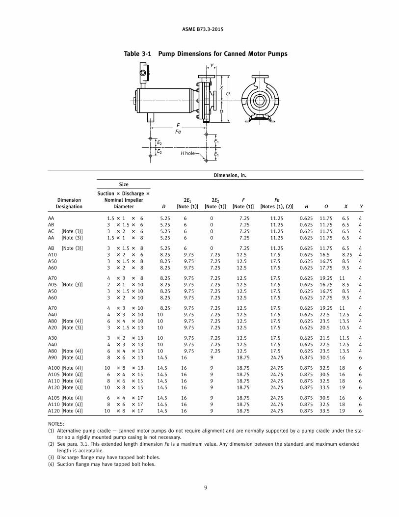
Table 3-1 Pump Dimensions for Canned Motor Pumps
H hole
O
X
Y
F
Fe
D
E1
E1
E2
E2
Dimension, in.
Size
Suction ? Discharge ?
Dimension Nominal Impeller 2E1 2E2 F Fe
Designation Diameter D [Note (1 )] [Note (1 )] [Note (1 )] [Notes (1 ), (2)] H O X Y
AA 1 .5 ? 1 ? 6 5.25 6 0 7.25 11 .25 0.625 11 .75 6.5 4
AB 3 ? 1 .5 ? 6 5.25 6 0 7.25 11 .25 0.625 11 .75 6.5 4
AC [Note (3) ] 3 ? 2 ? 6 5.25 6 0 7.25 11 .25 0.625 11 .75 6.5 4
AA [Note (3) ] 1 .5 ? 1 ? 8 5.25 6 0 7.25 11 .25 0.625 11 .75 6.5 4
AB [Note (3) ] 3 ? 1 .5 ? 8 5.25 6 0 7.25 11 .25 0.625 11 .75 6.5 4
A10 3 ? 2 ? 6 8.25 9.75 7.25 12.5 17.5 0.625 16.5 8.25 4
A50 3 ? 1 .5 ? 8 8.25 9.75 7.25 12.5 17.5 0.625 16.75 8.5 4
A60 3 ? 2 ? 8 8.25 9.75 7.25 12.5 17.5 0.625 17.75 9.5 4
A70 4 ? 3 ? 8 8.25 9.75 7.25 12.5 17.5 0.625 19.25 11 4
A05 [Note (3) ] 2 ? 1 ? 10 8.25 9.75 7.25 12.5 17.5 0.625 16.75 8.5 4
A50 3 ? 1 .5 ? 10 8.25 9.75 7.25 12.5 17.5 0.625 16.75 8.5 4
A60 3 ? 2 ? 10 8.25 9.75 7.25 12.5 17.5 0.625 17.75 9.5 4
A70 4 ? 3 ? 10 8.25 9.75 7.25 12.5 17.5 0.625 19.25 11 4
A40 4 ? 3 ? 10 10 9.75 7.25 12.5 17.5 0.625 22.5 12.5 4
A80 [Note (4) ] 6 ? 4 ? 10 10 9.75 7.25 12.5 17.5 0.625 23.5 13.5 4
A20 [Note (3) ] 3 ? 1 .5 ? 13 10 9.75 7.25 12.5 17.5 0.625 20.5 10.5 4
A30 3 ? 2 ? 13 10 9.75 7.25 12.5 17.5 0.625 21 .5 11 .5 4
A40 4 ? 3 ? 13 10 9.75 7.25 12.5 17.5 0.625 22.5 12.5 4
A80 [Note (4) ] 6 ? 4 ? 13 10 9.75 7.25 12.5 17.5 0.625 23.5 13.5 4
A90 [Note (4) ] 8 ? 6 ? 13 14.5 16 9 18.75 24.75 0.875 30.5 16 6
A100 [Note (4) ] 10 ? 8 ? 13 14.5 16 9 18.75 24.75 0.875 32.5 18 6
A105 [Note (4) ] 6 ? 4 ? 15 14.5 16 9 18.75 24.75 0.875 30.5 16 6
A110 [Note (4) ] 8 ? 6 ? 15 14.5 16 9 18.75 24.75 0.875 32.5 18 6
A120 [Note (4) ] 10 ? 8 ? 15 14.5 16 9 18.75 24.75 0.875 33.5 19 6
A105 [Note (4) ] 6 ? 4 ? 17 14.5 16 9 18.75 24.75 0.875 30.5 16 6
A110 [Note (4) ] 8 ? 6 ? 17 14.5 16 9 18.75 24.75 0.875 32.5 18 6
A120 [Note (4) ] 10 ? 8 ? 17 14.5 16 9 18.75 24.75 0.875 33.5 19 6
NOTES:
(1 ) Alternative pump cradle — canned motor pumps do not require alignment and are normally supported by a pump cradle under the sta-
tor so a rigidly mounted pump casing is not necessary.
(2) See para. 3.1 . This extended length dimension Fe is a maximum value. Any dimension between the standard and maximum extended
length is acceptable.
(3) Discharge flange may have tapped bolt holes.
(4) Suction flange may have tapped bolt holes.
9
ASME B73.3-2015
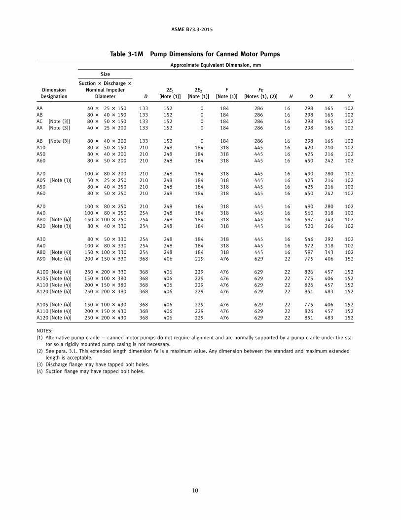
Table 3-1M Pump Dimensions for Canned Motor Pumps
Approximate Equivalent Dimension, mm
Size
Suction ? Discharge ?
Dimension Nominal Impeller 2E1 2E2 F Fe
Designation Diameter D [Note (1 )] [Note (1 )] [Note (1 )] [Notes (1 ), (2)] H O X Y
AA 40 ? 25 ? 150 133 152 0 184 286 16 298 165 102
AB 80 ? 40 ? 150 133 152 0 184 286 16 298 165 102
AC [Note (3) ] 80 ? 50 ? 150 133 152 0 184 286 16 298 165 102
AA [Note (3) ] 40 ? 25 ? 200 133 152 0 184 286 16 298 165 102
AB [Note (3) ] 80 ? 40 ? 200 133 152 0 184 286 16 298 165 102
A10 80 ? 50 ? 150 210 248 184 318 445 16 420 210 102
A50 80 ? 40 ? 200 210 248 184 318 445 16 425 216 102
A60 80 ? 50 ? 200 210 248 184 318 445 16 450 242 102
A70 100 ? 80 ? 200 210 248 184 318 445 16 490 280 102
A05 [Note (3) ] 50 ? 25 ? 250 210 248 184 318 445 16 425 216 102
A50 80 ? 40 ? 250 210 248 184 318 445 16 425 216 102
A60 80 ? 50 ? 250 210 248 184 318 445 16 450 242 102
A70 100 ? 80 ? 250 210 248 184 318 445 16 490 280 102
A40 100 ? 80 ? 250 254 248 184 318 445 16 560 318 102
A80 [Note (4) ] 150 ? 100 ? 250 254 248 184 318 445 16 597 343 102
A20 [Note (3) ] 80 ? 40 ? 330 254 248 184 318 445 16 520 266 102
A30 80 ? 50 ? 330 254 248 184 318 445 16 546 292 102
A40 100 ? 80 ? 330 254 248 184 318 445 16 572 318 102
A80 [Note (4) ] 150 ? 100 ? 330 254 248 184 318 445 16 597 343 102
A90 [Note (4) ] 200 ? 150 ? 330 368 406 229 476 629 22 775 406 152
A100 [Note (4) ] 250 ? 200 ? 330 368 406 229 476 629 22 826 457 152
A105 [Note (4) ] 150 ? 100 ? 380 368 406 229 476 629 22 775 406 152
A110 [Note (4) ] 200 ? 150 ? 380 368 406 229 476 629 22 826 457 152
A120 [Note (4) ] 250 ? 200 ? 380 368 406 229 476 629 22 851 483 152
A105 [Note (4) ] 150 ? 100 ? 430 368 406 229 476 629 22 775 406 152
A110 [Note (4) ] 200 ? 150 ? 430 368 406 229 476 629 22 826 457 152
A120 [Note (4) ] 250 ? 200 ? 430 368 406 229 476 629 22 851 483 152
NOTES:
(1 ) Alternative pump cradle — canned motor pumps do not require alignment and are normally supported by a pump cradle under the sta-
tor so a rigidly mounted pump casing is not necessary.
(2) See para. 3.1 . This extended length dimension Fe is a maximum value. Any dimension between the standard and maximum extended
length is acceptable.
(3) Discharge flange may have tapped bolt holes.
(4) Suction flange may have tapped bolt holes.
10
ASME B73.3-2015
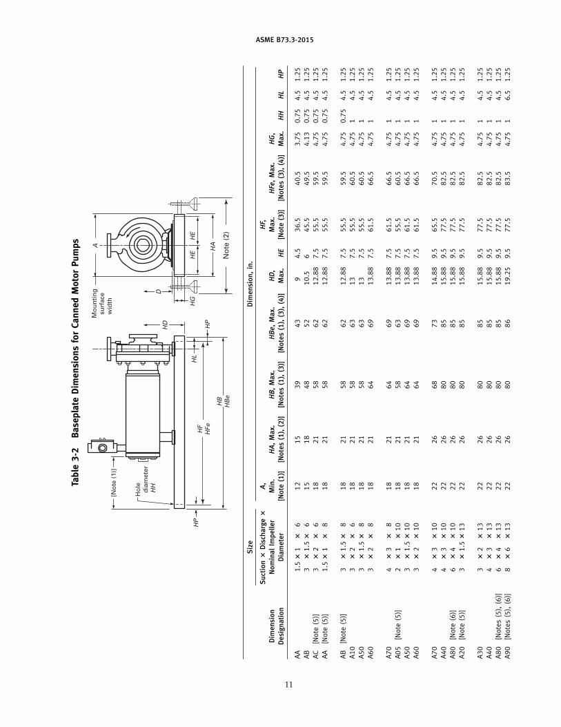
Table3-2
BaseplateDimensionsforCannedMotorPumps
HG
D
Hole
diameter
HH
[Note (1)]
HD
HL
HP
HB
HBe
HF
HFe
HP
Mounting
surface
width
HE
HE
HAA
Note (2)
Siz
eD
imen
sio
n,
in.
Su
ctio
n?
Dis
cha
rge?
A,
HF,
Dim
en
sio
nN
om
inal
Imp
ell
er
Min
.HA
,M
ax.
HB
,M
ax.
HBe
,M
ax.
HD
,M
ax.
HFe,
Ma
x.HG
,
De
sig
na
tio
nD
iam
ete
r[N
ote
(1)]
[No
tes
(1),
(2)]
[No
tes
(1),
(3)]
[No
tes
(1),
(3),
(4)]
Ma
x.HE
[No
te(3
)][N
ote
s(3
),(4
)]M
ax.
HH
HL
HP
AA
1.5?
1?
612
15
39
43
94.5
36.5
40.5
3.75
0.75
4.5
1.25
AB
3?
1.5?
615
18
48
52
10.5
645.5
49.5
4.13
0.75
4.5
1.25
AC
[Note
(5)]
3?
2?
618
21
58
62
12.88
7.5
55.5
59.5
4.75
0.75
4.5
1.25
AA
[Note
(5)]
1.5?
1?
818
21
58
62
12.88
7.5
55.5
59.5
4.75
0.75
4.5
1.25
AB
[Note
(5)]
3?
1.5?
818
21
58
62
12.88
7.5
55.5
59.5
4.75
0.75
4.5
1.25
A10
3?
2?
618
21
58
63
13
7.5
55.5
60.5
4.75
14.5
1.25
A50
3?
1.5?
818
21
58
63
13
7.5
55.5
60.5
4.75
14.5
1.25
A60
3?
2?
818
21
64
69
13.88
7.5
61.5
66.5
4.75
14.5
1.25
A70
4?
3?
818
21
64
69
13.88
7.5
61.5
66.5
4.75
14.5
1.25
A05
[Note
(5)]
2?
1?
10
18
21
58
63
13.88
7.5
55.5
60.5
4.75
14.5
1.25
A50
3?
1.5?
10
18
21
64
69
13.88
7.5
61.5
66.5
4.75
14.5
1.25
A60
3?
2?
10
18
21
64
69
13.88
7.5
61.5
66.5
4.75
14.5
1.25
A70
4?
3?
10
22
26
68
73
14.88
9.5
65.5
70.5
4.75
14.5
1.25
A40
4?
3?
10
22
26
80
85
15.88
9.5
77.5
82.5
4.75
14.5
1.25
A80
[Note
(6)]
6?
4?
10
22
26
80
85
15.88
9.5
77.5
82.5
4.75
14.5
1.25
A20
[Note
(5)]
3?
1.5?
13
22
26
80
85
15.88
9.5
77.5
82.5
4.75
14.5
1.25
A30
3?
2?
13
22
26
80
85
15.88
9.5
77.5
82.5
4.75
14.5
1.25
A40
4?
3?
13
22
26
80
85
15.88
9.5
77.5
82.5
4.75
14.5
1.25
A80
[Notes(5
),(6
)]6
?4
?13
22
26
80
85
15.88
9.5
77.5
82.5
4.75
14.5
1.25
A90
[Notes(5
),(6
)]8
?6
?13
22
26
80
86
19.25
9.5
77.5
83.5
4.75
16.5
1.25
11
ASME B73.3-2015
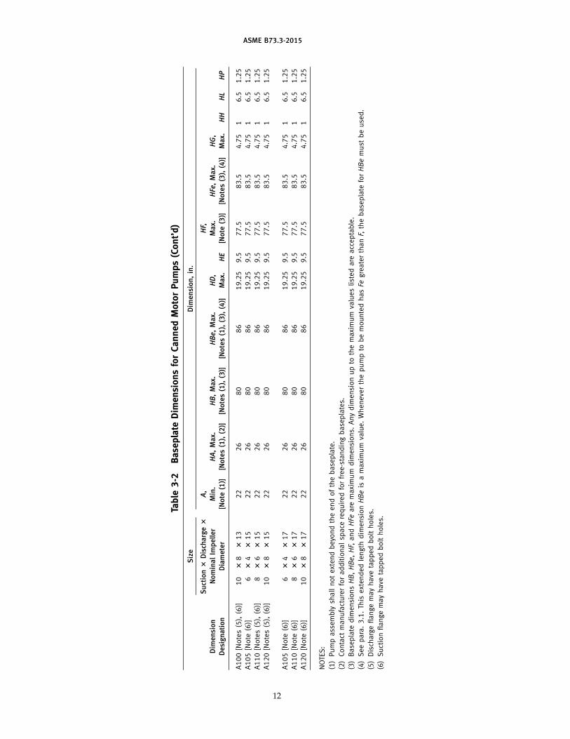
Table3-2
BaseplateDimensionsforCannedMotorPumps(Cont’d)
Siz
eD
imen
sio
n,
in.
Su
ctio
n?
Dis
cha
rge?
A,
HF,
Dim
en
sio
nN
om
inal
Imp
ell
er
Min
.HA
,M
ax.
HB
,M
ax.
HBe
,M
ax.
HD
,M
ax.
HFe,
Ma
x.HG
,
De
sig
na
tio
nD
iam
ete
r[N
ote
(1)]
[No
tes
(1),
(2)]
[No
tes
(1),
(3)]
[No
tes
(1),
(3),
(4)]
Ma
x.HE
[No
te(3
)][N
ote
s(3
),(4
)]M
ax.
HH
HL
HP
A100[Notes(5),(6)]
10
?8
?13
22
26
80
86
19.25
9.5
77.5
83.5
4.75
16.5
1.25
A105[Note
(6)]
6?
4?
15
22
26
80
86
19.25
9.5
77.5
83.5
4.75
16.5
1.25
A110[Notes(5),(6)]
8?
6?
15
22
26
80
86
19.25
9.5
77.5
83.5
4.75
16.5
1.25
A120[Notes(5),(6)]
10
?8
?15
22
26
80
86
19.25
9.5
77.5
83.5
4.75
16.5
1.25
A105[Note
(6)]
6?
4?
17
22
26
80
86
19.25
9.5
77.5
83.5
4.75
16.5
1.25
A110[Note
(6)]
8?
6?
17
22
26
80
86
19.25
9.5
77.5
83.5
4.75
16.5
1.25
A120[Note
(6)]
10
?8
?17
22
26
80
86
19.25
9.5
77.5
83.5
4.75
16.5
1.25
NOTES:
(1)Pumpassembly
shallnotextendbeyondtheendofthebaseplate.
(2)Contact
manufacturerforadditionalspace
requiredforfree-standingbaseplates.
(3)Baseplate
dim
ensionsHB,HBe,HF,andHFe
are
maximum
dim
ensions.
Anydim
ensionupto
themaximum
valueslistedare
acceptable.
(4)Seepara.3.1.This
extendedlength
dim
ensionHBeis
amaximum
value.Wheneverthepumpto
bemountedhasFe
greaterthanF,thebaseplate
forHBemust
beused.
(5)Dischargeflangemayhave
tappedboltholes.
(6)Suctionflangemayhave
tappedboltholes.
12
ASME B73.3-2015
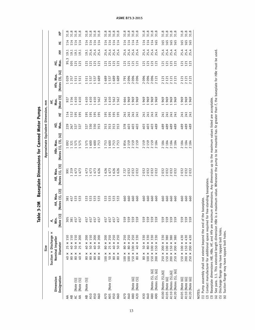
Table3-2M
BaseplateDimensionsforCannedMotorPumps
Siz
eA
pp
roxi
ma
teEq
uiv
ale
nt
Dim
en
sio
n,
mm
Su
ctio
n?
Dis
cha
rge?
A,
HF,
Dim
en
sio
nN
om
inal
Imp
ell
er
Min
.HA
,M
ax.
HB
,M
ax.
HBe
,M
ax.
HD
,M
ax.
HFe,
Ma
x.HG
,
De
sig
na
tio
nD
iam
ete
r[N
ote
(1)]
[No
tes
(1),
(2)]
[No
tes
(1),
(3)]
[No
tes
(1),
(3),
(4)]
Ma
x.HE
[No
te(3
)][N
ote
s(3
),(4
)]M
ax.
HH
HL
HP
AA
40?
25?
150
305
381
991
1092
229
114
927
1029
95.3
19.1
114
31.8
AB
80?
40?
150
381
457
1219
1321
267
152
1156
1257
105
19.1
114
31.8
AC
[Note
(5)]
80?
50?
150
457
533
1473
1575
327
191
1410
1511
121
19.1
114
31.8
AA
[Note
(5)]
40?
25?
200
457
533
1473
1575
327
191
1410
1511
121
19.1
114
31.8
AB
[Note
(5)]
80?
40?
200
457
533
1473
1575
327
191
1410
1511
121
19.1
114
31.8
A10
80?
50?
150
457
533
1473
1600
330
191
1410
1537
121
25.4
114
31.8
A50
80?
40?
200
457
533
1473
1600
330
191
1410
1537
121
25.4
114
31.8
A60
80?
50?
200
457
533
1626
1753
353
191
1562
1689
121
25.4
114
31.8
A70
100?
80?
200
457
533
1626
1753
353
191
1562
1689
121
25.4
114
31.8
A05
[Note
(5)]
50?
25?
250
457
533
1473
1600
353
191
1410
1537
121
25.4
114
31.8
A50
80?
40?
250
457
533
1626
1753
353
191
1562
1689
121
25.4
114
31.8
A60
80?
50?
250
457
533
1626
1753
353
191
1562
1689
121
25.4
114
31.8
A70
100?
80?
250
559
660
1727
1854
378
241
1664
1791
121
25.4
114
31.8
A40
100?
80?
250
559
660
2032
2159
403
241
1969
2096
121
25.4
114
31.8
A80
[Note
(6)]
150?
100?
250
559
660
2032
2159
403
241
1969
2096
121
25.4
114
31.8
A20
[Note
(5)]
80?
40?
330
559
660
2032
2159
403
241
1969
2096
121
25.4
114
31.8
A30
80?
50?
330
559
660
2032
2159
403
241
1969
2096
121
25.4
114
31.8
A40
100?
80?
330
559
660
2032
2159
403
241
1969
2096
121
25.4
114
31.8
A80
[Notes(5),(6)]
150?
100?
330
559
660
2032
2159
403
241
1969
2096
121
25.4
114
31.8
A90
[Notes(5),(6)]
200?
150?
330
559
660
2032
2184
489
241
1969
2121
121
25.4
165
31.8
A100[Notes(5),(6)]
250?
200?
330
559
660
2032
2184
489
241
1969
2121
121
25.4
165
31.8
A105[Note
(6)]
150?
100?
380
559
660
2032
2184
489
241
1969
2121
121
25.4
165
31.8
A110[Notes(5),(6)]
200?
150?
380
559
660
2032
2184
489
241
1969
2121
121
25.4
165
31.8
A120[Notes(5),(6)]
250?
200?
380
559
660
2032
2184
489
241
1969
2121
121
25.4
165
31.8
A105[Note
(6)]
150?
100?
430
559
660
2032
2184
489
241
1969
2121
121
25.4
165
31.8
A110[Note
(6)]
200?
150?
430
559
660
2032
2184
489
241
1969
2121
121
25.4
165
31.8
A120[Note
(6)]
250?
200?
430
559
660
2032
2184
489
241
1969
2121
121
25.4
165
31.8
NOTES:
(1)Pumpassembly
shallnotextendbeyondtheendofthebaseplate.
(2)Contact
manufacturerforadditionalspace
requiredforfree-standingbaseplates.
(3)Baseplate
dim
ensionsHB,HBe,HF,andHFe
are
maximum
dim
ensions.
Anydim
ensionupto
themaximum
valueslistedare
acceptable.
(4)Seepara.3.1.This
extendedlength
dim
ensionHBeis
amaximum
value.Wheneverthepumpto
bemountedhasFe
greaterthanF,thebaseplate
forHBemust
beused.
(5)Dischargeflangemayhave
tappedboltholes.
(6)Suctionflangemayhave
tappedboltholes.
13
ASME B73.3-2015
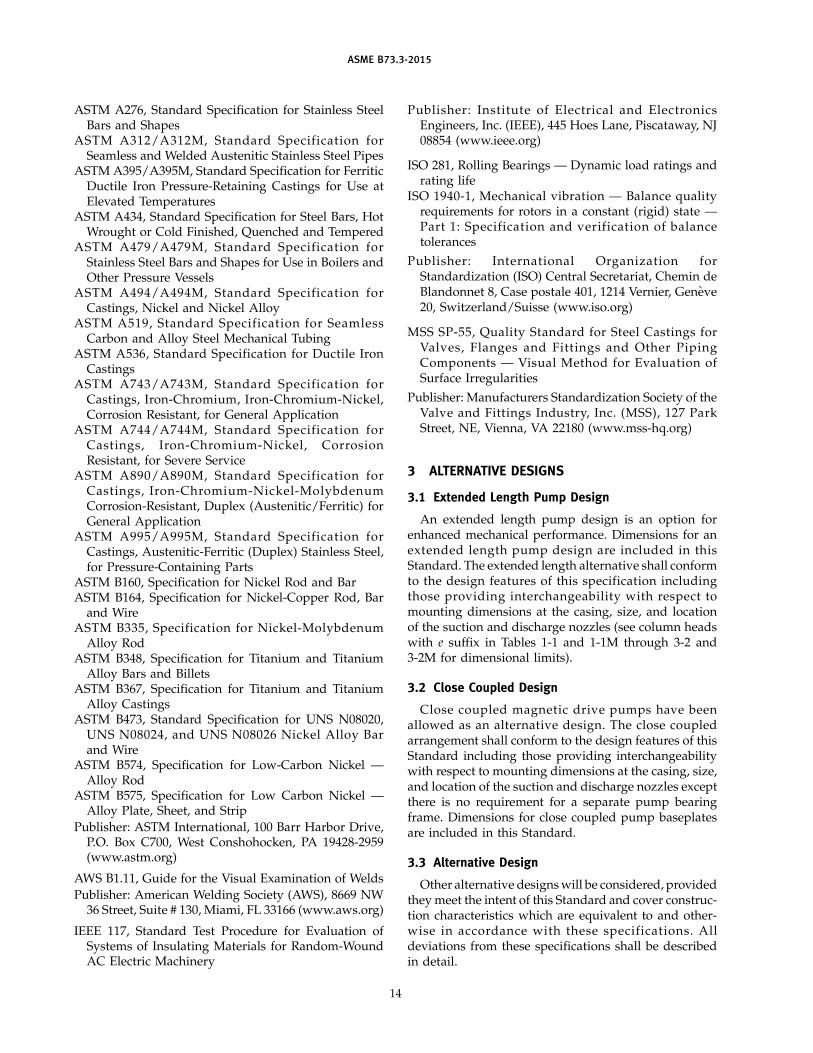
ASTM A276, Standard Specification for Stainless SteelBars and Shapes
ASTM A31 2/ A31 2M, Standard Specification forSeamless and Welded Austenitic Stainless Steel Pipes
ASTM A395/A395M, Standard Specification for FerriticDuctile Iron Pressure-Retaining Castings for Use atElevated Temperatures
ASTM A434, Standard Specification for Steel Bars, HotWrought or Cold Finished, Quenched and Tempered
ASTM A479/ A479M, Standard Specification forStainless Steel Bars and Shapes for Use in Boilers andOther Pressure Vessels
ASTM A494/ A494M, Standard Specification forCastings, Nickel and Nickel Alloy
ASTM A51 9 , Standard Specification for SeamlessCarbon and Alloy Steel Mechanical Tubing
ASTM A536, Standard Specification for Ductile IronCastings
ASTM A743/ A743M, Standard Specification forCastings, Iron-Chromium, Iron-Chromium-Nickel,Corrosion Resistant, for General Application
ASTM A744/ A744M, Standard Specification forCastings, Iron-Chromium-Nickel, CorrosionResistant, for Severe Service
ASTM A890/ A890M, Standard Specification forCastings, Iron-Chromium-Nickel-MolybdenumCorrosion-Resistant, Duplex (Austenitic/Ferritic) forGeneral Application
ASTM A995/ A995M, Standard Specification forCastings, Austenitic-Ferritic (Duplex) Stainless Steel,for Pressure-Containing Parts
ASTM B160, Specification for Nickel Rod and BarASTM B164, Specification for Nickel-Copper Rod, Bar
and WireASTM B335, Specification for Nickel-Molybdenum
Alloy RodASTM B348, Specification for Titanium and Titanium
Alloy Bars and BilletsASTM B367, Specification for Titanium and Titanium
Alloy CastingsASTM B473, Standard Specification for UNS N08020,
UNS N08024, and UNS N08026 Nickel Alloy Barand Wire
ASTM B574, Specification for Low-Carbon Nickel —Alloy Rod
ASTM B575, Specification for Low Carbon Nickel —Alloy Plate, Sheet, and Strip
Publisher: ASTM International, 100 Barr Harbor Drive,P.O. Box C700, West Conshohocken, PA 19428-2959(www.astm.org)
AWS B1.11, Guide for the Visual Examination of Welds
Publisher: American Welding Society (AWS), 8669 NW36 Street, Suite # 130, Miami, FL 33166 (www.aws.org)
IEEE 117, Standard Test Procedure for Evaluation ofSystems of Insulating Materials for Random-WoundAC Electric Machinery
14
Publisher: Institute of Electrical and ElectronicsEngineers, Inc. (IEEE), 445 Hoes Lane, Piscataway, NJ08854 (www.ieee.org)
ISO 281, Rolling Bearings — Dynamic load ratings andrating life
ISO 1940-1 , Mechanical vibration — Balance qualityrequirements for rotors in a constant (rigid) state —Part 1 : Specification and verification of balancetolerances
Publisher: International Organization forStandardization (ISO) Central Secretariat, Chemin deBlandonnet 8, Case postale 401, 1214 Vernier, Geneve20, Switzerland/Suisse (www.iso.org)
MSS SP-55, Quality Standard for Steel Castings forValves , Flanges and Fitt ings and Other Pip ingComponents — Visual Method for Evaluation ofSurface Irregularities
Publisher: Manufacturers Standardization Society of theValve and Fittings Industry, Inc. (MSS) , 127 ParkStreet, NE, Vienna, VA 22180 (www.mss-hq.org)
3 ALTERNATIVE DESIGNS
3.1 Extended Length Pump Design
An extended length pump design is an option forenhanced mechanical performance. Dimensions for anextended length pump design are included in thisStandard. The extended length alternative shall conformto the design features of this specification includingthose providing interchangeability with respect tomounting dimensions at the casing, size, and locationof the suction and discharge nozzles (see column headswith e suffix in Tables 1-1 and 1-1M through 3-2 and3-2M for dimensional limits).
3.2 Close Coupled Design
Close coupled magnetic drive pumps have beenallowed as an alternative design. The close coupledarrangement shall conform to the design features of thisStandard including those providing interchangeabilitywith respect to mounting dimensions at the casing, size,and location of the suction and discharge nozzles exceptthere is no requirement for a separate pump bearingframe. Dimensions for close coupled pump baseplatesare included in this Standard.
3.3 Alternative Design
Other alternative designs will be considered, providedthey meet the intent of this Standard and cover construc-tion characteristics which are equivalent to and other-wise in accordance with these specifications. Alldeviations from these specifications shall be describedin detail.
ASME B73.3-2015
4 NOMENCLATURE AND DEFINITIONS
4.1 Definitions of Terms
All nomenclature and definitions of pump compo-nents shall be in accordance with ANSI/HI 5.1 throughANSI/HI 5.6.
canned motor pump (CMP): a type of sealless pump wherethe impeller is mounted on the end of the shaft that isoverhung from its motor bearing supports. The impelleris mounted directly on the rotor assembly, making onerotor assembly. The bearings are supported by housingsat each end of the rotor assembly. The motor componentsare protected from the process liquid by corrosion resis-tant, nonmagnetic liners (shells). During operation, themotor section and bearings are either cooled and lubri-cated by the process liquid or a flush introduced froman external source.
close coupled magnetic drive pump: a sealless magneticdrive pump as defined below except the outer magnetring is mounted on the driver shaft.
magnetic drive pump (MDP): a type of sealless pumpwhere the impeller is mounted on a rotor assembly thatcontains the inner magnet ring of a magnetic drive.The process fluid is retained by a corrosion resistantcontainment shell that separates the inner magnet ringand the outer magnet ring. The outer magnet ring ismounted on the shaft of a frame that is coupled to amotor or power device.
plastic lined sealless pump: a type of sealless magneticdrive pump which consists of a metal outer casing cov-ered internally by a plastic lining for chemical resistance.The metal outer casing gives structural rigidity for pres-sure containment and externally applied nozzle loads.The containment shell may consist of a reinforced outershell with a plastic insert for chemical resistance, anengineered ceramic or other nonmetallic construction.All nonpressure-containing wetted parts are either cov-ered by a plastic lining or may be made of an engineeredceramic.
separately coupled magnetic drive pump: a sealless magneticdrive pump as defined above where the outer magnetring is mounted on the shaft of a frame that is separatelycoupled to a motor or power device and mounted on acommon baseplate.
4.2 Additional Definitions
auxiliary piping: includes all piping connected to thepump excluding the main piping connected at the pumpsuction and discharge flanges. Auxiliary piping includespiping, tubing, and all attached components such asvalves, instrumentation, and coolers.
nonpressure-containing nonwetted parts: pump parts thatdo not contain or retain pressure and are not wetted bythe pumped fluid.
15
nonpressure-containing wetted parts: pump parts that donot contain or retain pressure, but are wetted by thepumped fluid (e.g., wear ring).
pressure-containing nonwetted parts: pump parts that con-tain pressure but are not wetted by the pumped fluid(e.g., lined casing, cover).
pressure-containing wetted parts: pump parts that containpressure and are wetted by the pumped fluid (e.g. ,casing).
pressure-retaining nonwetted parts: pump parts that retainpressure but are not wetted by the pumped fluid (e.g.,adapter, fasteners).
supplier: manufacturer or manufacturer’s representativethat supplies the equipment.
5 DESIGN AND CONSTRUCTION FEATURES
5.1 Pressure and Temperature Limits
5.1 .1 Pressure Limits. Pressure limitations shall bestated by the pump manufacturer. See para. 5.11 forauxiliary piping.
5.1 .1 .1 The design pressure of the casing, casingcover, containment shell, and secondary containment, ifapplicable, shall be at least as great as the pressure–temperature rating of ASME B16.5 Class 150 flanges orASME B16.42 Class 150 flanges for the material used.
5.1 .1 .1 .1 For plastic lined sealless pumps, thepressure limitation for the material of construction of thecasing, casing cover, containment shell, and secondarycontainment, if applicable, shall have a design pressureat least equal to the pressure–temperature rating ofASME B16.42 Class 150 flanges. Pumps may be offeredwith higher design pressures than the minimum statedpressures. Pumps having lower design pressures thanthe minimum stated require approval by the purchaser.
5.1 .1 .2 The design pressure of jackets shall be atleast 100 psig (689 kPa gage) at 340°F (171°C). Heatingjackets may be required for jacket temperatures to 500°F(260°C) with a reduction in pressure corresponding tothe reduction in yield strength of the jacket material.
5.1 .1 .3 The casing, casing cover, and containmentshell (and secondary pressure-containing boundary andjackets, if applicable) shall be designed to withstand ahydrostatic test at 1.5 times the maximum design pres-sure for the particular component and material of con-struction used (see para. 6.3.1 .1).
5.1 .1 .4 All primary pressure-containing partsshall be capable of resist ing a vacuum of 1 4. 7 psi(760 mm HG) at 68°F (20°C).
5.1 .2 Temperature Limits. Temperature limitationsshall be as stated by the pump manufacturer includingtemperature limitations of the liquid at the suction
ASME B73.3-2015
flange. Pumps should be available for temperatures upto 500°F (260°C). Jacketing and other modifications maybe required to meet the operating temperature. Seepara. 5.11 for auxiliary piping.
The application of the pump shall take into consider-ation the fluid characteristics as supplied by the user.This will require consideration of such characteristicsas specific heat and vapor pressure of the liquid whichestablishes these limits.
5.1 .2.1 Plastic lined seallesss pumps should bedesignated for a minimum temperature range of −20°Fto 250°F (−29°C to 121°C).
5.2 Flanges
5.2.1 General. Suction and discharge nozzles shallbe flanged. Flange drilling, facing, and minimum thick-ness shall conform to ASME B1 6. 5 Class 1 50 orASME B16.42 Class 150 standards, except that markingrequirements are not applicable and the maximumacceptable tolerance on parallelism of the back of theflange shall be 3 deg. Flanges shall be flat-faced at thefull raised-face thickness (minimum) called for in theASME standards for the material of construction.Raised-face flanges may be offered as an option. Boltholes shall straddle the horizontal and vertical center-line. Bolt holes may be tapped when adequate space fornuts is not availab le behind flanges, as noted inTables 1-1, 1-1M, 3-1, 3-1M, 3-2, and 3-2M. Through boltholes are preferred. When tapped holes are supplied,they shall be noted on the outline drawing.
5 .2.1 .1 For plastic lined sealless pumps, therequirements under para. 5.2.1 apply except that raised-face flanges shall be standard. The raised-face portionof the flange is formed by the plastic lining.
5.2.2 Class 300 Option. As an option, Class 300flanges in accordance with ASME B16.5 or ASME B16.42may be offered with pressure ratings subject to the man-ufacturer ’s casing pressure–temperature limitations.Class 300 flanges shall be flat-faced at full raised-facethickness (minimum), or raised-face flanges may beoffered as an option.
5.2.2.1 Class 300 flanges are not a required optionfor plastic lined sealless pumps.
5.2.3 X and Y Dimensions. All pumps, regardlessof flange rating, shall conform to theX and Ydimensionsshown in Tables 1-1 and 3-1.
5.2.4 Heavy Hex Nuts. Where heavy hex nuts cannotbe used, the location shall be noted on the outlinedrawing.
NOTE: ASME B16.5 and ASME B16.42 indicate the use of heavyhex nuts for certain flange connections. On many B73 pumps,heavy hex nuts cannot be used due to available space. Standardhex nuts are often substituted. The use of standard hex nuts maynot allow the achievement of full bolt stress, which may impact
16
proper gasket compression. With most gasket materials, this doesnot reduce the gasket’s ability to properly seal. However, this is aconsideration for metallic and semi-metallic (i.e., spiral wound)gaskets where significant preload may be required to achieve suffi-cient tightness.
5.3 Casing
5.3.1 Drain Connection Boss(es). The pump casingshall have boss(es) to provide for drain connection(s) inthe lowest part of the casing. Boss size shall accommo-date 1⁄2 in. NPT minimum. Boss(es) shall be drilled andtapped when specified by the purchaser.
5.3.1 .1 For plastic lined sealless pumps, a drainshall be provided unless otherwise specified. The drainshall be at the lowest part of the pump casing. Whenprovided, the drain shall be sealed by a blind flangeand gasket. Screwed connections in plastic lined pumpsare prohibited.
5.3.2 Auxiliary Connection Boss(es). The suctionand discharge nozzles shall have boss(es) for gage con-nections. Boss size shall accommodate 1⁄4 in. NPT mini-mum, 1⁄2 in. NPT preferred. Boss(es) shall be drilled andtapped when specified by the purchaser.
5.3.2.1 For plastic lined sealless pumps, suctionand discharge gage connections are not required.
5.3.3 Support. The casing shall be supported byfeet beneath the casing or a suitable support betweenthe casing and baseplate. For CMP, an alternative pumpcradle between the stator and baseplate is acceptable.
5.3.4 Disassembly. The design shall permit backremoval of the rotating element(s) from the casing with-out disturbing the suction and discharge connections.The design shall also avoid disturbing the motor onseparately coupled MDP pumps. Tapped holes for jack-screws or equivalent means shall be provided to facilitatethe safe disassembly and reassembly of the rotating ele-ment(s) from the casing and to avoid the necessity ofdrive wedges or prying implements. Jackscrews shallnot cause damage to parts that will interfere withreassembly and sealing when the parts are reused.
5.3.5 Heating or Cooling
5.3.5.1 There are several methods of cooling orheating areas of most ASME B73.3 magnetic drive andcanned motor pumps. The pump casing, bearing hous-ing, and motor are areas that may have design featuresavailab le for heating or cooling. Commonly usedcooling/heating piping plans applied to ASME B73.3pump applications are identified in Fig. 5.3.5.1-1. Otherconfigurations may be used if specified and agreed uponbetween the supplier and purchaser.
5.3.5.2 Jackets for heating or cooling the casing,motor, and/or pump components are optional. Connec-tions shall be 3⁄8 in. NPT minimum, with 1⁄2 in. NPT
ASME B73.3-2015
Fig. 5.3.5.1 -1 Cooling and Heating Piping Plans
Cool ing or heating to
drive section
Plan A
Cool ing or heating to
casing jacket
Plan M
FI
Cool ing or heating to
heat exchanger
Plan P
FI
Cool ing or heating to
drive section and
casing jacket
Plan N
FI
External heat exchanger
Flow indicator
only when specified
Block valve
LEGEND
FI
FI
preferred. When a jacket is to be used with steam, theinlet connection shall be located at the top quadrant ofthe jacket, and the drain connection shall be located atthe bottom portion of the jacket to prevent the formationof water pockets. Jackets for liquid cooling or heatingshall have the outlet at the top and inlet at the bottomto prevent the formation of vapor pockets and a drainat the bottom for freeze protection.
5 .3 .5 .3 Heating or cooling j ackets are not arequired option for plastic lined sealless pumps.
5.3.6 Gaskets. All assembly gaskets shall be con-fined on the atmospheric side to prevent blowout.Design shall consider thermal cycling which may occuras a condition of service. Gaskets shall be selected sothe required seating stress is compatible with the avail-able bolt load (strength and area). The gasket materialshall be suitable for the service conditions and flangefacing/finish.
5.3.7 Bolting. The pressure-containing fasteners(including casing, containment shell, and secondary con-tainment or control components, if applicable) shall bedesigned to account for maximum allowable workingpressure (MAWP) and be capable of maintaining a sealon the gasket during operation. The fasteners shall have
17
a sufficient bolt area to assure that the resulting tensilestresses during design loading does not exceed theallowable bolt stresses given in ASME Section II, Part D(Table 3). In addition, the tapped holes for pressure-retaining bolting shall be of sufficient depth that threadengagement is 7⁄8 times the nominal bolt diameter. Whenthere are sufficient strength differences between thematerial of the tapped hole and the fastener, the designshall consider possible shearing of the threads of thetapped connection.
5.4 Impeller
5.4.1 Types. Impellers of open, semi-open, andclosed designs are optional.
5.4.2 Balance. Impellers shall meet ISO 1940-1 ,Grade G6.3 after final machining.
5.4.3 Attachment. For MDP rotating shaft designs,the impeller shall be keyed, threaded, or otherwise per-manently fixed to the shaft. Threads shall be designedto tighten by correct rotation. For CMP rotating shaftdesigns, the impeller shall be keyed or otherwise perma-nently fixed to the shaft. For stationary shaft designs,the impeller may be an integral part of the rotor assem-bly. Other attachment designs may be used with theapproval of the purchaser.
ASME B73.3-2015
5.5 Internal Drive Assembly
5.5.1 Mounting. For MDP rotating shaft designs,the inner magnet assembly shall be keyed, threaded, orpermanently attached to the impeller drive shaft.
5.5.2 Balance. The rotor assembly or inner mag-netic assembly shall be balanced in accordance withISO 1940-1, Grade G6.3.
5.5.3 Critical Speed. The first lateral critical speedof the rotating assembly shall be at least 120% of themaximum operating speed.
5.5.4 Fillets and Radii. All shaft shoulder fillets andradii shall be as large as practical and finished to reduceadditional stress risers.
5.5.5 Internal Drive Assembly Bearings
5.5.5.1 Bearing Design. The bearing system shallbe capable of absorbing all thrust and radial loads whilethe pump is operated within its allowable operatingrange. The thrust bearing should be designed to absorbthrust in either direction; however, no design shall beoffered where a change in thrust direction affects thepump hydraulic performance or reliability during nor-mal operation. In a design that relies on thrusting in onedirection during normal operation to maintain hydraulicperformance and reliability, reverse thrusting shall beallowed only during start-up, shutdown, or abnormaloperating conditions such as vapor entrainment, insuffi-c ient NPSHA, flow outside allowable operatingregion, etc.
Bearings shall be designed and applied consideringfluid characteristics, unit loading, speed, corrosion, ero-sion, wear, heat transfer, thermal cycling, fits, and mate-rial and friction characteristics.
5.5.5.2 Bearing Loading. Bearing loading, align-ment, shaft deflection, surface finish, and wear-incharacteristics of bearing materials shall be taken intoaccount to prevent local surface failure.
5.5.5.3 Journals. The journals may be separatesleeves, finished shaft surface, or hardfaced/coatedshaft areas for both rotating and non-rotating shaftdesigns.
5.5 .5 .4 Clearances. Materials used for journalsleeves, thrust collars, and bearings often have signifi-cantly different thermal expansion characteristics com-pared to shaft and other mating parts. Applicationguidelines and limits shall be established by the manu-facturers for specific designs to avoid breakage or loose-ness under specified operating temperatures ortemperature cycling.
5.5.5.5 Lubrication. Lubrication and/or cooling ofthe bearings shall be by the liquid pumped or by a clean,compatible, external fluid injection. Fluid circulationpiping plan designations shown in Fig. 5.3.2.12.1 of
18
ANSI/ HI 5 . 1 through 5. 6 shall be applied toASME B73.3 MDP and CMP applications. A modifiedPlan 114 may also be applied as shown in Fig. 5.5.5.5-1.Other configurations may be used if specified andagreed upon between the supplier and purchaser.
5.5.5.6 Heat Input. The bearings shall be providedwith adequate fluid circulation and pressure that consid-ers the maximum heat input of the drive assembly(including bearing friction) in relation to thefluid-specific gravity, the fluid-specific heat, fluid viscos-ity, laminar flow, turbulent flow, and vapor pressure.The pump design shall also ensure that the temperatureand pressure in the rotor chamber prevents vaporizationthrough the full operating range of the pump from mini-mum flow to maximum flow while providing continu-ous flow through the rotor chamber for cooling andbearing lubrication.
The pump design shall ensure the greater of thefollowing:
(a) The ratio between circulation return pressure andthe predicted vapor pressure at any point in the rotorchamber shall be a minimum of 1.1.
(b) The differential between circulation return pres-sure and the predicted vapor pressure at any point inthe rotor chamber shall be a minimum of 33 ft (10 m)of process fluid.
The user shall provide suction pressure, specific grav-ity, vapor pressure, specific heat, and viscosity data ver-sus temperature for use in these calculations.
5.5 .5 .7 Bearing Environment. The design shallprovide for removal of air or other noncondensables.The purchaser shall advise manufacturers of all changesin phase, solid content, or viscosity that may occur tothe process fluid due to a change in temperature and/orpressure.
5 .5 .5 .8 Filtration . When conditions of servicerequire filtration of bearing lubricating fluid, a self-cleaning internal design may be used. If external filtra-tion is required, the filter system should allow for indi-cating when filter change is required. Loss of flow todrive section shall be avoided.
5.6 Containment Design
5.6.1 Primary Pressure Containment. The contain-ment shell and liner shall be the primary means of seal-ing and as a minimum shall be manufactured of amaterial equal to or higher in corrosion/chemical resist-ance than the pump casing.
5.6.2 Magnetic Drive Pump. The magnetic drivepump metallic primary and/or secondary containmentshell(s) shall be designed in accordance with the tableof allowable stress levels for the selected materials andthe equations for the minimum required thickness asoutlined in Section VIII, Division 1, of the ASME Boiler
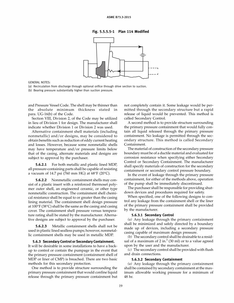
ASME B73.3-2015
Fig. 5.5.5.5-1 Plan 114 Modified
GENERAL NOTES:
(a) Recirculation from discharge through optional orifice through drive section to suction.
(b) Bearing pressure substantially higher than suction pressure.
and Pressure Vessel Code. The shell may be thinner thanthe absolute minimum thickness stated inpara. UG-16(b) of the Code.
Section VIII, Division 2, of the Code may be utilizedin lieu of Division 1 for design. The manufacturer shallindicate whether Division 1 or Division 2 was used.
Alternative containment shell materials (includingnonmetallic) and/or designs, may be considered toobtain benefits such as reduction of eddy current heatingand losses. However, because some nonmetallic shellsmay have temperature and/or pressure limits belowthat of the casing, alternate materials and designs aresubject to approval by the purchaser.
5.6.2.1 For both metallic and plastic lined MDP,all pressure-containing parts shall be capable of resistinga vacuum of 14.7 psi (760 mm HG) at 68°F (20°C).
5.6.2.2 Nonmetallic containment shells may con-sist of a plastic insert with a reinforced thermoset poly-mer outer shell, an engineered ceramic, or other typenonmetallic construction. The containment shell chemi-cal resistance shall be equal to or greater than the casinglining material. The containment shell design pressureat 100°F (38°C) shall be the same as the casing and casingcover. The containment shell pressure versus tempera-ture rating shall be stated by the manufacturer. Alterna-tive designs are subject to approval by the purchaser.
5.6.2.3 Metallic containment shells shall not beused in plastic lined sealless pumps; however, nonmetal-lic containment shells may be used in metallic MDP.
5.6.3 Secondary Control or Secondary Containment.It will be desirable in some installations to have a back-up to control or contain the pumpage in the event thatthe primary pressure containment (containment shell ofMDP or liner of CMP) is breached. There are two basicmethods for this secondary protection.
One method is to provide structure surrounding theprimary pressure containment that would confine liquidrelease through the primary pressure containment but
19
not completely contain it. Some leakage would be per-mitted through the secondary structure but a rapidrelease of liquid would be prevented. This method iscalled Secondary Control.
A second method is to provide structure surroundingthe primary pressure containment that would fully con-tain all liquid released through the primary pressurecontainment. No leakage is permitted through the sec-ondary structure. This method is called SecondaryContainment.
The material of construction of the secondary pressureboundary must be of a ductile material and evaluated forcorrosion resistance when specifying either SecondaryControl or Secondary Containment. The manufacturershall specify materials of construction for the secondarycontainment or secondary control pressure boundary.
In the event of leakage through the primary pressurecontainment, for either of the methods above, operationof the pump shall be immediately discontinued.
The purchaser shall be responsible for providing shut-down devices and procedures required for safety.
When specified, one of the following designs to con-trol any leakage from the containment shell or the linerof the primary pressure containment shall be providedby the manufacturer.
5.6.3.1 Secondary Control(a) Any leakage through the primary containment
shall be minimized and safely directed by a boundarymade up of devices, including a secondary pressurecasing capable of maximum design pressure.
(b) The secondary control shall be drainable to a resid-ual of a maximum of 2 in.3 (30 ml) or to a value agreedupon by the user and the manufacturer.
(c) The secondary control shall be provided with flushand drain connections.
5.6.3.2 Secondary Containment(a) Any leakage through the primary containment
shall be contained by secondary containment at the max-imum allowable working pressure for a minimum of48 hr.
ASME B73.3-2015
(b) The secondary containment shall be drainable toa residual of a maximum of 2 in.3 (30 ml) or to a valueagreed upon by the user and the manufacturer.
(c) The secondary containment shall be provided withflush and drain connections when specified.
5.6.3.2.1 Secondary Containment Verification.When specified, a means for periodically checking thesecondary containment, for sealing capability, shall beprovided by the manufacturer.
5.6.4 Draining. All pumped fluid-containing areas,including vendor-supplied piping, shall be drainable toa residual of a maximum of 2 in.3 (30 ml), or to a valueagreed upon by the manufacturer and purchaser, andshall be suitable for flushing before disassembly.
5.7 Bearings, Lubrication, and Bearing Frame (MDP)
5.7.1 External Bearings
5.7.1 .1 Bearing Design. Two rolling element bear-ing assemblies shall be provided: one assembly free tofloat within the bearing frame to carry radial loadingonly, and the other assembly fixed or located axially.
5.7.1 .2 Bearing Life. Bearings shall be selected inaccordance with ANSI/ABMA-9, ANSI/ABMA-11, andISO 281. The minimum L10 bearing life shall be 17,500 hrfor all standard and optional bearing frame arrange-ments of bearings, lubrication, shafts, covers, andsealing.
5.7.1 .2.1 For close coupled MDP, the suppliershall be responsible for assuring the motor bearing lifewhen calculated in accordance with ANSI/ABMA-9,ANSI/ABMA-11, and ISO 281 will provide a minimumL10 bearing life of 17,500 hr.
5.7.1 .3 Lubrication
5.7.1 .3.1 Oil bath lubrication is standard onseparately coupled MDP.
5.7.1 .3.1 .1 For close coupled MDP, greasedlubrication shall be standard. When regreaseable lubri-cation is specified, a means for grease relief shall beprovided.
5.7.1 .3.2 Oil mist lubrication shall be optional.When oil mist lubrication is specified, the location ofthe inlets, drains, and the vents should be mutuallyagreed upon between the purchaser and the supplier.
5.7.1 .3.3 Greased for life or regreaseable lubri-cation shall be optional on separately coupled MDP.When regreaseable lubrication is specified, a means forgrease relief shall be provided.
5.7.2 Bearing Frame. Bearing frame shall be con-structed to protect the bearings from water, dust, andother contaminants and provide lubrication for the bear-ings. The standard design is for oil bath lubrication and
20
is to include labyrinth-type bearing isolators, a 1 in.(25 mm) bull’s-eye oil sight glass, magnetic drain plug,and plugged top vent.
5.7.2.1 Sealing. The standard design is to includelabyrinth-type bearing isolators. In addition, optionaldesigns may be offered that allow for the use of a varietyof other bearing frame seals, such as lip seals or magneticoil seals, as may be specified by the purchaser. In thosecases where the bearing frame seal does not allow thebearing frame pressure to equalize with atmosphericpressure during operation, an expansion chamber orbreather is necessary.
5.7.2.2 Bearing Frame Drain. Bearing frame shallbe provided with a tapped and plugged drain hole atits lowest point. A magnetic drain plug shall be used.
5.7.2.3 Lubricant Level Indication. Bearing framefor oil bath lubrication shall be provided with a 1 in.(25 mm) bull’s-eye level indicator that is capable ofoptionally being installed on either side or both sidesof the bearing frame. The proper oil level for thenon-operating pump shall be indicated on the outsideof the bearing frame.
5.7.2.4 Constant Level Oiler. A constant level oileris not part of the standard design but may be includedas an option when specified. If a constant level oiler issupplied, it shall be set initially by the supplier for theproper level during operation.
5.8 Outer Magnet Assembly (MDP)
5.8.1 Mounting. The outer magnet assembly shallbe positively driven and runout shall be limited to pre-vent contact with stationary components during normaloperation. Connections shall not loosen during reverserotation.
5.8.2 Containment Shell Protection. The pump shallbe designed to delay the outer magnet ring from con-tacting the containment shell in the event of a shaft orbearing failure. When specified, the design shall utilizea device of non-sparking material to minimize anysource of ignition.
5.8.3 Corrosion Resistance. The surfaces of ferrousmaterials of the outer carrier, frame, and magnets shallhave a heat resistant paint or coating to protect thesesurfaces from corrosion.
5.8.4 Balance. The outer magnet assembly shall bebalanced to a minimum ISO 1940-1, Grade G6.3.
5.8.5 Critical Speed. The first lateral critical speedof the rotating assembly shall be at least 120% of themaximum operating speed.
5.8.6 Fillets and Radii. All shaft shoulder fillets andradii shall be as large as practical and finished to reduceadditional stress risers.
ASME B73.3-2015
5.9 Stator Assembly (CMP)
5.9.1 Stator Windings. The stator windings shallbe protected by a corrosion-resistant liner suitable forthe specified conditions.
5.9.2 Filled Stators. For filled stators, the secondarycontainment components of the stator assembly shallmeet the requirements of para. 5.6.3.2. Supplier shallprovide the user with the Material Safety Data Sheet(MSDS) of the filling medium in the stator assembly.The user must confirm that the stator filling medium iscompatible with the process fluid in the event of a pri-mary containment failure.
5.9.3 Temperature Rating. Motor stator windingsshall be designed to operate at or below the temperaturevalues established for the grade of insulation in accor-dance with IEEE 117. Maximum fluid temperature,motor winding temperature rise due to motor ineffi-ciency, heat input of the process fluid, filling of the statorcavity with a heat conductive medium, pump fluid circu-lation plan, and auxiliary cooling plan shall all be consid-ered in determining the maximum motor windingtemperature for the application.
5.9.4 Motor Design Life. Motor sizing, stator insula-tion rating, cooling fluid temperature and flow, thermalisolation, and use of jackets or heat exchangers shall bedesigned and selected to provide a minimum of175,000 hr design life at specified operating conditions.
5.9.5 Thermal Protection. Thermal protection shallbe provided. The manufacturer shall advise the tempera-ture setting and supply the applicable wiring diagrams.When specified, lower temperature setting thermal pro-tection shall be provided.
5.9.6 Hazardous Locations. Motors, electrical com-ponents, and electrical installations shall be suitable forthe area electrical classification (Class, Group, Division,and T Code), as well as national and local codes asspecified by the purchaser.
5.10 Materials of Construction
5.10.1 General
5.10.1 .1 The identifying material of a pump shallbe that of which the casing is constructed.
5.10.1 .2 The pump material classification codein Table 5.10.1 .2-1 shall be used to specify the pumpmaterials of construction for metallic MDP and CMP.
5.10.1 .2.1 For plastic lined MDP, the pumpmaterial classification code in Table 5. 10.1 .2-1 withBase Code MDP-X shall be used to specify the pumpmetallic, nonmetallic, and plastic materials of construc-tion for the casing, impeller, cover, pump shaft, contain-ment shell, and secondary containment/ control (if
21
furnished). Listed below are common polymer materialsused in plastic lined MDP:
(a) polytetrafluoroethylene (PTFE): nearly universalchemical resistance with a temperature limit of 350°F(177°C)
(b) perfluoroalkoxy (PFA): nearly universal chemicalresistance with a temperature limit of 350°F (177°C)
(c) ethylene tetrafluoroethylene (ETFE): very goodchemical resistance with a temperature limit of 250°F(121°C)
(d) polyvinylidine fluoride (PVDF) : good chemicalresistance with a temperature limit of 250°F (121°C)
5.10.1 .3 The pump part materials shall be inaccordance with the specific ASTM material specifica-tions in Table 5.10.1 .3-1 for each of the listed materialdesignations.
5.10.1 .4 Other materials shall be agreed uponby the purchaser and the supplier.
5 .1 0.1 .5 No repair by plugging, peening, orimpregnation is allowed on any parts wetted by thepumped fluid.
5.11 Auxiliary Piping
5.11 .1 Auxiliary piping shall, as a minimum, beavailable with the materials of construction in accor-dance with Table 5.11.1-1.
5 .1 1 .2 Auxiliary piping in contact with thepumped fluid shall have a pressure/temperature ratingequal to, or greater than the maximum allowable work-ing pressure (MAWP) of the pump. Auxiliary pipingwhich may become exposed to pumped fluid in theevent of a failure shall meet this requirement.
5.11 .3 Auxiliary piping and components normallyin contact with the pumped fluid shall have a corrosionresistance to the pumped fluid that is equal to, or betterthan that of the casing.
5.12 Corrosion Allowance
All wetted components of the pump shall be made ofmaterials that are corrosion resistant to the fluids beingpumped at the maximum rated process temperature.For corrosive fluids, the wetted components shall beagreed upon between the purchaser and supplier byconsideration of corrosion rates for fluids, process tem-peratures, and materials.
5.13 Direction of Rotation
Direction of rotation shall be clockwise when viewedfrom the motor end of the pump. An arrow showingthe direction of rotation shall be provided, either cast onthe casing or stamped on a plate of durable constructionaffixed to the pump in a prominent location.
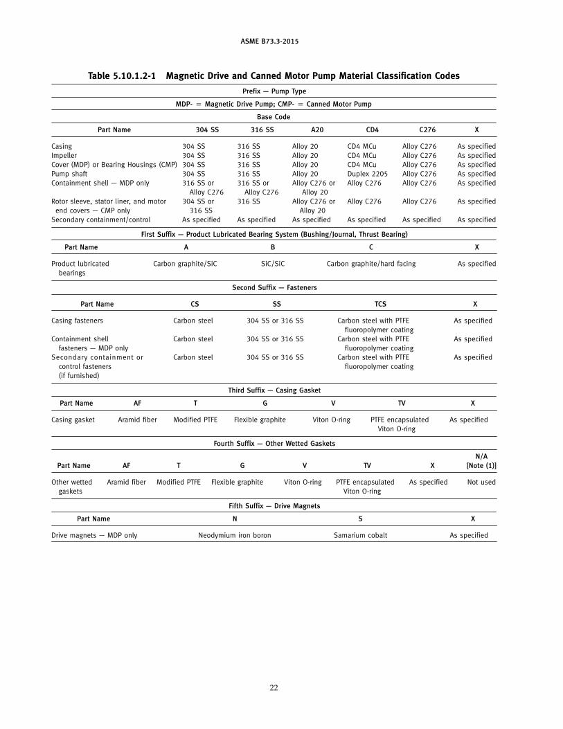
ASME B73.3-2015
Table 5.10.1 .2-1 Magnetic Drive and Canned Motor Pump Material Classification Codes
Prefix — Pump Type
MDP- p Magnetic Drive Pump; CMP- p Canned Motor Pump
Base Code
Part Name 304 SS 316 SS A20 CD4 C276 X
Casing 304 SS 316 SS Alloy 20 CD4 MCu Alloy C276 As specified
Impeller 304 SS 316 SS Alloy 20 CD4 MCu Alloy C276 As specified
Cover (MDP) or Bearing Housings (CMP) 304 SS 316 SS Alloy 20 CD4 MCu Alloy C276 As specified
Pump shaft 304 SS 316 SS Alloy 20 Duplex 2205 Alloy C276 As specified
Containment shell — MDP only 316 SS or 316 SS or Alloy C276 or Alloy C276 Alloy C276 As specified
Alloy C276 Alloy C276 Alloy 20
Rotor sleeve, stator liner, and motor 304 SS or 316 SS Alloy C276 or Alloy C276 Alloy C276 As specified
end covers — CMP only 316 SS Alloy 20
Secondary containment/control As specified As specified As specified As specified As specified As specified
First Suffix — Product Lubricated Bearing System (Bushing/Journal, Thrust Bearing)
Part Name A B C X
Product lubricated Carbon graphite/SiC SiC/SiC Carbon graphite/hard facing As specified
bearings
Second Suffix — Fasteners
Part Name CS SS TCS X
Casing fasteners Carbon steel 304 SS or 316 SS Carbon steel with PTFE As specified
fluoropolymer coating
Containment shell Carbon steel 304 SS or 316 SS Carbon steel with PTFE As specified
fasteners — MDP only fluoropolymer coating
Second ary con ta i nmen t or Carbon steel 304 SS or 316 SS Carbon steel with PTFE As specified
control fasteners fluoropolymer coating
(if furn ished)
Third Suffix — Casing Gasket
Part Name AF T G V TV X
Casing gasket Aramid fiber Modified PTFE Flexible graphite Viton O-ring PTFE encapsulated As specified
Viton O-ring
Fourth Suffix — Other Wetted Gaskets
N/A
Part Name AF T G V TV X [Note (1 )]
Other wetted Aramid fiber Modified PTFE Flexible graphite Viton O-ring PTFE encapsulated As specified Not used
gaskets Viton O-ring
Fifth Suffix — Drive Magnets
Part Name N S X
Drive magnets — MDP only Neodymium iron boron Samarium cobalt As specified
22
ASME B73.3-2015
Table 5.10.1 .2-1 Magnetic Drive and Canned Motor Pump Material Classification Codes (Cont’d)
GENERAL NOTES:
(a) As an example, the pump material classification code MDP 316SS-B-SS-AF-V-S indicates the following for a magnetic drive pump:
(1 ) casing p 316 SS
(2) impeller p 316 SS
(3) cover p 316 SS
(4) pump shaft p 316 SS
(5) containment shell p Alloy C276
(6) secondary containment/control p as specified
(7) product lubricated bearing system p SiC/SiC
(8) casing fasteners p 304 SS or 316 SS
(9) containment shell fasteners p 304 SS or 316 SS
(10) secondary containment or control fasteners (if furnished) p 304 SS or 316 SS
(11 ) casing gasket p aramid fiber
(12) other wetted gaskets p Viton
(13) drive magnets p samarium cobalt
(b) As an example, the pump material classification code CMP 316SS-C-SS-AF-V indicates the following for a canned motor pump:
(1 ) casing p 316 SS
(2) impeller p 316 SS
(3) bearing housings p 316 SS
(4) pump shaft p 316 SS
(5) rotor sleeve, stator liner, motor end covers p 316 SS
(6) secondary containment/control p as specified
(7) product lubricated bearing system p carbon graphite/hard facing
(8) casing fasteners p 304 SS or 316 SS
(9) secondary containment or control fasteners (if furnished) p 304 SS or 316 SS
(10) casing gasket p aramid fiber
(1 1 ) other wetted gaskets p Viton
NOTE:
(1 ) For MDP, if casing and containment shell gasket are the same, select N/A.
23
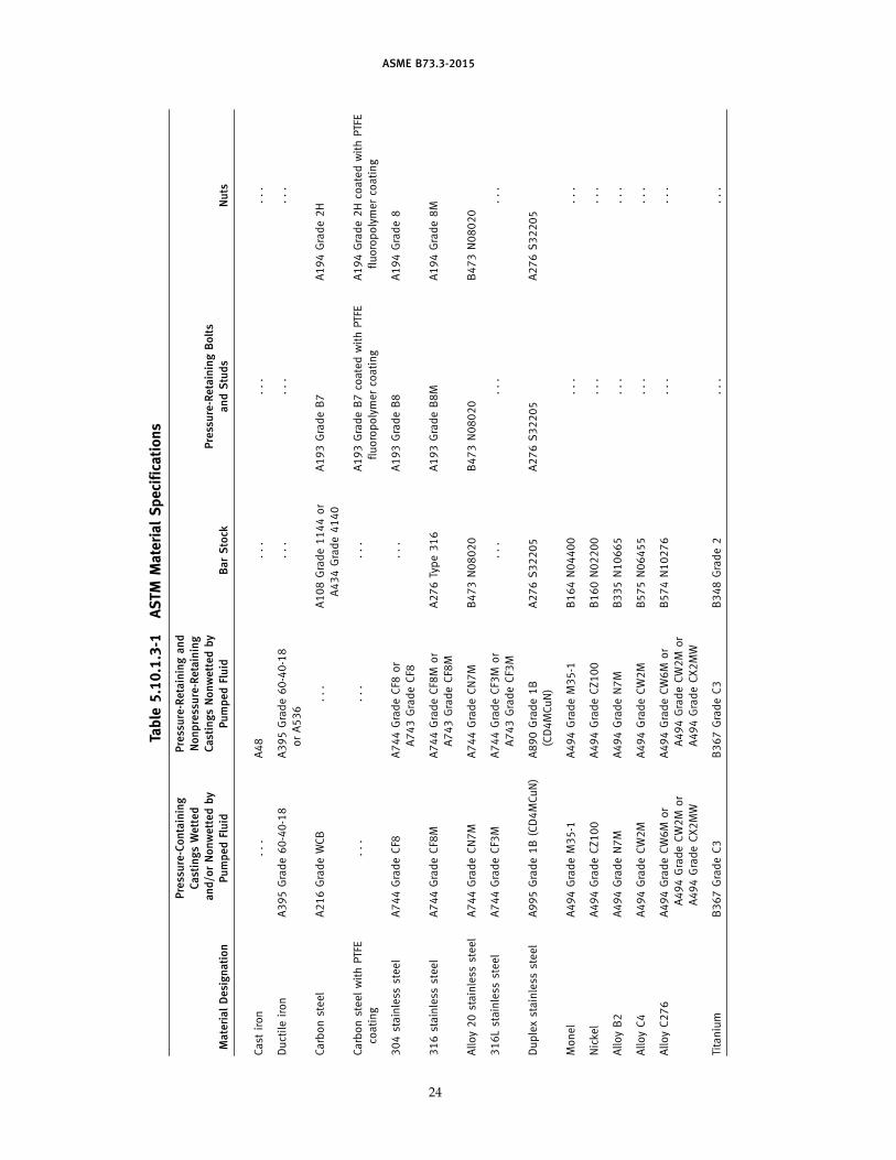
ASME B73.3-2015
Table
5.10.1.3-1
ASTM
MaterialSpecifica
tions
Pressure-Containing
Pressure-Retainingand
CastingsWetted
Nonpressure-Retaining
and/orNonwettedby
CastingsNonwettedby
Pressure-RetainingBolts
MaterialDesignation
PumpedFluid
PumpedFluid
BarStock
andStuds
Nuts
Cast
iron
...
A48
...
...
...
Ductileiron
A395Grade60-40-18
A395Grade60-40-18
...
...
...
orA536
Carbonsteel
A216GradeWCB
...
A108Grade1144or
A193GradeB7
A194Grade2H
A434Grade4140
CarbonsteelwithPTFE
...
...
...
A193GradeB7coatedwithPTFE
A194Grade2HcoatedwithPTFE
coating
fluoropolymercoating
fluoropolymercoating
304stainless
steel
A744GradeCF8
A744GradeCF8
or
...
A193GradeB8
A194Grade8
A743GradeCF8
316stainless
steel
A744GradeCF8M
A744GradeCF8M
or
A276Type316
A193GradeB8M
A194Grade8M
A743GradeCF8M
Alloy20stainless
steel
A744GradeCN7M
A744GradeCN7M
B473N08020
B473N08020
B473N08020
316Lstainless
steel
A744GradeCF3M
A744GradeCF3M
or
...
...
...
A743GradeCF3M
Duplexstainless
steel
A995Grade1B(CD4MCuN)
A890Grade1B
A276S32205
A276S32205
A276S32205
(CD4MCuN)
Monel
A494GradeM35-1
A494GradeM35-1
B164N04400
...
...
Nickel
A494GradeCZ100
A494GradeCZ100
B160N02200
...
...
AlloyB2
A494GradeN7M
A494GradeN7M
B335N10665
...
...
AlloyC4
A494GradeCW2M
A494GradeCW2M
B575N06455
...
...
AlloyC276
A494GradeCW6M
or
A494GradeCW6M
or
B574N10276
...
...
A494GradeCW2M
or
A494GradeCW2M
or
A494GradeCX2MW
A494GradeCX2MW
Titanium
B367GradeC3
B367GradeC3
B348Grade2
...
...
24
ASME B73.3-2015
Table 5.11 .1 -1 Minimum Requirements for Auxiliary Piping Materials
ASTM Material Requirements by Type
Tubing Pipe Fittings
Tube Fittings PipeMaterial Size Range: 3⁄8-in. O.D. to
3⁄4-in. O.D. ASME B16.11
Designation Minimum Wall Thickness: 0.035 in. Compression Type Schedule 40 Min. Class 2000 Min.
Carbon steel A519 (seamless) A108 A106 Grade B A105
(seamless)
316 stainless steel Seamless A269 Grade TP316 Bar Stock: A479, Type 316 Seamless A312 A182 Grade F316
Forgings: A182, Grade F316 Grade TP316
5.14 Dimensions
Pump dimensions shall conform to Table 1-1 and 1-1Mor 3-1 and 3-1M. Baseplate dimensions shall conform toTables 1-2, 1-2M, 2-1, 2-1M, or 3-2 and 3-2M.
5.15 Miscellaneous Design Features
5.15.1 Safety Guards. Each coupling shall be fur-nished with a coupling guard. The coupling guard shallprevent personnel from contacting rotating components.Regional regulations and purchaser requirements mayrequire additional guards. All guards shall meet theperformance criteria of ANSI B11.19.
5.15.1 .1 Safety guards are not applicable to closecoupled MDP or CMP.
5.15.2 Threads. All threaded parts, such as bolts,nuts, and plugs, shall conform to ASME standardsunless otherwise specified.
5.15.3 Lifting Rings (MDP). A lifting ring or otherequivalent device shall be provided to facilitate handlingthe frame and associated assembly if its mass exceeds60 lb (27 kg). For magnetic drive pumps on bedplates,eyebolts on motors and/or pumps are not suitablefor lifting the entire pump and motor assembly. Thepump manufacturer ’s manual shall provide liftinginstructions.
5 .1 5 .4 Tapped Open ings. All tapped openingswhich may be exposed to the pumped fluid under pres-sure (including the secondary containment where fur-nished) shall be plugged with threaded metal plugs.Plugs normally in contact with the pumped fluid shallbe of the same material as the case, except that carbonsteel plugs may be used on ductile iron pumps. Threadedplugs shall not be used in the heating or cooling jacketpiping connections; instead, snap-in plugs or waterprooftape shall be used to relieve possible pressure accumula-tion until piping is installed.
5.15.5 Venting. The entire unit including casing,drive section, and piping supplied by the manufacturershall be self-venting or furnished with vent connections.
5.15.6 Identification. The manufacturer’s part iden-tification number and material designation shall be cast,
25
clearly die stamped, or etched on the casing, cover,impeller, and containment shell. The manufacturers shallprovide identification on the product lubricated bear-ings (tagging is acceptable) to assist in parts identifica-tion prior to assembly.
5.15.7 Installation. All equipment provided shallbe designed for unsheltered outdoor installation andoperation at specified ambient temperatures.
5.15.8 Frame (MDP). The frame shall be designedto resist a torque at least as high as the decoupling torquestrength of the largest drive magnets available for thatframe.
The frame, when it clamps the rear cover plate to thepump casing, would be classified as a pressure-retainingpart and shall be made of a suitable ductile materialsuch as cast ductile iron or cast carbon steel. When thebearing frame is specified for secondary control or sec-ondary containment it shall be constructed of a ductilematerial.
5.15.9 Baseplates. Baseplates shall be designed inaccordance with ANSI/HI 1.3, which includes grouted,ungrouted, pregrouted, and freestanding baseplates.
5.15.9.1 Baseplate Options. If specified, the fol-lowing baseplate options shall be available:
(a) fabricated steel construction with continuouswelding (no skip welds)
(b) pump and motor mounting surfaces machined flatand parallel within 0.002 in./ft (0.17 mm/m)
(c) full drain rim with surface sloped to minimum1 in. NPT drain connection to allow complete drainage
(d) motor alignment adjusters
(e) devices to allow lifting of complete unit (pump,motor, baseplate, and attached auxiliaries)
5.15.9.2 Baseplate Rigidity (MDP). Baseplates, forseparately coupled pumps, which are to be freestanding(foot or spring supported rather than held by anchorbolts and grouted) shall be so structurally rigid as tolimit movement of the driver shaft relative to the pumpdrive shaft to 0.002 in. (0.05 mm) parallel offset whenthe driver torque of nameplate horsepower is applied.
ASME B73.3-2015
5 .1 5 .9 .2 .1 Freestanding foot-mountedbaseplates shall meet the load and deflection criteria ofANSI/HI 9.6.2, para. 9.6.2.1 .7.1 .1 .
5 .1 5 .9 .2 .2 Freestanding spring-mountedbaseplates shall meet the stress and rigidity require-ments of ANSI/HI 1.3, para. 1.3.8.4; allowable nozzleloads shall be mutually agreed upon between the sup-plier and purchaser.
5.16 Monitoring Devices
5.16.1 Description. Devices or instruments thatindicate or control the condition of the sealless pumpto preclude misoperation or damage to the unit shouldbe available when specified.
5.16.2 Temperature Probe. Sensing of temperatureof the recirculation fluid and/or the containment shellshould be available when specified. Location of temper-ature sensors shall be agreed upon between the pur-chaser and manufacturer.
5.16.2.1 Sensing of temperature of the recircula-tion fluid and/or the containment shell for plastic linedMDP is not a required option.
5.16.3 Bearing Wear Detector (CMP). A device todetect axial and radial wear for a minimum of one bear-ing should be available when specified.
5.16.4 Vibration. When vibration transducers arespecified they must be mounted in such a way as tonot adversely affect the accuracy of the measurements.Acceptable mounting methods for permanent rigidmount or temporary mount transducers shall be inaccordance with ANSI/HI 9.6.4. MDP bearing housingmeasurement locations and directions for separatelycoupled type OH1 (ASME B73.1) pumps and close cou-pled type OH7 pumps shall be in accordance withANSI/HI 9.6.4, Fig. 9.6.4.2. 3. 1 . For CMP type OH9pumps, the location shall be on the motor end cover inthe horizontal, vertical, and axial positions as shown inFig. 5.16.4-1.
5.16.5 Motor. A device that monitors the motorshould be available when specified. This device maydetect one or more of the following:
(a) power
(b) phase imbalance
(c) under current
(d) over current
(e) single phasing
(f) short circuit or internal malfunction
5.16.6 Circulation Fluid. A device to monitor theflow rate of the circulation fluid should be availablewhen specified. This requirement will only apply topumps with external circulation and does not apply tointernal circulated pumps.
26
5 .1 6.7 Direction of Rotation Indicator (CMP). Adirection of rotation indicator should be available whenspecified.
5.16.8 Leak Detection. A device to detect leakagefrom the primary containment liner for CMP or contain-ment shell for MDP shall be available when specified.
6 GENERAL INFORMATION
6.1 Application
Application of sealless pumps requires more consider-ation than that for conventional centrifugal pumps. It isrecommended that anyone applying this type of equip-ment read para . 5 . 3 , Design and Application, ofANSI/HI 5.1 through 5.6.
6.1 .1 Terminology. Terminology shall be in accor-dance with ANSI/HI 5.1 through 5.6 and ANSI/HI 14.6except as NPSHR is clarified in para. 6.1 .7.
6.1 .2 Nozzle Loading. Allowable nozzle loadingimposed by the piping shall be in accordance withANSI/HI 9.6.2.
6.1 .3 Sound. The maximum sound pressure levelproduced by the pump and driver shall comply withthe limit specified by the purchaser. Tests, if specified,shall be conducted in accordance with the standards ofANSI/HI 9.1/9.5. Driver noise data must be determinedseparately.
6.1 .4 Vibration. The vibration level measured onthe pump bearing frame, when specified, at the suppli-er ’s test facility at the rated condition point (speed ±5%,flow ±5%) shall not exceed allowable “factory” pumpbearing housing vibration limits shown inANSI/HI 9.6.4, Fig. 9.6.4.2.5.1a, for type OH7 and OH11MDP or type OH9 CMP unless otherwise agreed uponbetween the supplier and purchaser.
6.1 .5 Hydraulic Coverage. Tables 6.1 .5-1 and 6.1.5-2show the approximate hydraulic coverage for 50 Hz and60 Hz.
6.1 .6 Operating Region
6.1 .6.1 Allowable Operating Region. Pumps shallbe designed to operate continuously between 110% ofthe flow at the Best Efficiency Point and the minimumflows shown in Table 6.1.6.1-1, unless specifically notedotherwise by the manufacturer, and meet the require-ments of paras. 5.5.5 (internal drive assembly bearings),5.7.1 .2 (external bearing life), and 6.1.4 (vibration) whenpumping water at ambient conditions.
CAUTION: The values in Table 6.1.6.1-1 do not consider mini-
mum thermal flow for a specific installation; therefore, the practi-
cal minimum operating flow may be higher than shown. Pumped
fluid is heated as it goes through the drive section of a sealless
pump and the minimum thermal flow is that where the tempera-
ture rises enough through the pump that recirculation of some
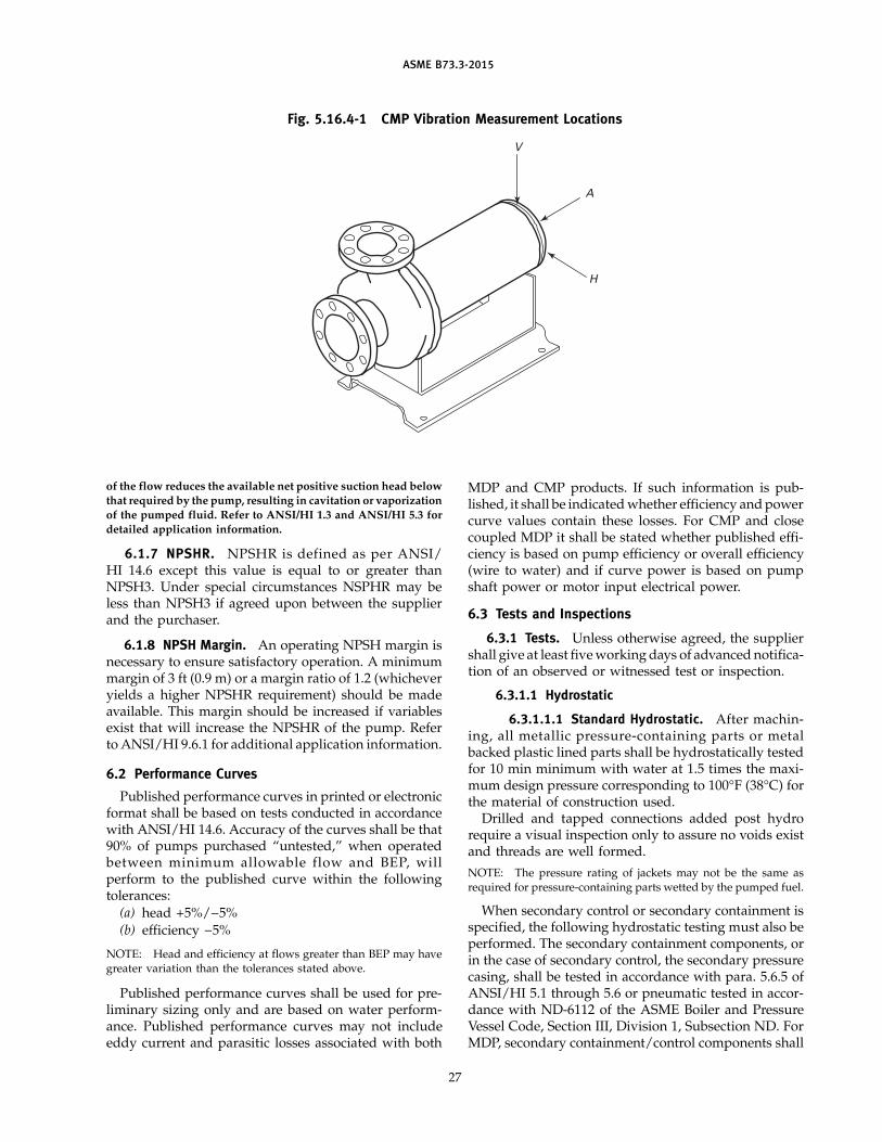
ASME B73.3-2015
Fig. 5.16.4-1 CMP Vibration Measurement Locations
V
A
H
of the flow reduces the available net positive suction head below
that required by the pump, resulting in cavitation or vaporization
of the pumped fluid. Refer to ANSI/HI 1.3 and ANSI/HI 5.3 for
detailed application information.
6.1 .7 NPSHR. NPSHR is defined as per ANSI/HI 14.6 except this value is equal to or greater thanNPSH3. Under special circumstances NSPHR may beless than NPSH3 if agreed upon between the supplierand the purchaser.
6.1 .8 NPSH Margin. An operating NPSH margin isnecessary to ensure satisfactory operation. A minimummargin of 3 ft (0.9 m) or a margin ratio of 1.2 (whicheveryields a higher NPSHR requirement) should be madeavailable. This margin should be increased if variablesexist that will increase the NPSHR of the pump. Referto ANSI/HI 9.6.1 for additional application information.
6.2 Performance Curves
Published performance curves in printed or electronicformat shall be based on tests conducted in accordancewith ANSI/HI 14.6. Accuracy of the curves shall be that90% of pumps purchased “untested,” when operatedbetween minimum allowable flow and BEP, willperform to the published curve within the followingtolerances:
(a) head +5%/−5%
(b) efficiency −5%
NOTE: Head and efficiency at flows greater than BEP may havegreater variation than the tolerances stated above.
Published performance curves shall be used for pre-liminary sizing only and are based on water perform-ance. Published performance curves may not includeeddy current and parasitic losses associated with both
27
MDP and CMP products. If such information is pub-lished, it shall be indicated whether efficiency and powercurve values contain these losses. For CMP and closecoupled MDP it shall be stated whether published effi-ciency is based on pump efficiency or overall efficiency(wire to water) and if curve power is based on pumpshaft power or motor input electrical power.
6.3 Tests and Inspections
6.3.1 Tests. Unless otherwise agreed, the suppliershall give at least five working days of advanced notifica-tion of an observed or witnessed test or inspection.
6.3.1 .1 Hydrostatic
6.3.1 .1 .1 Standard Hydrostatic. After machin-ing, all metallic pressure-containing parts or metalbacked plastic lined parts shall be hydrostatically testedfor 10 min minimum with water at 1.5 times the maxi-mum design pressure corresponding to 100°F (38°C) forthe material of construction used.
Drilled and tapped connections added post hydrorequire a visual inspection only to assure no voids existand threads are well formed.
NOTE: The pressure rating of jackets may not be the same asrequired for pressure-containing parts wetted by the pumped fuel.
When secondary control or secondary containment isspecified, the following hydrostatic testing must also beperformed. The secondary containment components, orin the case of secondary control, the secondary pressurecasing, shall be tested in accordance with para. 5.6.5 ofANSI/HI 5.1 through 5.6 or pneumatic tested in accor-dance with ND-6112 of the ASME Boiler and PressureVessel Code, Section III, Division 1, Subsection ND. ForMDP, secondary containment/control components shall
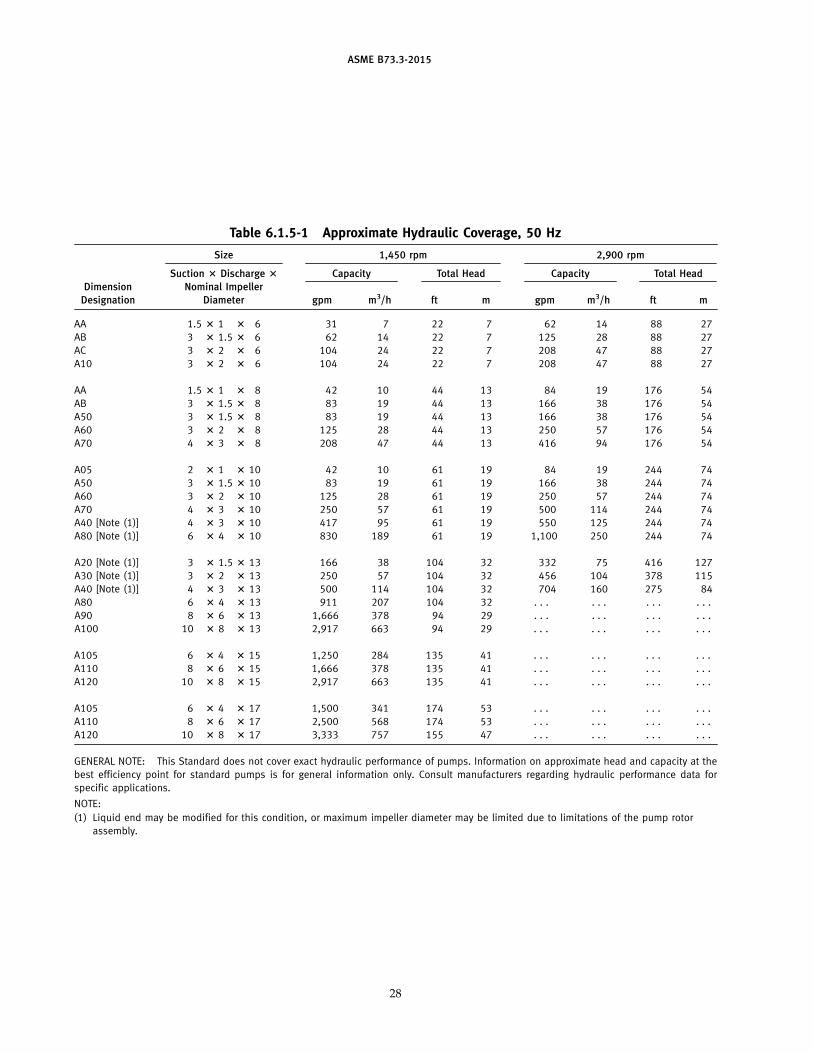
ASME B73.3-2015
Table 6.1 .5-1 Approximate Hydraulic Coverage, 50 Hz
Size 1 ,450 rpm 2,900 rpm
Suction ? Discharge ? Capacity Total Head Capacity Total Head
Dimension Nominal Impeller
Designation Diameter gpm m3/h ft m gpm m3/h ft m
AA 1 .5 ? 1 ? 6 31 7 22 7 62 14 88 27
AB 3 ? 1 .5 ? 6 62 14 22 7 125 28 88 27
AC 3 ? 2 ? 6 104 24 22 7 208 47 88 27
A10 3 ? 2 ? 6 104 24 22 7 208 47 88 27
AA 1 .5 ? 1 ? 8 42 10 44 13 84 19 176 54
AB 3 ? 1 .5 ? 8 83 19 44 13 166 38 176 54
A50 3 ? 1 .5 ? 8 83 19 44 13 166 38 176 54
A60 3 ? 2 ? 8 125 28 44 13 250 57 176 54
A70 4 ? 3 ? 8 208 47 44 13 416 94 176 54
A05 2 ? 1 ? 10 42 10 61 19 84 19 244 74
A50 3 ? 1 .5 ? 10 83 19 61 19 166 38 244 74
A60 3 ? 2 ? 10 125 28 61 19 250 57 244 74
A70 4 ? 3 ? 10 250 57 61 19 500 114 244 74
A40 [Note (1 ) ] 4 ? 3 ? 10 417 95 61 19 550 125 244 74
A80 [Note (1 ) ] 6 ? 4 ? 10 830 189 61 19 1 ,100 250 244 74
A20 [Note (1 ) ] 3 ? 1 .5 ? 13 166 38 104 32 332 75 416 127
A30 [Note (1 ) ] 3 ? 2 ? 13 250 57 104 32 456 104 378 115
A40 [Note (1 ) ] 4 ? 3 ? 13 500 114 104 32 704 160 275 84
A80 6 ? 4 ? 13 911 207 104 32 . . . . . . . . . . . .
A90 8 ? 6 ? 13 1 ,666 378 94 29 . . . . . . . . . . . .
A100 10 ? 8 ? 13 2,917 663 94 29 . . . . . . . . . . . .
A105 6 ? 4 ? 15 1 ,250 284 135 41 . . . . . . . . . . . .
A110 8 ? 6 ? 15 1 ,666 378 135 41 . . . . . . . . . . . .
A120 10 ? 8 ? 15 2,917 663 135 41 . . . . . . . . . . . .
A105 6 ? 4 ? 17 1 ,500 341 174 53 . . . . . . . . . . . .
A110 8 ? 6 ? 17 2,500 568 174 53 . . . . . . . . . . . .
A120 10 ? 8 ? 17 3,333 757 155 47 . . . . . . . . . . . .
GENERAL NOTE: This Standard does not cover exact hydraulic performance of pumps. Information on approximate head and capacity at the
best efficiency point for standard pumps is for general information only. Consult manufacturers regarding hydraulic performance data for
specific applications.
NOTE:
(1 ) Liquid end may be modified for th is condition, or maximum impeller diameter may be limited due to limitations of the pump rotor
assembly.
28
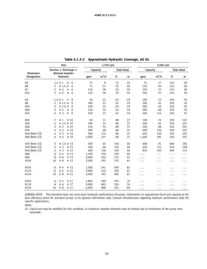
ASME B73.3-2015
Table 6.1 .5-2 Approximate Hydraulic Coverage, 60 Hz
Size 1 ,750 rpm 3,500 rpm
Suction ? Discharge ? Capacity Total Head Capacity Total Head
Dimension Nominal Impeller
Designation Diameter gpm m3/h ft m gpm m3/h ft m
AA 1 .5 ? 1 ? 6 37 8 32 10 75 17 125 38
AB 3 ? 1 .5 ? 6 75 17 32 10 150 34 125 38
AC 3 ? 2 ? 6 125 28 32 10 250 57 125 38
A10 3 ? 2 ? 6 125 28 32 10 250 57 125 38
AA 1 .5 ? 1 ? 8 50 11 63 19 100 23 250 76
AB 3 ? 1 .5 ? 8 100 23 63 19 200 45 250 76
A50 3 ? 1 .5 ? 8 100 23 63 19 200 45 250 76
A60 3 ? 2 ? 8 150 34 63 19 300 68 250 76
A70 4 ? 3 ? 8 250 57 63 19 500 114 250 76
A05 2 ? 1 ? 10 50 11 88 27 100 23 350 107
A50 3 ? 1 .5 ? 10 100 23 88 27 200 45 350 107
A60 3 ? 2 ? 10 150 34 88 27 300 68 350 107
A70 4 ? 3 ? 10 300 68 88 27 600 136 350 107
A40 [Note (1 ) ] 4 ? 3 ? 10 500 114 88 27 650 148 350 107
A80 [Note (1 ) ] 6 ? 4 ? 10 1 ,000 227 88 27 1 ,300 295 350 107
A20 [Note (1 ) ] 3 ? 1 .5 ? 13 200 45 150 46 400 91 600 183
A30 [Note (1 ) ] 3 ? 2 ? 13 300 68 150 46 550 125 550 168
A40 [Note (1 ) ] 4 ? 3 ? 13 600 136 150 46 850 193 400 122
A80 6 ? 4 ? 13 1 ,100 250 150 46 . . . . . . . . . . . .
A90 8 ? 6 ? 13 2,000 454 135 41 . . . . . . . . . . . .
A100 10 ? 8 ? 13 3,500 795 135 41 . . . . . . . . . . . .
A105 6 ? 4 ? 15 1 ,500 341 200 61 . . . . . . . . . . . .
A110 8 ? 6 ? 15 2,000 454 200 61 . . . . . . . . . . . .
A120 10 ? 8 ? 15 3,500 795 200 61 . . . . . . . . . . . .
A105 6 ? 4 ? 17 1 ,800 409 250 76 . . . . . . . . . . . .
A110 8 ? 6 ? 17 3,000 682 250 76 . . . . . . . . . . . .
A120 10 ? 8 ? 17 4,000 909 225 69 . . . . . . . . . . . .
GENERAL NOTE: This Standard does not cover exact hydraulic performance of pumps. Information on approximate head and capacity at the
best efficiency point for standard pumps is for general information only. Consult manufacturers regarding hydraulic performance data for
specific applications.
NOTE:
(1 ) Liquid end may be modified for th is condition, or maximum impeller diameter may be limited due to limitations of the pump rotor
assembly.
29
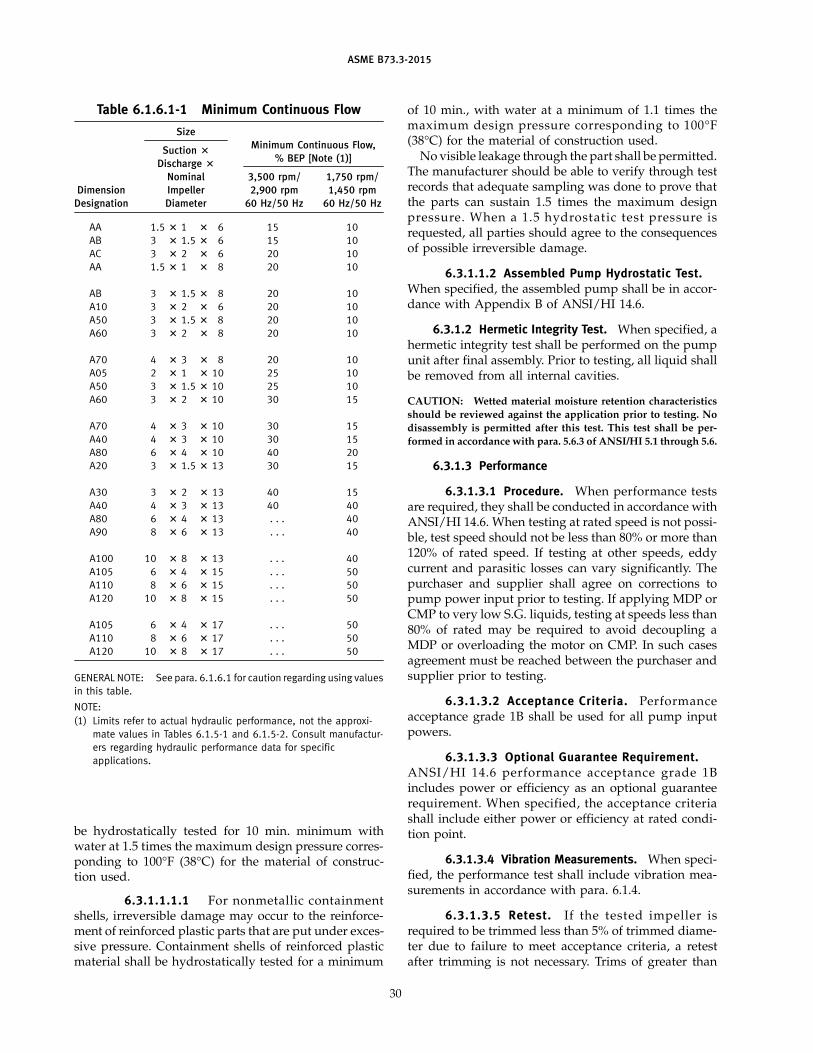
ASME B73.3-2015
Table 6.1 .6.1 -1 Minimum Continuous Flow
Size
Minimum Continuous Flow,Suction ?
% BEP [Note (1 )]Discharge ?
Nominal 3,500 rpm/ 1 ,750 rpm/
Dimension Impeller 2,900 rpm 1 ,450 rpm
Designation Diameter 60 Hz/50 Hz 60 Hz/50 Hz
AA 1 .5 ? 1 ? 6 15 10
AB 3 ? 1 .5 ? 6 15 10
AC 3 ? 2 ? 6 20 10
AA 1 .5 ? 1 ? 8 20 10
AB 3 ? 1 .5 ? 8 20 10
A10 3 ? 2 ? 6 20 10
A50 3 ? 1 .5 ? 8 20 10
A60 3 ? 2 ? 8 20 10
A70 4 ? 3 ? 8 20 10
A05 2 ? 1 ? 10 25 10
A50 3 ? 1 .5 ? 10 25 10
A60 3 ? 2 ? 10 30 15
A70 4 ? 3 ? 10 30 15
A40 4 ? 3 ? 10 30 15
A80 6 ? 4 ? 10 40 20
A20 3 ? 1 .5 ? 13 30 15
A30 3 ? 2 ? 13 40 15
A40 4 ? 3 ? 13 40 40
A80 6 ? 4 ? 13 . . . 40
A90 8 ? 6 ? 13 . . . 40
A100 10 ? 8 ? 13 . . . 40
A105 6 ? 4 ? 15 . . . 50
A110 8 ? 6 ? 15 . . . 50
A120 10 ? 8 ? 15 . . . 50
A105 6 ? 4 ? 17 . . . 50
A110 8 ? 6 ? 17 . . . 50
A120 10 ? 8 ? 17 . . . 50
GENERAL NOTE: See para. 6.1 .6.1 for caution regarding using values
in th is table.
NOTE:
(1 ) Limits refer to actual hydraulic performance, not the approxi-
mate values in Tables 6.1 .5-1 and 6.1 .5-2. Consult manufactur-
ers regarding hydraulic performance data for specific
applications.
be hydrostatically tested for 10 min. minimum withwater at 1.5 times the maximum design pressure corres-ponding to 100°F (38°C) for the material of construc-tion used.
6.3.1 .1 .1 .1 For nonmetallic containmentshells, irreversible damage may occur to the reinforce-ment of reinforced plastic parts that are put under exces-sive pressure. Containment shells of reinforced plasticmaterial shall be hydrostatically tested for a minimum
30
of 10 min., with water at a minimum of 1.1 times themaximum design pressure corresponding to 1 00°F(38°C) for the material of construction used.
No visible leakage through the part shall be permitted.The manufacturer should be able to verify through testrecords that adequate sampling was done to prove thatthe parts can sustain 1.5 times the maximum designpressure . When a 1 . 5 hydrostat ic test pressure isrequested, all parties should agree to the consequencesof possible irreversible damage.
6.3.1 .1 .2 Assembled Pump Hydrostatic Test.When specified, the assembled pump shall be in accor-dance with Appendix B of ANSI/HI 14.6.
6.3.1 .2 Hermetic Integrity Test. When specified, ahermetic integrity test shall be performed on the pumpunit after final assembly. Prior to testing, all liquid shallbe removed from all internal cavities.
CAUTION: Wetted material moisture retention characteristics
should be reviewed against the application prior to testing. No
disassembly is permitted after this test. This test shall be per-
formed in accordance with para. 5.6.3 of ANSI/HI 5.1 through 5.6.
6.3.1 .3 Performance
6.3.1 .3.1 Procedure. When performance testsare required, they shall be conducted in accordance withANSI/HI 14.6. When testing at rated speed is not possi-ble, test speed should not be less than 80% or more than120% of rated speed. If testing at other speeds, eddycurrent and parasitic losses can vary significantly. Thepurchaser and supplier shall agree on corrections topump power input prior to testing. If applying MDP orCMP to very low S.G. liquids, testing at speeds less than80% of rated may be required to avoid decoupling aMDP or overloading the motor on CMP. In such casesagreement must be reached between the purchaser andsupplier prior to testing.
6.3 .1 .3 .2 Acceptance Cri teria. Performanceacceptance grade 1B shall be used for all pump inputpowers.
6.3.1 .3.3 Optional Guarantee Requirement.ANSI/ HI 1 4. 6 performance acceptance grade 1 Bincludes power or efficiency as an optional guaranteerequirement. When specified, the acceptance criteriashall include either power or efficiency at rated condi-tion point.
6.3.1 .3.4 Vibration Measurements. When speci-fied, the performance test shall include vibration mea-surements in accordance with para. 6.1 .4.
6.3 .1 .3 .5 Retest. If the tested impeller isrequired to be trimmed less than 5% of trimmed diame-ter due to failure to meet acceptance criteria, a retestafter trimming is not necessary. Trims of greater than
ASME B73.3-2015
5% require a retest. If a new impeller is required, a retestis required.
6.3.1 .3.6 Written Record. A complete writtenrecord of the relevant test information including per-formance curves, the date of the tests, and the signatureof the person(s) responsible for conducting the tests shallbe delivered as part of the pump documentation.
6.3 .1 .3 .7 Addi tional Data. Additional data,when specified, may be taken during the performancetest. These data may include such things as vibration,bearing housing temperature, oil sump temperature, etc.Unless otherwise specified, the additional data will betaken at the rated duty point. When these data are speci-fied, they shall be conducted in accordance withANSI/HI 14.6.
6.3.1 .4 Net Positive Suction Head Required (NPSHR)Test. When specified, NPSHR tests shall be conductedin accordance with ANSI/HI 14.6. Unless otherwiseagreed to by the purchaser and supplier, the NPSH testwill be a Type II test, which is for determination ofNPSH3 at the rated flow only.
6.3.1 .5 Winding Integrity Test for Canned MotorPumps. The motor test shall be conducted in accordancewith para. 5.6.4 of ANSI/HI 5.1 through 5.6.
6.3.2 Inspections
6.3.2.1 Final Inspection. A final inspection maybe specified by the purchaser. If specified, the purchaseror purchaser’s representative will be given access to thecompleted pump assembly for visual inspection of theassembly prior to shipment.
6.3.2.2 Dismantle and Inspect After Test. If speci-fied, the pump shall be dismantled and inspected aftertest. Inspection procedure and criteria must be agreedupon by the purchaser and supplier.
6.3.2.3 Inspection of Connection Welds. When avisual inspection of weld connection is specified, it shallbe conducted in accordance with AWS B1.11 for evalua-tion of size of weld, undercut, and splatter. A completewritten record of welder, date of welding, method, andfiller material must be retained.
6.3.2.4 Inspection of Castings. When inspectionof cast parts wetted by the process fluid is specified, avisual inspection shall be conducted in accordance withMSS SP-55 for evaluation of cast surfaces. Inspection ofthe castings by other nondestructive methods such asdye penetrant or x-ray may be agreed upon between themanufacturer and purchaser.
6.4 Nameplates
The nameplate(s) is to be of 24 US Standard Gauge(minimum) AISI 300 series stainless steel and shall be
31
securely attached to the pump. The nameplate data isto be based on rated application conditions.
6.4.1 MDP. The MDP nameplate shall be stamped orembossed to include pump model, standard dimensiondesignation, serial number, pump size, magnetic cou-pling torque rating for 100°F (38°C), impeller diameterinstalled, maximum allowable impeller diameter (for theinstalled magnetic coupling), material of construction,maximum design pressure for 100°F (38°C), and ratedspeed.
6.4.2 CMP. The CMP nameplate shall be stamped orembossed to include pump model, standard dimensiondesignation, serial number, impeller diameter installed,maximum impeller diameter based on installed motorsize, material of construction, maximum design pressurefor 100°F (38°C), volts, full load amps, speed, insulationclass, shaft brake horsepower, full load kW, locked rotorcode, hertz, phase, phase sequence, and operating tem-perature code.
7 DOCUMENTATION
7.1 General
The documentation specified covers the minimumrequired to provide clear communication between thepump user and pump manufacturer and to facilitate thesafe design, installation, and operation of the pump.Additional data, as required for specific purposes, shallbe available, if requested. It is the intent that informationbe furnished in a similar form from all sources toimprove clarity and foster efficient utilization of thedocumentation.
7.2 Requirements
The following documents shall be supplied for eachpump item furnished:
(a) pump and driver outline drawing(b) centrifugal pump data sheet
(c) manufacturers cooling/heating piping drawing (ifapplicable)
(d) pump fluid circulation plan(e) performance curve with rating point(f) cross-sectional drawing with parts list
(g) instruction manual(h) motor wiring diagram (CMP)(i) coupling outline drawing, parts list, and alignment
tolerance limits(j) documentation for specified performance test
7.3 Document Description
7.3.1 Pump and Driver Outline Drawing(a) The pump and driver outline drawing may con-
tain all information shown on, and may be arranged as,the sample outline drawing included herein and identi-fied as Figs. 7.3.1-1 and 7.3.1-2.
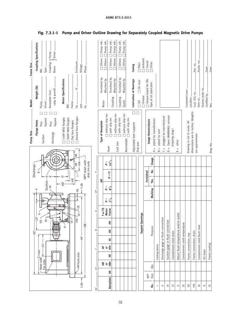
ASME B73.3-2015
Fig. 7.3.1 -1 Pump and Driver Outline Drawing for Separately Coupled Magnetic Drive PumpsPumpSize
Model
FrameSize
FlangeHoles
Weight(lb)
CouplingSpecifications
Suction
Thru
Pump
Mfr.
Tapped
Driver
Type
Baseplate
(incl.
Coupling
Pump
Discharge
Thru
cplg.&guard)
Bores
Driver
}Tapped
MotorSpecifications
Mfr.
150#ANSIflanges
Frame
300#ANSIflanges
hp
sfEnclosure
Flatface
flanges
rpm
Voltage
Raisedface
flanges
Hz
Phase
VIXI
X
VII
V
VIII
1.25
NPT drain w
ith
drip rim
only
Discharge
Suction
I
1.25
Near side
Far side
HH hole size
HF
HB
IV
II
III
IXHL
HD
DX
HG
HE
HE
HA
YCP
HC
C m
ax
CC
HC
CC
CD
XCP
Y
HD
TypeofBaseplate
Motor
Furnishedby
Others
Pumpmfr.
T or TS
Motor
Frame
Mountedby
Others
Pumpmfr.
DD
DSteel
withoutdrip rim
Baseplate
HA
HB
or
HBe
HE
HF
or
HFe
HL
HG
HH
51 /4
81 /4
141 /2
withdrip rim
Coupling
Furnishedby
Others
Pumpmfr.
Mountedby
Others
Pumpmfr.
Cast
iron
withoutdrip rim
withdrip rim
Nonmetallic
withoutdrip rim
withdrip rim
Coupling
Furnishedby
Others
Pumpmfr.
Guard
Mountedby
Others
Pumpmfr.
Adjustable
footsupports
Drippan
LubricationofBearings
Casing
Oil
Oilmist
Plain
TappedOpenings
UsageNomenclature
Grease
Jacketed
Furnished
A=
pipedbymanufacturer
Grease-lubedforlife
Traced
NPT
Typeofoillubricator:
Other
B=
pipedbyuser
No.
Size
Qty.
Purpose
Marking
Yes
No
Usage
C=
pluggedbymanufacturer
ICasing drains
D=
Open(W
ARNING:remove
IIDischargegage
orflush
connection
shippingplug.)
III
Suctiongage
orflush
connection
E=
other
IVContainmentshelldrain
VReturn
flush
temperature
and/oroutlet
VI
Containmentshelltemperature
Customer/user
Drawingis
notto
scale.All
VII
Frameconnection:top
Location
dim
ensionsare
ininches.
Weights
VIII
Frameconnection:drain
Cust.P.O.no.
Ser.no.
are
approximate.
Item
no.
Equip.no.
IXContainmentshellflush
inlet
Factory
orderno.
XOildrain
Certifiedby
Date
XI
Framecooling
Dwg.No.
Rev.
Date
D =10
32
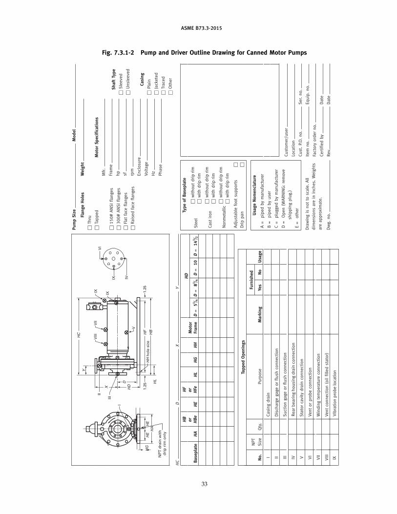
ASME B73.3-2015
Fig. 7.3.1 -2 Pump and Driver Outline Drawing for Canned Motor Pumps
PumpSize
Model
FlangeHoles
Weight
Thru
Tapped
MotorSpecifications
Mfr.
Frame
ShaftType
150#ANSIflanges
hp
Sleeved
300#ANSIflanges
sfUnsleeved
Flatface
flanges
rpm
Raisedface
flanges
Enclosure
Casing
Voltage
Plain
Hz
Jacketed
Phase
Traced
VIII
II
III
1.25
I
IX
IX
V
HH hole size
VII
HF
1.25
HC
Y
X HD
HE
HG
HE
HA
D
HB
Other
HC
DX
Y
HD
Motor
Baseplate
HA
HB
or
HBe
HF
or
HFe
HE
HL
HG
HH
Frame
D=51 /4D=81 /4
D=10
D=141 /2
TappedOpenings
Furnished
NPT
No.
Size
Qty.
Purpose
Marking
Yes
No
Usage
ICasingdrain
IIDischargegageorflush
connection
III
Suctiongageorflush
connection
Customer/user
IVRear bearing housing drain connection
Vibration probe location
Location
Cust.P.O.no.
Ser.no.
VStatorcavity
drain
connection
Drawingis
notto
scale.All
Item
no.
Equip.no.
VI
Ventorprobeconnection
dim
ensionsare
ininches.
Weights
Factory
orderno.
VII
Windingtemperature
connection
are
approximate.
Certifiedby
Date
VIII
IX
Ventconnection(oilfilledstator)
Dwg.no.
Rev.
Date
TypeofBaseplate
Steel
withoutdrip rim
withdrip rim
Cast
iron
withoutdrip rim
withdrip rim
Nonmetallic
withoutdrip rim
withdrip rim
Adjustable
footsupports
Drippan UsageNomenclature
A=
pipedbymanufacturer
B=
pipedbyuser
C=
pluggedbymanufacturer
D=
Open(W
ARNING:remove
shippingplug.)
E=
other
HL
IX IV
VI
NPT drain w
ith
drip rim
only
33
ASME B73.3-2015
(b) Tapped openings, when supplied, shall be identi-fied with the following markings:
Marking Purpose
I Casing drain
II Discharge gage or flush connectionIII Suction gage or flush connection
IV Containment shell drain (MDP) ; rear bearinghousing drain connection (CMP)
V Return flush temperature and/or outlet (MDP);stator cavity drain connection (CMP)
VI Containment shell temperature (MDP); vent orprobe connection (CMP)
VII Frame connection: top (MDP); winding tempera-ture connection (CMP)
VIII Frame connection: drain (MDP); vent connection —oil filled stator (CMP)
IX Containment shell flush inlet (MDP); vibrationprobe (CMP)
X Oil drain
XI Frame cooling
7.3.2 Sealless Centrifugal Pump Data Sheet(a) Data Sheet. The ASME Sealless Centrifugal Pump
Data Sheet in Mandatory Appendix I shall be used forall pumps covered by this Standard when the data sheetis initiated by the purchaser. The data sheet, electronicor printed copy, shall be used for inquiry, proposal, andas-built.
(b) Electronic Data. See Nonmandatory Appendix A.
7.3.3 Fluid Circulation Piping Drawing(a) The fluid circulation piping drawing shall be
included if the pump is fitted with a circulation pipingsystem supplied by the pump manufacturer.
(b) The fluid circulation piping drawing shall containinformation and uniform nomenclature consistent withthe sample schematics and references given inpara. 5.5.5.5.
7.3.4 Cooling/Heating Piping Drawing(a ) A cooling/ heating pip ing drawing shall be
included if the pump assembly is fitted with aheating/cooling piping system supplied by the pumpmanufacturer.
(b) The cooling/heating piping drawing shall containinformation and uniform nomenclature consistent withthe sample schematics and references given inFig. 5.3.5.1-1.
7.3.5 Performance Curve
7.3.5 .1 Single-Speed Performance. The single-speed performance curve shall be the composite (family)type curve for full impeller diameter range, plottinghead against flow and including efficiency, minimumflow, NPSHR, power consumption, and speed. Powerconsumption shall be provided at all flows includingshutoff. The composite (family) curve may not be practi-cal for specific pump design configurations and the pub-lication of such curves is at the discretion of the
34
manufacturer. If such information is published, it is tobe indicated whether the efficiency and power curvevalues contain the eddy current losses and parasiticlosses associated with both MDP and CMP products.Performance curves may be categorized as published,proposal, as-built, and test.
7.3.5.1 .1 The published, or catalog, perform-ance curve shall be as stated above and is based onambient temperature water. These performance curvesare normally found in the manufacturer ’s catalogs orelectronic media and do not reflect a pump configuredfor a specific pumping application.
7.3.5.1 .2 The proposal performance curve shallbe as stated above. The design impeller diameter shallbe indicated with the rated duty point identified onthe curve. It is not necessary to include the completecomposite (family) curves; however, the maximum andminimum impeller diameter head-flow curves must beincluded. An ISO power line shall be included reflectingthe MDP magnetic coupling rating or CMP motor ratingbased on the application. When the pumped fluid vis-cosity or specific gravity affects the pump performance,the proposal performance curve shall be corrected forthese effects. Magnetic coupling losses for MDP andmotor losses for CMP shall be reflected in the proposalperformance curve. The proposal performance curvesare normally supplied as part of a pump proposal andreflect a pump that has been configured for the specificpumping application.
7.3.5.1 .3 As-built, or as-configured, perform-ance curves shall be as stated for the proposal perform-ance curves and they must be for the pumpconfiguration actually supplied to the purchaser. As-built, or as-configured, performance curves are providedas part of the pump final documentation package.
7.3.5.2 Variable Speed Performance. When vari-able speed operation is specified, variable speed per-formance curves shall be provided. The requirementsand categories of variable speed curves are the same asfor single-speed curves (para. 7.3.5.1), except that thecurve will show a composite of curves with a singleimpeller trim when operated over a range of speeds.The speed for each curve will be clearly indicated.
7.3.5.3 Performance Test Curve. The performancetest curve, if specified, shall be at rated speed and asdescribed in para. 6.3.1 .3.6 and provided as part of thepump final documentation package.
7.3.6 Cross-Sectional Drawing. The cross-sectionaldrawing shall show all components of the pump. It shallbe complete with a parts list referenced to the drawing.Nomenclature and definitions should be in accordancewith ANSI/HI 5.1 through 5.6.
ASME B73.3-2015
7.3.7 Instruction Manual(a) The instruction manual should include informa-
tion on the correct installation, preparation for start-up,starting up, operation, trouble checklist, and mainte-nance information for the model pump assemblyfurnished.
(b) Any limitation or warning on the installation,operation, etc., of the unit should be clearly defined.
(c) The instruction manual shall be in electronic orprinted format.
(d) The use of a single manual to describe many simi-lar models of pumps should be minimized to reduceuser confusion on the exact model furnished.
(e) Recommended tolerance for coupling alignmentshall be supplied to the purchaser.
(f) Instruction manual for the pump driver, coupling,etc., shall be furnished if included in the scope of supply.For CMP, if a bearing monitoring system is provided,details as to operation and setup shall be included inthe manual.
(g) A guideline for developing instruction manualsmay be found in ANSI/HI 1.4.
7.3.8 Coupling Data. For separately coupled MDP,the motor to bearing frame flexible coupling data shallinclude: manufacturer, type, model, size, spacer length,materials of construction, and hub-to-shaft attachmentmethod.
7.3.9 Driver. For MDP, the pump driver data shallinclude manufacturer, nameplate, and dimensional data.
7.4 Specially Requested Documentation
Documentation in addition to that listed in para. 7.3shall be made available when specified.
7.4.1 Master Document List(a) This is a composite list of all documents submitted
by the manufacturer, including title of document anddrawing or other identification numbers, including revi-sion dates.
(b) This list shall be submitted along with the firstdocument in order for the user to be aware of the docu-ments that will follow.
35
(c) Revisions to this document list shall be made asrequired.
7.4.2 Allowable External Forces and Moments onNozzles List. This list summarizes the allowable exter-nal forces and moments on the pump suction and dis-charge nozzles (see para. 6.1 .2).
7.4.3 Parts List
(a) A list of all pump parts with pump identificationnumbers, part numbers, and material descriptions shallbe supplied. This list shall be as-built.
(b) A list of recommended spare parts shall be sup-plied and shall be subdivided into two categories:
(1 ) for start-up
(2) for 3 yr of operation
(c) A spare parts list for auxiliary equipment shall besupplied with the pump. This would include, as applica-ble, coupling, driver, gear boxes, etc.
(d) These lists shall be presented to the purchaserbefore the equipment is shipped, and reflect the as-builtequipment.
7.4.4 Special Operating and Design Data. Specialoperating and design data required by the user shall besupplied. This may include the following:
(a) minimum pump flow rate
(b) maximum allowable casing pressure andtemperature
(c) maximum allowable jacket pressure, flow rate, andtemperature
(d) external flush flow rate and pressure for seallesspump drive section
7.4.5 Special Testing, Painting, and Preparation.Any special testing, painting, and preparation requiredshall be specified on the sealless centrifugal pump datasheet.
7.4.6 Statement ofCompliance. A statement of com-pliance shall be included if specified. This statement ofcompliance shall include assurance that the pump isbeing supplied according to the requirements of thisStandard.
INTENTIONALLY LEFT BLANK
36
ASME B73.3-2015
MANDATORY APPENDIX IASME SEALLESS CENTRIFUGAL PUMP DATA SHEET
See Forms I-1 and I-1M on the following pages.
37
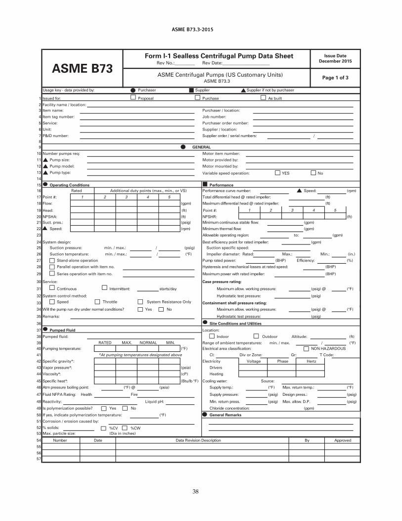
ASME B73.3-2015
resahcrup yb ton fi reilppuSreilppuSresahcruP:yb dedivorp atad - yek egasU
esahcruPlasoporP:rof deussI1 As bui lt
2 Faci l i ty name / location:
3 Item name: Purchaser / location:
4 Item tag number: Job number:
5 Service: Purchaser order number:
6 Unit: Supplier / location:
7 P&ID number: /:srebmun laires / redro reilppuS
8
9
1 0 Motor i tem number:
1 1 Pump size: Motor provided by:
1 2 Pump model: Motor mounted by:
1 3 Pump type: Variable speed operation:
1 4
1 5 ecnamrofrePsnoitidnoC gnitarepO
1 6 )mpr(:deepS:rebmun evruc ecnamrofreP
1 7 Point #: )tf(:rellepmi detar @ daeh laitnereffid latoT
1 8 Flow: )tf(:rellepmi detar @ daeh laitnereffid mumixaM)mpg(
1 9 Head: (ft) Point #:
:RHSPN)tf(:AHSPN02 (ft)
)mpg(:wolf elbats suounitnoc muminiM)gisp( Suct. pres. :12
)mpg(:wolf lamreht muminiM)mpr(:deepS22
23 )mpg(:noiger gnitarepo elbawollA
24 System design: )mpg(:rellepmi detar rof tniop ycneiciffe tseB
25 Suction pressure: min. / max. : / (psig) Suction specific speed:
26 Suction temperature: min. / max. : / (°F) Impeller diameter: Rated: Max.: Min. : ( in . )
)%(:ycneiciffE)PHB(:rewop detar pmuPStand-alone operation72
)PHB(:deeps detar ta sessol lacinahcem dna siseretsyHParal lel operation with i tem no.82
)PHB(:rellepmi detar htiw rewop mumixaMSeries operation with i tem no.92
30 Service: Case pressure rating:
)F°(@ )gisp(:erusserp gnikrow .wolla mumixaMyad/strats:tnettimretnIsuounitnoC13
32 System control method: )gisp(:erusserp tset citatsordyH
33 Speed Throttle System Resistance Only Containment shell pressure rating:
)F°(@ )gisp(:erusserp gnikrow .wolla mumixaMoNseY?snoitidnoc lamron rednu yrd nur pmup eht lliW43
35 Remarks: )gisp(:erusserp tset citatsordyH
36 Site Conditions and Util ities
37 Pumped Fluid Location:
38 Pumped flu id: Indoor Outdoor Al ti tude: ( ft)
39 Range of ambient temperatures: min. / max. / ( °F)
SUODRAZAH NON:noitacifissalc aera lacirtcelE)F°(:erutarepmet gnipmuP04
41 Cl: Div or Zone: Gr: T Code:
42 Specific gravity*: Electrici ty
srevirD)aisp(:*erusserp ropaV34
gnitaeH)Pc(:*ytisocsiV44
:ecruoS:retaw gnilooC)F° bl/utB(:*taeh cificepS54
)F°(:.pmet nruter .xaM)F°(:.pmet ylppuS)aisp(@ )F°(:tniop gniliob erusserp mtA64
)gisp(:.sserp ngiseD)gisp(:erusserp ylppuSeriFhtlaeH:gnitaR APFN diulF74
)gisp(.P.D .wolla .xaM)gisp(.sserp nruter .niMLiquid pH:Reactivity:84
)mpp(:noitartnecnoc edirolhCoNseYIs polymerization possible?94
)F°(, indicate polymerization temperature:sey fI05
51 Corrosion / erosion caused by:
52 % solids: %CV %CW
53 Max. particle size: (Dia in inches)
devorppAyBnoitpircseD noisiveR ataDetaDrebmuN45
55
56
57
to:
5
*At pumping temperatures designated above
4
MAX.
1
RATED
Additional duty points (max., min., or VS)Rated
NORMAL MIN.
4
3
532
Number pumps req:
GENERAL
Issue Date
December 201 5Form I-1 Sealless Centrifugal Pump Data Sheet
Rev No. :_________ Rev Date:_____________________
Page 1 of 3ASME Centrifugal Pumps (US Customary Units)
ASME B73.3
ASME B73
General Remarks
1 2
Voltage Phase Hertz
YES No
38
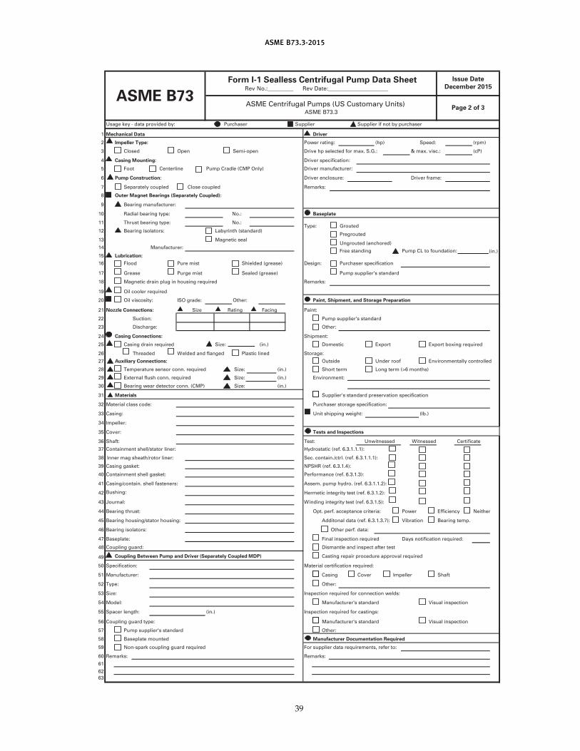
ASME B73.3-2015
Usage key - data provided by: Purchaser Supplier Supplier if not by purchaser
1 Mechanical Data Driver
2 Impeller Type: Power rating: (hp) Speed: (rpm)
3 Closed Open Semi-open Drive hp selected for max. S.G. : & max. visc.: (cP)
4 Casing Mounting: Driver specification:
5 Foot Centerline Pump Cradle (CMP Only) Driver manufacturer:
6 Driver enclosure: Driver frame:
7 Separately coupled Close coupled Remarks:
8
9 Bearing manufacturer:
1 0 Radial bearing type: No.: Baseplate
1 1 Thrust bearing type: No.:Type: Grouted
1 2 Bearing isolators: Labyrinth (standard)Pregrouted
1 3 Magnetic sealUngrouted (anchored)
1 4 Manufacturer:Free standing Pump CL to foundation:
1 5 Lubrication:
1 6 Flood Pure mist Shielded (grease) Design: Purchaser specification
1 7 Grease Purge mist Sealed (grease) Pump supplier's standard
1 8 Magnetic drain plug in housing required Remarks:
1 9 Oil cooler required
20 Oil viscosity: Other: Paint, Shipment, and Storage Preparation
21 Nozzle Connections: Paint:
22 Suction: Pump supplier's standard
23 Discharge: Other:
24 Shipment:
25 Size: ( in . ) Domestic Export Export boxing required
26 Threaded Welded and flanged Plastic l ined Storage:
27 Outside Under roof Environmentally control led
28 Size: (in . ) Short term Long term (>6 months)
29 Size: (in. ) Environment:
30 Bearing wear detector conn. (CMP) Size: (in. )
31 Materials Supplier's standard preservation specification
32 Material class code: Purchaser storage specification:
33 Casing: Unit shipping weight: ( lb.)
34 Impeller:
35 Cover: Tests and Inspections
36 Shaft: Test: Unwitnessed Witnessed Certificate
37 Containment shell/stator l iner:
38 Sec. contain./ctrl . (ref. 6.3.1 .1 .1 ):
39 Casing gasket:
40 Containment shell gasket:
41 Casing/contain. shel l fasteners: Assem. pump hydro. (ref. 6.3.1 .1 .2) :
42 Bushing: Hermetic integrity test (ref. 6.3.1 .2):
43 Winding integrity test (ref. 6.3.1 .5) :
44 Bearing thrust: Opt. perf. acceptance criteria: Power Efficiency Neither
45 Bearing housing/stator housing: Additonal data (ref. 6.3.1 .3.7): Vibration Bearing temp.
46 Bearing isolators: Other perf. data:
47 Baseplate: Final inspection required Days notification required:
48 Coupling guard: Dismantle and inspect after test
49 Coupling Between Pump and Driver (Separately Coupled MDP) Casting repair procedure approval required
50 Specification: Material certification required:
51 Manufacturer: Casing Cover Impeller Shaft
52 Type: Other:
53 Size: Inspection required for connection welds:
54 Model: Manufacturer's standard Visual inspection
55 Spacer length: ( in. ) Inspection required for castings:
56 Coupling guard type: Manufacturer's standard Visual inspection
57 Pump supplier's standard Other:
58 Baseplate mounted Manufacturer Documentation Required
59 Non-spark coupl ing guard required For supplier data requirements, refer to:
60 Remarks: Remarks:
61
62
63
ASME B73
ISO grade:
Form I-1 Sealless Centrifugal Pump Data SheetRev No.:_________ Rev Date:_____________________
Casing Connections:
Page 2 of 3ASME Centrifugal Pumps (US Customary Units)
ASME B73.3
Outer Magnet Bearings (Separately Coupled):
Auxiliary Connections:
Hydrostatic (ref. 6.3.1 .1 .1 ) :
(in. )
Temperature sensor conn. required
Rating
NPSHR (ref. 6.3.1 .4):
Journal:
Size
External flush conn. required
Performance (ref. 6.3.1 .3) :
Casing drain required
Pump Construction:
Facing
Inner mag sheath/rotor l iner:
Issue Date
December 201 5
39
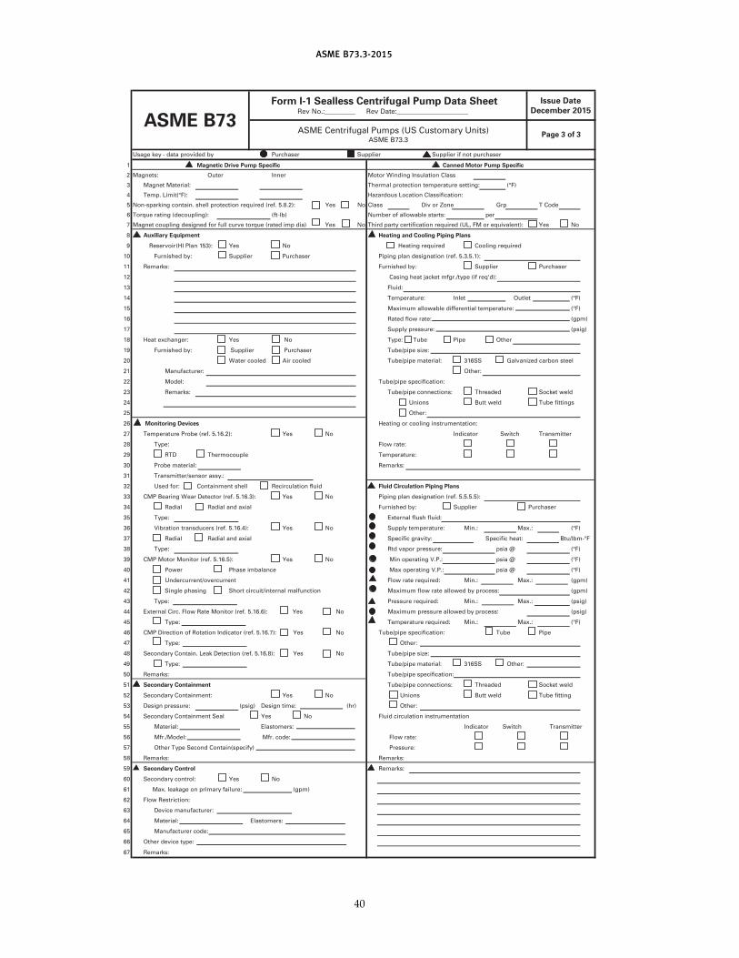
ASME B73.3-2015
Usage key - data provided by Purchaser Suppl ier Suppl ier if not purchaser
1 Magnetic Drive Pump Specific Canned Motor Pump Specific
2 Magnets: Outer Inner Motor Winding Insulation Class
3 Magnet Material : Thermal protection temperature setting: (°F)
4 Temp. Limit(°F):
5 Non-sparking contain. shel l protection required (ref. 5.8.2) : Yes No Class Div or Zone Grp T Code
6 Torque rating (decoupl ing): (ft-lb) Number of al lowable starts: per
7 Magnet coupl ing designed for fu l l curve torque (rated imp dia) Yes No Third party certification required (UL, FM or equivalent) : Yes No
8 Auxiliary Equipment
9 Yes No Heating required Cool ing required
1 0 Furnished by: Suppl ier Purchaser Piping plan designation (ref. 5.3.5.1 ) :
1 1 Remarks: Furnished by: Suppl ier Purchaser
1 2 Casing heat jacket mfgr./type ( if req'd):
1 3 Fluid:
1 4 Temperature: Inlet Outlet (°F)
1 5 Maximum al lowable differential temperature: (°F)
1 6 Rated flow rate: (gpm)
1 7 Supply pressure: (psig)
1 8 Heat exchanger: Yes No Type: Tube Pipe Other
1 9 Furnished by: Suppl ier Purchaser Tube/pipe size:
20 Water cooled Air cooled Tube/pipe material : 31 6SS Galvanized carbon steel
21 Manufacturer: Other:
22 Model : Tube/pipe specification:
23 Remarks: Tube/pipe connections: Threaded Socket weld
24 Unions Butt weld Tube fi ttings
25 Other:
26 Monitoring Devices Heating or cool ing instrumentation:
27 Temperature Probe (ref. 5.1 6.2): Yes No Indicator Switch Transmitter
28 Type: Flow rate:
29 RTD Thermocouple Temperature:
30 Probe material : Remarks:
31 Transmitter/sensor assy.:
32 Used for: Containment shel l Recirculation flu id Fluid Circulation Piping Plans
33 CMP Bearing Wear Detector (ref. 5.1 6.3): Yes No Piping plan designation (ref. 5.5.5.5):
34 Radial Radial and axial Furnished by: Suppl ier Purchaser
35 Type: External flush flu id:
36 Vibration transducers (ref. 5.1 6.4): Yes No Supply temperature: Min.: Max.: (°F)
37 Radial Radial and axial Specific gravity: Specific heat: Btu/lbm-°F
38 Type: Rtd vapor pressure: psia @ (°F)
39 CMP Motor Monitor (ref. 5.1 6.5): Yes No Min operating V.P. : psia @ (°F)
40 Power Phase imbalance Max operating V.P. : psia @ (°F)
41 Undercurrent/overcurrent Flow rate required: Min.: Max.: (gpm)
42 Single phasing Short circuit/internal malfunction Maximum flow rate al lowed by process: (gpm)
43 Type: Pressure required: Min.: Max.: (psig)
44 External Circ. Flow Rate Monitor (ref. 5.1 6.6): Yes No Maximum pressure al lowed by process: (psig)
45 Type: Temperature required: Min.: Max.: (°F)
46 CMP Direction of Rotation Indicator (ref. 5.1 6.7): Yes No Tube/pipe specification: Tube Pipe
47 Type: Other:
48 Secondary Contain. Leak Detection (ref. 5.1 6.8): Yes No Tube/pipe size:
49 Type: Tube/pipe material : 31 6SS Other:
50 Remarks: Tube/pipe specification:
51 Secondary Containment Tube/pipe connections: Threaded Socket weld
52 Secondary Containment: Yes No Unions Butt weld Tube fitting
53 Design pressure: (psig) Design time: (hr) Other:
54 Secondary Containment Seal Yes No Fluid circulation instrumentation
55 Material : Elastomers: Indicator Switch Transmitter
56 Mfr./Model : Mfr. code: Flow rate:
57 Other Type Second Contain(specify) Pressure:
58 Remarks: Remarks:
59 Remarks:
60 Secondary control : Yes No
61 Max. leakage on primary fai lure: (gpm)
62 Flow Restriction:
63 Device manufacturer:
64 Material : Elastomers:
65 Manufacturer code:
66 Other device type:
67 Remarks:
Reservoir (HI Plan 1 53):
Secondary Control
Heating and Cooling Piping Plans
ASME Centrifugal Pumps (US Customary Units)ASME B73.3
Page 3 of 3
ASME B73
Form I-1 Sealless Centrifugal Pump Data SheetRev No.:_________ Rev Date:_____________________
Hazardous Location Classification:
Issue Date
December 201 5
40
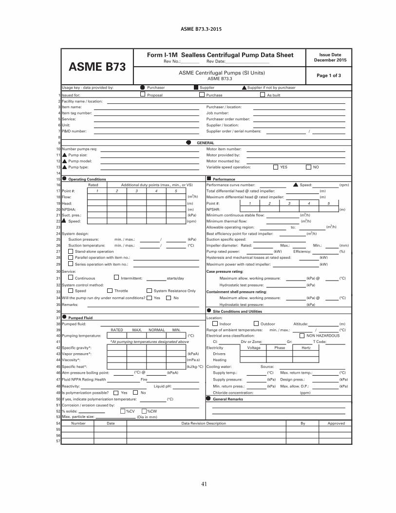
ASME B73.3-2015
Usage key - data provided by: Purchaser Supplier Supplier if not by purchaser
1 Issued for: Proposal Purchase As built
2 Facility name / location:
3 Item name: Purchaser / location:
4 Item tag number: Job number:
5 Service: Purchaser order number:
6 Unit: Supplier / location:
7 P&ID number: Supplier order / serial numbers: /
8
9
1 0 Motor item number:
1 1 Pump size: Motor provided by:
1 2 Pump model: Motor mounted by:
1 3 Pump type: Variable speed operation: YES NO
1 4
1 5 Operating Conditions Performance
1 6 Performance curve number: Speed: (rpm)
1 7 Point #: Total d ifferentia l head @ rated impeller: (m)
1 8 Flow: (m3/h) Maximum differentia l head @ rated impeller: (m)
1 9 Head: (m) Point #:
20 NPSHA: (m) NPSHR: (m)
21 Suct. pres. : (kPa) Minimum continuous stable flow:
22 Speed: (rpm) Minimum thermal flow:
23 Allowable operating region: (m3/h)
24 System design: Best efficiency point for rated impeller: (m3/h)
25 Suction pressure: min. / max. : / (kPa) Suction specific speed:
26 Suction temperature: min. / max. : / Impeller diameter: Rated: Max.: Min. : (mm)
27 Stand-alone operation Pump rated power: (kW) Efficiency: (%)
28 Parallel operation with item no. : Hysteresis and mechanical losses at rated speed: (kW)
29 Series operation with item no.: Maximum power with rated impeller: (kW)
30 Service: Case pressure rating:
31 Continuous Intermittent: starts/day Maximum allow. working pressure: (kPa) @ (°C)
32 System control method: Hydrostatic test pressure: (kPa)
33 Speed Throttle System Resistance Only Containment shell pressure rating:
34 Will the pump run dry under normal conditions? Yes No Maximum allow. working pressure: (kPa) @ (°C)
35 Remarks: Hydrostatic test pressure: (kPa)
36 Site Conditions and Utilities
37 Pumped Fluid Location:
38 Pumped flu id: Indoor Outdoor Altitude: (m)
39 Range of ambient temperatures: m in . / max.: / (°C)
40 Pumping temperature: (°C) Electrical area classification: NON HAZARDOUS
41 Cl: Div or Zone: Gr: T Code:
42 Specific gravity*: Electricity
43 Vapor pressure*: Drivers
44 Viscosity*: Heating
45 Specific heat*: (kJ /kg-°C) Cooling water: Source:
46 Atm pressure boil ing point: (°C) @ (kPaA) Supply temp.: (°C) Max. return temp.: (°C)
47 Flu id NFPA Rating: Health Fire Supply pressure: (kPa) Design press.: (kPa)
48 Reactivity: Liquid pH: Min. return press.: (kPa) Max. a llow. D.P. : (kPa)
49 Is polymerization possible? Yes No Chloride concentration: (ppm)
50 If yes, indicate polymerization temperature:
51 Corrosion / erosion caused by:
52 % solids:
53 (Dia in mm)
54 Number Date Data Revision Description By Approved
55
56
57
ASME B73Rev No. :_________ Rev Date:_____________________
ASME Centrifugal Pumps (SI Units)ASME B73.3
Page 1 of 3
GENERAL
Number pumps req:
Rated Additional duty points (max., min. , or VS)
1 2 3 4 5
1 2 3 4 5
(m3/h)
RATED MAX. NORMAL MIN.
(°C)
*At pumping temperatures designated above
General Remarks(°C)
(m3/h)
(mPa.s)
(kPaA)
HertzPhaseVoltage
to:
Form I-1M Sealless Centrifugal Pump Data Sheet
%CV %CW
Max. particle size:
Issue Date
December 201 5
41
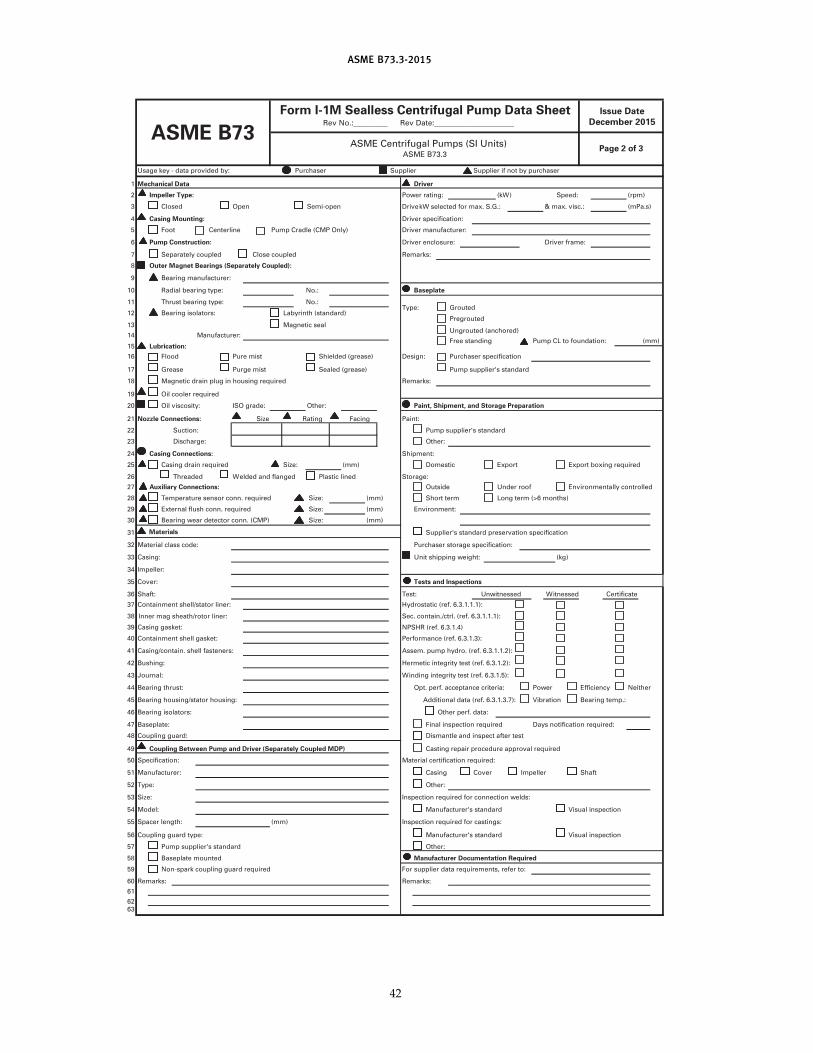
ASME B73.3-2015
Usage key - data provided by: Purchaser Supplier Supplier if not by purchaser
1 Mechanical Data Driver
2 Impeller Type: Power rating: (kW) Speed: (rpm)
3 Closed Open Semi-open & max. visc. : (mPa.s)
4 Casing Mounting: Driver specification:
5 Foot Centerl ine Pump Cradle (CMP Only) Driver manufacturer:
6 Driver enclosure: Driver frame:
7 Separately coupled Close coupled Remarks:
8
9 Bearing manufacturer:
1 0 Radial bearing type: No.: Baseplate
1 1 Thrust bearing type: No.:Type: Grouted
1 2 Bearing isolators: Labyrinth (standard)Pregrouted
1 3 Magnetic sealUngrouted (anchored)
1 4 Manufacturer:Free standing Pump CL to foundation:
1 5 Lubrication:
1 6 Flood Pure mist Shielded (grease) Design: Purchaser specification
1 7 Grease Purge mist Sealed (grease) Pump supplier's standard
1 8 Magnetic drain plug in housing required Remarks:
1 9 Oil cooler required
20 Oil viscosity: Other: Paint, Shipment, and Storage Preparation
21 Nozzle Connections: Paint:
22 Suction: Pump supplier's standard
23 Discharge: Other:
24 Shipment:
25 Size: (mm) Domestic Export Export boxing required
26 Threaded Welded and flanged Plastic l ined Storage:
27 Outside Under roof Environmentally controlled
28 Size: (mm) Short term Long term (>6 months)
29 Size: (mm) Environment:
30 Bearing wear detector conn. (CMP) Size: (mm)
31 Materials Supplier's standard preservation specification
32 Material class code: Purchaser storage specification:
33 Casing: Unit shipping weight: (kg)
34 Impeller:
35 Cover: Tests and Inspections
36 Shaft: Test: Unwitnessed Witnessed Certificate
37 Containment shell/stator l iner:
38 Sec. contain./ctrl . (ref. 6.3.1 .1 .1 ) :
39 Casing gasket:
40 Containment shell gasket:
41 Casing/contain. shell fasteners: Assem. pump hydro. (ref. 6.3.1 .1 .2) :
42 Bushing: Hermetic integrity test (ref. 6.3.1 .2) :
43 Journal : Winding integrity test (ref. 6.3.1 .5) :
44 Bearing thrust: Opt. perf. acceptance criteria: Power Efficiency Neither
45 Bearing housing/stator housing: Additional data (ref. 6.3.1 .3.7): Vibration Bearing temp.:
46 Bearing isolators: Other perf. data:
47 Baseplate: Final inspection required Days notification required:
48 Coupling guard: Dismantle and inspect after test
49 Coupling Between Pump and Driver (Separately Coupled MDP) Casting repair procedure approval required
50 Specification: Material certification required:
51 Manufacturer: Casing Cover Impel ler Shaft
52 Type: Other:
53 Size: Inspection required for connection welds:
54 Model: Manufacturer's standard Visual inspection
55 Spacer length: (mm) Inspection required for castings:
56 Coupling guard type: Manufacturer's standard Visual inspection
57 Pump supplier's standard Other:
58 Baseplate mounted Manufacturer Documentation Required
59 Non-spark coupling guard required For supplier data requirements, refer to:
60 Remarks: Remarks:
61
62
63
ASME B73Rev No.:_________ Rev Date:_____________________
ASME Centrifugal Pumps (SI Units)ASME B73.3
Page 2 of 3
Pump Construction:
Drive kW selected for max. S.G.:
Outer Magnet Bearings (Separately Coupled):
ISO grade:
(mm)
Size Rating Facing
Casing Connections:
Casing drain required
Temperature sensor conn. requ ired
External flush conn. required
Auxiliary Connections:
Hydrostatic (ref. 6.3.1 .1 .1 ) :
Inner mag sheath/rotor l iner:
NPSHR (ref. 6.3.1 .4)
Performance (ref. 6.3.1 .3) :
Issue Date
December 201 5
Form I-1M Sealless Centrifugal Pump Data Sheet
42
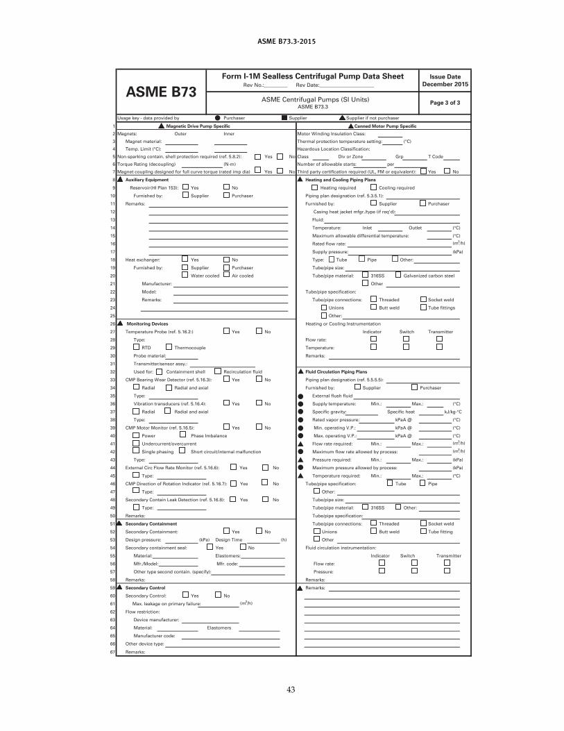
ASME B73.3-2015
Usage key - data provided by Purchaser Suppl ier Suppl ier if not purchaser
1 Magnetic Drive Pump Specific Canned Motor Pump Specific
2 Magnets: Outer Inner Motor Winding Insulation Class:
3 Magnet material : Thermal protection temperature setting: (°C)
4 Temp. Limit (°C):
5 Non-sparking contain. shel l protection required (ref. 5.8.2): Yes No Class Div or Zone Grp T Code
6 Torque Rating (decoupl ing) (N-m) Number of a l lowable starts: per
7 Magnet coupl ing designed for fu l l curve torque (rated imp dia) Yes No Third party certification required (UL, FM or equivalent) : Yes No
8 Auxiliary Equipment
9 Yes No Heating required Cool ing required
1 0 Furnished by: Suppl ier Purchaser Piping plan designation (ref. 5.3.5.1 ) :
1 1 Remarks: Furnished by: Suppl ier Purchaser
1 2 Casing heat jacket mfgr./type (i f req'd):
1 3 Fluid:
1 4 Temperature: Inlet Outlet (°C)
1 5 Maximum al lowable differential temperature: (°C)
1 6 Rated flow rate: (m3/h)
1 7 Supply pressure: (kPa)
1 8 Heat exchanger: Yes No Type: Tube Pipe Other:
1 9 Furnished by: Suppl ier Purchaser Tube/pipe size:
20 Water cooled Air cooled Tube/pipe material : 31 6SS Galvanized carbon steel
21 Manufacturer: Other
22 Model : Tube/pipe specification:
23 Remarks: Tube/pipe connections: Threaded Socket weld
24 Unions Butt weld Tube fittings
25 Other:
26 Monitoring Devices Heating or Cool ing Instrumentation
27 Temperature Probe (ref. 5.1 6.2:) Yes No Indicator Switch Transmitter
28 Type: Flow rate:
29 RTD Thermocouple Temperature:
30 Probe material : Remarks:
31 Transmitter/sensor assy.:
32 Used for: Containment shel l Recirculation flu id Fluid Circulation Piping Plans
33 CMP Bearing Wear Detector (ref. 5.1 6.3): Yes No Piping plan designation (ref. 5.5.5.5):
34 Radial Radial and axial Furnished by: Suppl ier Purchaser
35 Type: External flush flu id
36 Vibration transducers (ref. 5.1 6.4): Yes No Supply temperature: Min.: Max. : (°C)
37 Radial Radial and axial Specific gravity: Specific heat kJ/kg-°C
38 Type: Rated vapor pressure: (°C)
39 CMP Motor Monitor (ref. 5.1 6.5): Yes No Min. operating V.P. : (°C)
40 Power Phase Imbalance Max. operating V.P. : (°C)
41 Undercurrent/overcurrent Flow rate required: Min.: Max.: (m3/h)
42 Single phasing Short circuit/internal malfunction Maximum flow rate a l lowed by process: (m3/h)
43 Type: Pressure required: Min.: Max. : (kPa)
44 External Circ Flow Rate Monitor (ref. 5.1 6.6): Yes No Maximum pressure al lowed by process: (kPa)
45 Type: Temperature required: Min.: Max. : (°C)
46 CMP Direction of Rotation Indicator (ref. 5.1 6.7): Yes No Tube/pipe specification: Tube Pipe
47 Type: Other:
48 Secondary Contain Leak Detection (ref. 5.1 6.8): Yes No Tube/pipe size:
49 Type: Tube/pipe material : 31 6SS Other:
50 Remarks: Tube/pipe specification:
51 Secondary Containment Tube/pipe connections: Threaded Socket weld
52 Secondary Containment: Yes No Unions Butt weld Tube fitting
53 Design pressure: (kPa) Design Time (h) Other
54 Secondary containment seal : Yes No Fluid circulation instrumentation:
55 Material : Elastomers: Indicator Switch Transmitter
56 Mfr./Model : Mfr. code: Flow rate:
57 Other type second contain. (specify): Pressure:
58 Remarks: Remarks:
59 Remarks:
60 Secondary Control : Yes No
61 Max. leakage on primary fai lure: (m3/h)
62 Flow restriction:
63 Device manufacturer:
64 Material : Elastomers
65 Manufacturer code:
66 Other device type:
67 Remarks:
ASME B73Rev No.:_________ Rev Date:_____________________
ASME Centrifugal Pumps (SI Units)ASME B73.3
Page 3 of 3
Hazardous Location Classification:
Heating and Cooling Piping Plans
Secondary Control
Reservoir (HI Plan 1 53):
kPaA @
kPaA @
kPaA @
Issue Date
December 201 5
Form I-1M Sealless Centrifugal Pump Data Sheet
43
ASME B73.3-2015
NONMANDATORY APPENDIX AELECTRONIC DATA EXCHANGE
The information contained in pump data sheets maybe transmitted digitally rather than via a conventionaldata sheet format. This is suitable when the pump pur-chaser and supplier have systems that can process digitalinformation rather than paper-based data sheets. Directelectronic transfer can be achieved with a transfer proto-col that is adopted by both purchaser and supplier. Thistransfer protocol must also be commercially neutral ifit is to be accepted by all parties . Such a methodimproves the operating efficiencies of both parties iftheir internal data systems can import and export viathis neutral protocol.
Those interested in adopting electronic data exchange(EDE) are encouraged to reference the EDE technologyand implementation standard, HI 50.7, Electronic Data
44
Exchange for Pumping Equipment, for the digital trans-fer of centrifugal pump data. This standard providesimplementation details and examples toward adoptingEDE that are suitable for ASME B73.3 sealless centrifugalpump data. Additional interpretive information is alsoavailable at www.pumps.org/ede.
This EDE standard was developed andsupported by the Hydraulic Institute and the FiatechAutomating Equipment Information Exchange(AEX) project. Information on the EDE technology andthe AEX XML schemas is availab le online atwww.fiatech.org/projects/idim/aex.htm.
A complete listing of data fields in the ASME B73.3data sheet and their corresponding XML structures arefound in HI 50.7 or via Fiatech at www.fiatech.org.
ООО "ПромХимТех"www.promhimtech.ru