البحث المعدل بالشكل النهائي لمجلة كربلاء 1
13
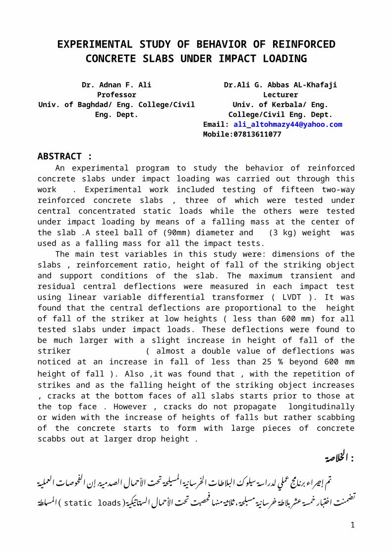
EXPERIMENTAL STUDY OF BEHAVIOR OF REINFORCED CONCRETE SLABS UNDER IMPACT LOADING Dr. Adnan F. Ali Professor Univ. of Baghdad/ Eng. College/Civil Eng. Dept. Dr.Ali G. Abbas AL-Khafaji Lecturer Univ. of Kerbala/ Eng. College/Civil Eng. Dept. Email: [email protected] Mobile:07813611077 ABSTRACT : An experimental program to study the behavior of reinforced concrete slabs under impact loading was carried out through this work . Experimental work included testing of fifteen two-way reinforced concrete slabs , three of which were tested under central concentrated static loads while the others were tested under impact loading by means of a falling mass at the center of the slab .A steel ball of (90mm) diameter and (3 kg) weight was used as a falling mass for all the impact tests. The main test variables in this study were: dimensions of the slabs , reinforcement ratio, height of fall of the striking object and support conditions of the slab. The maximum transient and residual central deflections were measured in each impact test using linear variable differential transformer ( LVDT ). It was found that the central deflections are proportional to the height of fall of the striker at low heights ( less than 600 mm) for all tested slabs under impact loads. These deflections were found to be much larger with a slight increase in height of fall of the striker ( almost a double value of deflections was noticed at an increase in fall of less than 25 % beyond 600 mm height of fall ). Also ,it was found that , with the repetition of strikes and as the falling height of the striking object increases , cracks at the bottom faces of all slabs starts prior to those at the top face . However , cracks do not propagate longitudinally or widen with the increase of heights of falls but rather scabbing of the concrete starts to form with large pieces of concrete scabbs out at larger drop height . لاصة خ ل ا: ة ي م د ص لل ا ا م ح لا ا ت ح ت حة ل س م ل ا ة ي ن ا رس خ ل ا ات لاط( ب ل ا+ وك ل س ة لدراس ي مل ع5 ج م ا رن( ب راء( ج> م ا ت. ة ي مل ع ل ا ات وص ح ف ل ا5 ن> ا حة ل س م ة ي نا رس ج ة لاط( ن رL ش ع سة م ح ار( ب ت خ ا ت ن م ض ت، ( ة ي ك ب ن ا ب س لل اا م ح لا ا ت ح ت ت ص ح فا ه من ةL لاثL نstatic loads طة ل س م ل ا) 1
description
experimental study of reinforced concrete slabs under impact loads
Transcript of البحث المعدل بالشكل النهائي لمجلة كربلاء 1
EXPERIMENTAL STUDY OF BEHAVIOR OF REINFORCED CONCRETE SLABS UNDER IMPACT LOADING
Dr. Adnan F. AliProfessor
Univ. of Baghdad/ Eng. College/Civil Eng. Dept.
Dr.Ali G. Abbas AL-KhafajiLecturer
Univ. of Kerbala/ Eng. College/Civil Eng. Dept.Email: [email protected]:07813611077
ABSTRACT :An experimental program to study the behavior of reinforced concrete slabs under impact
loading was carried out through this work . Experimental work included testing of fifteen two-way reinforced concrete slabs , three of which were tested under central concentrated static loads while the others were tested under impact loading by means of a falling mass at the center of the slab .A steel ball of (90mm) diameter and (3 kg) weight was used as a falling mass for all the impact tests.
The main test variables in this study were: dimensions of the slabs , reinforcement ratio, height of fall of the striking object and support conditions of the slab. The maximum transient and residual central deflections were measured in each impact test using linear variable differential transformer ( LVDT ). It was found that the central deflections are proportional to the height of fall of the striker at low heights ( less than 600 mm) for all tested slabs under impact loads. These deflections were found to be much larger with a slight increase in height of fall of the striker ( almost a double value of deflections was noticed at an increase in fall of less than 25 % beyond 600 mm height of fall ). Also ,it was found that , with the repetition of strikes and as the falling height of the striking object increases , cracks at the bottom faces of all slabs starts prior to those at the top face . However , cracks do not propagate longitudinally or widen with the increase of heights of falls but rather scabbing of the concrete starts to form with large pieces of concrete scabbs out at larger drop height .
: الخالصةالصدمية األحمال تحت المسلحة الخرسانية البالطات سلوك لدراسة عملي برنامج إجراء .تم
مسلحة خرسانية بالطة عشر خمسة اختبار تضمنت العملية الفحوصات تحت ،إن فحصت منها ثالثة ) الستاتيكية ) static loadsاألحمال فحصت البالطات وبقية الخرسانية البالطة مركز في المسلطة
الصدمية ( األحمال حديدية ) . impact loadsتحت كرة استخدمت البالطة مركز في ساقط ثقل بواسطةقطر ( ذات ووزن ) ( 90صلبة الصدمية ) .3ملم الفحوصات جميع في كغم
: ارتفاع التسليح، نسبة البالطات، أبعاد كانت الدراسة هذه في الرئيسية االختبار Jرات متغي إن . واالنحرافات القصوى المركزية االنحرافات قياس تم للبالطة المساند وحالة الصادم للجسم السقوط
الصدمي المتبقية الحمل تحت فحص كل الخطي ( في المتغير التفاضلي المحول ).LVDTباستخدامالمنخفضة االرتفاعات عند الساقطة الكتلة ارتفاع مع تتناسب المركزية االنحرافات قيمة بأن وTجد
من( . 600أقل االنحرافات) تلك بأن تبين الصدمية األحمال تحت المفحوصة البالطات جميع في ملم ) قيمة إلى تصل قد االنحرافات بأن لوحظ السقوط ارتفاع في طفيفة زيادة عند كثيرا اكبر تكون
من بأقل السقوط ارتفاع زيادة عند تقريبا % 25مضاعفة بعد . 600ما ( تكرار بان وTجد Z أيضا ململلبالطات السفلي الوجه في الشقوق ظهور إلى يؤدي الصادم للجسم السقوط ارتفاع وزيادة الضربات . السقوط ارتفاع زيادة عند عرضيا أو طوليا تتكاثر ال الشقوق هذه فان حال أية على العلوي الوجه قبل
الخرسانة ( في تقشر عملية تحدث السقوط ) scabbingولكن ارتفاع عند الخرسانة من قطع وتتطايرالكبير .
Keywords: impact testing , drop-weight , reinforced concrete , slabs
INTRODUCTION: Impact loading is recognized as the load resulting from collision between two bodies during a
very small interval of time . The impact load applied to a structure depends on the striker velocity,
1

the structure and the striker masses, the resulting deformations and the material properties of both bodies.
Some common examples of impact loading in the field of civil engineering are :vehicle collision with a structure , impact accidents during construction process, ships collision with offshore structures or gravity platforms , blows on concrete piles during driving , rocks falling on roof of protection shelters, aircraft collision with structure , etc. [1].
The experimental investigations on reinforced concrete slabs under impact loads are of fundamental importance because the impact load effect on these structures are complex and precise theoretical solutions are rarely available .
In this study , impact tests were used to obtain precise results on the structural behavior of
concrete slabs under impact loads.
EXPERIMENTAL WORK :
Test Specimens :
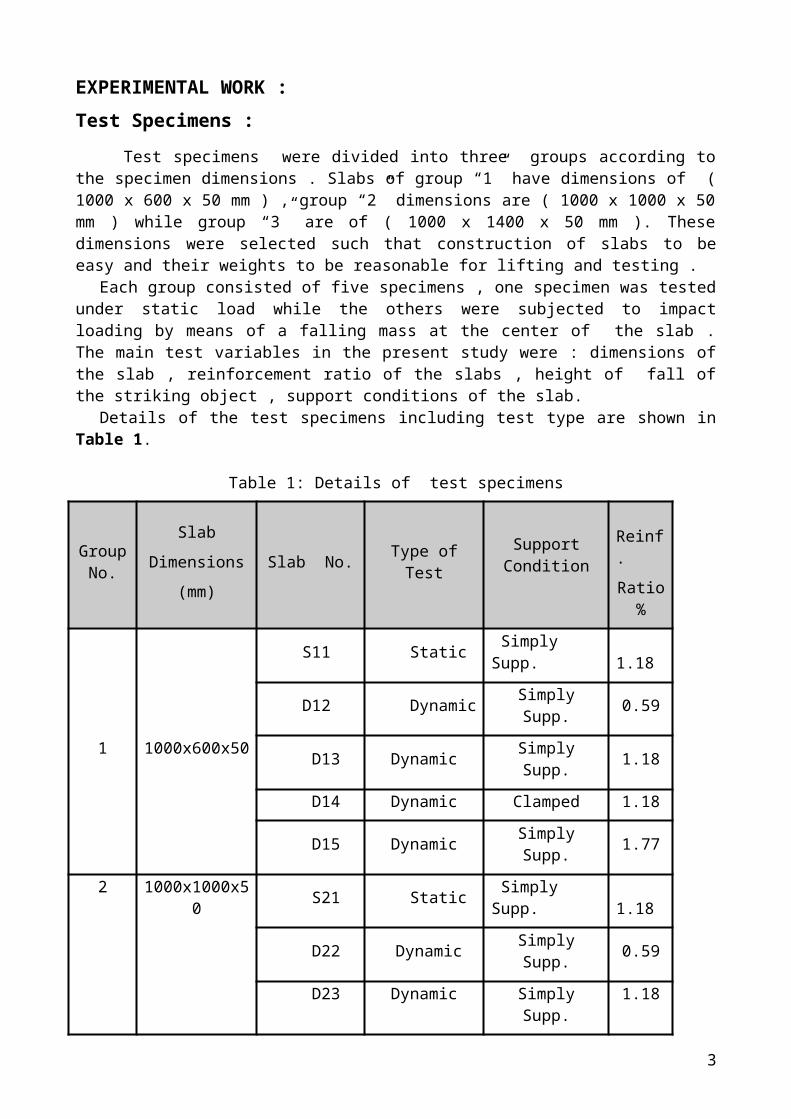
Test specimens were divided into three groups according to the specimen dimensions . Slabs of group “1” have dimensions of ( 1000 x 600 x 50 mm ) , group “2” dimensions are ( 1000 x 1000 x 50 mm ) while group “3” are of ( 1000 x 1400 x 50 mm ). These dimensions were selected such that construction of slabs to be easy and their weights to be reasonable for lifting and testing .
Each group consisted of five specimens , one specimen was tested under static load while the others were subjected to impact loading by means of a falling mass at the center of the slab . The main test variables in the present study were : dimensions of the slab , reinforcement ratio of the slabs , height of fall of the striking object , support conditions of the slab.
Details of the test specimens including test type are shown in Table 1.
Table 1: Details of test specimens
Group No.
Slab
Dimensions
(mm)
Slab No. Type of Test Support Condition
Reinf.
Ratio %
1 1000x600x50
SS11 Static Simply Supp. 1.18
SD12 Dynamic Simply Supp. 0.59
D13 Dynamic Simply Supp. 1.18
D14 Dynamic Clamped 1.18
D15 Dynamic Simply Supp. 1.77
2 1000x1000x50
S21 Static Simply Supp. 1.18
D22 Dynamic Simply Supp. 0.59
D23 Dynamic Simply Supp. 1.18
D24 Dynamic Clamped 1.18
D25 Dynamic Simply Supp. 1.77
3 1000x1400x50 S31 Static Simply Supp. 1.18
D32 Dynamic Simply Supp. 0.59
D33 Dynamic Simply Supp. 1.18
2
D34 Dynamic Clamped 1.18
D35 Dynamic Simply Supp. 1.77
Steel Reinforcement :
The concrete slabs specimens were reinforced with ( 5 mm) and ( 8 mm ) reinforcing bars as main reinforcement. Three samples for each bar size were tested for evaluation of reinforcing yield stress and ductility. Test results for the used reinforcement bars are shown in Table 2. Three different steel ratios ( ) were considered in the tested slabs. These ratios and the corresponding bar size and spacing between bars are shown in Table 3. For each specimen , the reinforcing steel ratio was taken to be identical in both directions of the slab . Details are given in
Fig.1.
*Steel reinforcement were tested at the structural laboratory in Baghdad University.
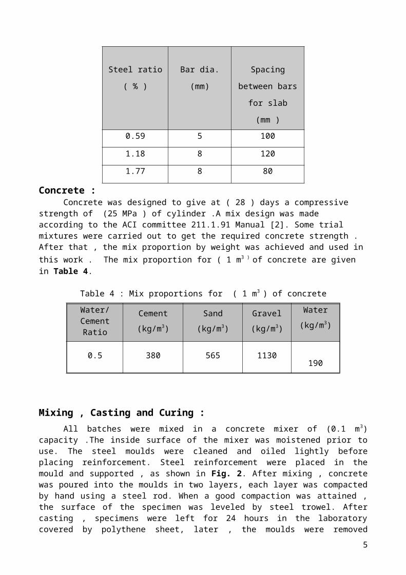
Concrete :Concrete was designed to give at ( 28 ) days a compressive strength of (25 MPa ) of
cylinder .A mix design was made according to the ACI committee 211.1.91 Manual [2]. Some trial mixtures were carried out to get the required concrete strength . After that , the mix proportion by weight was achieved and used in this work . The mix proportion for ( 1 m3 ) of concrete are given in Table 4.
3
(mm)
equivalent
Weight
(kg/m)
As
(mm2)
fy
(MPa)
fu
(MPa)
Elongation
(%)
5 4.984 0.153166 19.511 650 744 5
8 7.771 0.37233 47.43 543 670 10
Steel ratio
( % )
Bar dia. (mm) Spacing between
bars for slab (mm )
0.59 5 100
1.18 8 120
1.77 8 80
Table 2 :Test results for the used reinforcement bars*
Table 3 :Steel reinforcement details of the tested slabs
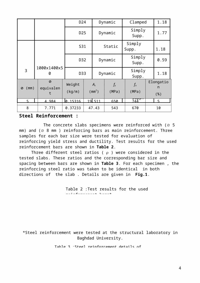
Table 4 : Mix proportions for ( 1 m3 ) of concrete
Mixing , Casting and Curing :
All batches were mixed in a concrete mixer of (0.1 m3) capacity .The inside surface of the mixer was moistened prior to use. The steel moulds were cleaned and oiled lightly before placing reinforcement. Steel reinforcement were placed in the mould and supported , as shown in Fig. 2. After mixing , concrete was poured into the moulds in two layers, each layer was compacted by hand using a steel rod. When a good compaction was attained , the surface of the specimen was leveled by steel trowel. After casting , specimens were left for 24 hours in the laboratory covered by polythene sheet, later , the moulds were removed carefully then, the specimens were marked and soaked in water for 28 days in the laboratory .
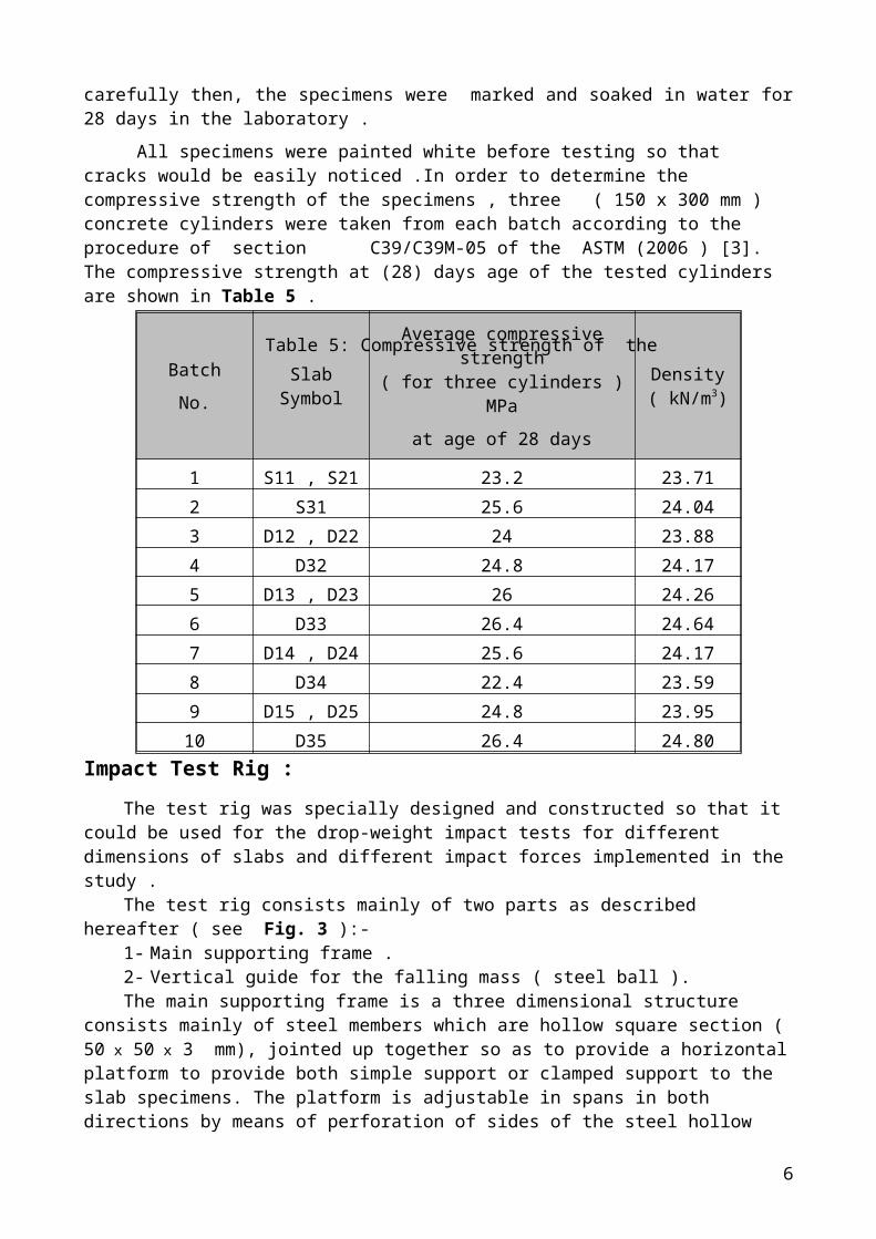
All specimens were painted white before testing so that cracks would be easily noticed .In order to determine the compressive strength of the specimens , three ( 150 x 300 mm ) concrete cylinders were taken from each batch according to the procedure of section C39/C39M-05 of the ASTM (2006 ) [3]. The compressive strength at (28) days age of the tested cylinders are shown in Table 5 .
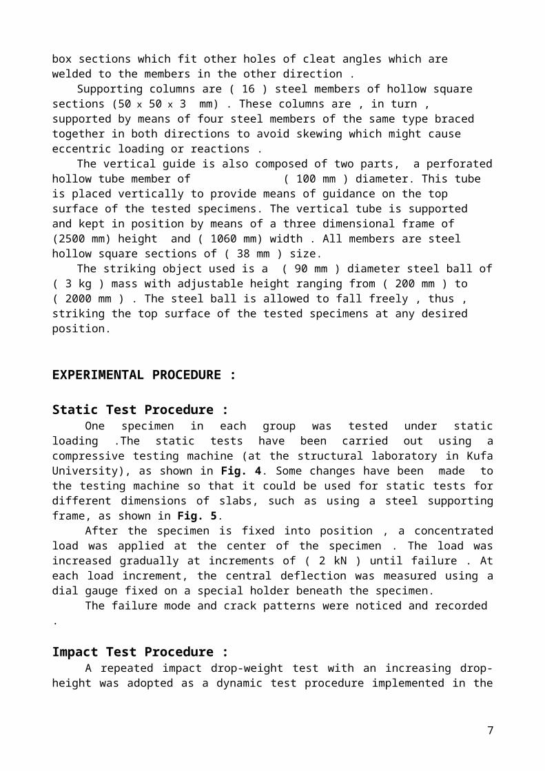
Impact Test Rig :
The test rig was specially designed and constructed so that it could be used for the drop-weight impact tests for different dimensions of slabs and different impact forces implemented in the study .
The test rig consists mainly of two parts as described hereafter ( see Fig. 3 ):-1- Main supporting frame .
4
Water/Cement Ratio
Cement
(kg/m3)
Sand
(kg/m3)
Gravel
(kg/m3)
Water
(kg/m3)
0.5 380 565 1130190
Batch
No.Slab Symbol
Average compressive strength ( for three cylinders ) MPa
at age of 28 days
Density ( kN/m3)
1 S11 , S21 23.2 23.71
2 S31 25.6 24.04
3 D12 , D22 24 23.88
4 D32 24.8 24.17
5 D13 , D23 26 24.26
6 D33 26.4 24.64
7 D14 , D24 25.6 24.17
8 D34 22.4 23.59
9 D15 , D25 24.8 23.95
10 D35 26.4 24.80
Table 5: Compressive strength of the tested cylinders
2- Vertical guide for the falling mass ( steel ball ).The main supporting frame is a three dimensional structure consists mainly of steel members
which are hollow square section ( 50 x 50 x 3 mm), jointed up together so as to provide a horizontal platform to provide both simple support or clamped support to the slab specimens. The platform is adjustable in spans in both directions by means of perforation of sides of the steel hollow box sections which fit other holes of cleat angles which are welded to the members in the other direction .
Supporting columns are ( 16 ) steel members of hollow square sections (50 x 50 x 3 mm) . These columns are , in turn , supported by means of four steel members of the same type braced together in both directions to avoid skewing which might cause eccentric loading or reactions .
The vertical guide is also composed of two parts, a perforated hollow tube member of ( 100 mm ) diameter. This tube is placed vertically to provide means of guidance on the top surface of the tested specimens. The vertical tube is supported and kept in position by means of a three dimensional frame of (2500 mm) height and ( 1060 mm) width . All members are steel hollow square sections of ( 38 mm ) size.
The striking object used is a ( 90 mm ) diameter steel ball of ( 3 kg ) mass with adjustable height ranging from ( 200 mm ) to ( 2000 mm ) . The steel ball is allowed to fall freely , thus , striking the top surface of the tested specimens at any desired position.
EXPERIMENTAL PROCEDURE :
Static Test Procedure :One specimen in each group was tested under static loading .The static tests have been
carried out using a compressive testing machine (at the structural laboratory in Kufa University), as shown in Fig. 4. Some changes have been made to the testing machine so that it could be used for static tests for different dimensions of slabs, such as using a steel supporting frame, as shown in Fig. 5.
After the specimen is fixed into position , a concentrated load was applied at the center of the specimen . The load was increased gradually at increments of ( 2 kN ) until failure . At each load increment, the central deflection was measured using a dial gauge fixed on a special holder beneath the specimen.
The failure mode and crack patterns were noticed and recorded .
Impact Test Procedure :A repeated impact drop-weight test with an increasing drop-height was adopted as a
dynamic test procedure implemented in the present work . The falling mass (steel ball ) is ( 3 kg ) in weight and of ( 90 mm ) diameter for all impact tests.
Four Specimens in each group were tested under Impact loading . The impact test conditions for each specimen were given in Table 1 . After specimen had been fixed into position , as shown in Fig. 6 , the steel ball was lifted by hand to the specific height and then released (freely) to fall at the center of the tested slab .The ball was then raised up after impact , lifting and releasing the steel ball was then repeated for larger heights until the reinforced concrete slab starts to crack and then the cracks become wide enough to be visible .For each impact test , the maximum transient and residual central deflections were measured using linear variable differential transformer ( LVDT ) and crack patterns were noticed. The (LVDT) was calibrated prior to use it in the impact tests. Two LVDTs were fixed on a magnetic holder beneath the center and quarter points of the tested slab .
EXPERIMENTAL RESULTS :
5
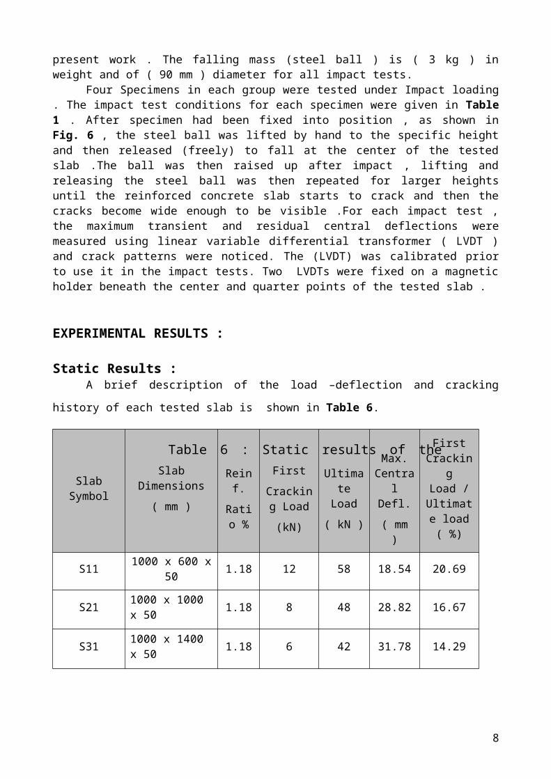
Static Results :A brief description of the load –deflection and cracking history of each tested slab is shown
in Table 6.
Slab SymbolSlab Dimensions
( mm )
Reinf.
Ratio %
First
Cracking Load
(kN)
Ultimate Load
( kN )
Max. Central Defl.
( mm )
First Cracking
Load / Ultimate load ( %)
S11 1000 x 600 x 50 1.18 12 58 18.54 20.69
S21 1000 x 1000 x 50 1.18 8 48 28.82 16.67
S31 1000 x 1400 x 50 1.18 6 42 31.78 14.29
The load-deflection curves for the three tested slabs under static loads are shown in Fig. 7.
These curves for the tested slabs can demonstrate a certain tendency in which : at early stages of loading ; slabs behave elastically with no visible cracks which explains the behavior of slab before the first cracking load . At further stage, slabs tend to shift from elastic behavior and become rather to posses a nonlinear behavior with visible minor tension cracks beyond which ( at the third stage ) yielding occurs and the slabs behave plastically.
Test results demonstrated that the ultimate load becomes smaller as the slab dimensions increase , meanwhile , the central deflection of the slabs increase as the slab dimensions increase as shown in Fig. 7.The crack patterns at the bottom face of each tested slab are shown in Fig. 8 .
Impact Results :
6
Table 6 : Static results of the tested slabs
Several selected slabs were dynamically tested under repeated impact with increasing the fall height of the striking object .
A steel ball of ( 90 mm ) diameter and (3 kg) weight was used as a falling load as planned for the impact tests .
In each impact test, the maximum transient and residual deflections at the center and quarter points of the slabs were recorded using two ( LVDT ) and digital video camera, as shown in Fig. 9.
The impact test results and some crack patterns for the tested slabs are given in Figs.(10 to 24).A complete examination of the test results which are given in the mentioned graphs reveals the following notes :
1. As a common fact , the central and quarter point deflections of each tested slabs tend to become larger as the falling height of the striker increases . The note is that , the deflections are directly proportional to the falling height at relatively low ranges of falls ( 600 – 800 mm ) , as the height of fall becomes larger , the rate of increase of deflections increases more significantly ( at an exponential relation with the height of fall ). Such a tendency might be related to the nonlinear behavior of the concrete specimens which occurs due to both sub yielding of reinforcing steel , tension cracking , crushing , and scabbing of concrete .
2. The second note is that the proportional limit ( the height of fall beyond which the fall-deflection curve becomes nonlinear ) seems to be slightly affected by changing ( increasing ) the slab dimensions . As an example , up to height of fall of (800 mm ) , the fall-deflection curve is linear in case of a slab of ( 1000 x 600 x 50 mm ) dimensions while the fall is only ( 700 mm ) for the case of a slab of ( 1000 x 1400 x 50 mm ) dimensions .
This means that crushing and scabbing are rather affected by slab thickness rather than slab dimensions which at the same time have the major role in the nonlinear behavior of the tested specimens .
3. The proportional limit ( magnitude of height of fall beyond which nonlinearity is encountered ) is not affected greatly by increasing the reinforcement ratio at the tension zone . This means that concrete crushing and scabbing dominate the causes of nonlinear behavior of slabs under impact loading .
4. However , the central deflections of the tested slabs at failure stage of impact were proved to be smaller at higher percentages of the tensile reinforcing steel ratios for given dimensions of a slab and meanwhile , the central deflection of the slab at failure stage of impact becomes larger as the slab dimensions are increased .
5. Finally , it was found that , with the repetition of strikes and as the falling height of the striking object increases , cracks at the bottom faces of all slabs starts prior to those at the top face . These cracks tend to have random shapes and directions irrespective of dimensions of slabs . However , cracks do not propagate longitudinally or widen with the increase of heights of falls but rather scabbing of the concrete starts to form with large pieces of concrete scabbs out at larger drop height .
Such a behavior is related to the tendency of axial wave which travels across the thickness of the slab and reflects at the free end ( in fact the lower surface is considered as a free end ) thus, developing tensile stresses which are doubled in magnitude after reflection .
At the same time , the top face of the slabs acts as a fixed end with respect to the wave reflecting at this face just beneath the place of the falling mass which is kept stationary at the top face of concrete . Such an action results in double compressive stresses which in turn causes spalling of concrete at the top face of the slab .
7
CONCLUSIONS :Based on the experimental results obtained in the present study , several conclusions may be
drawn and can summarized as follows :1. The ultimate load of the tested slabs under concentrated static loads decreased with in a
range of (17.2 – 27.5 % ) as the span of the slab increases by ( 60 – 125 % ) , meanwhile , the first crack load of the slabs decreases by ( 33 – 50 %) as the span of the plate increases by ( 60 – 125 % ) . Also, the actual central deflections of the tested slabs were found to be larger in magnitudes by ( 55 – 71.4 % ) as the span of the slab increases by ( 60 – 125 % ) .
2. The central deflections of the tested slabs under impact loads as obtained experimentally , tend to become larger as the falling height of the striker increases . Those deflections are directly proportional to the falling height at relatively low ranges of falls ( 600 – 800 mm ) , as the height of fall becomes larger , the rate of increase of deflections increases more significantly (at an exponential relation with the height of fall ).
3. The central deflections of the tested slabs under impact, as obtained experimentally were found to become smaller as the tensile reinforcing steel ratio increases , but the rate of the decrease in the dynamic deflection is small for high steel reinforcement ratio ( 1.77 % ) , meanwhile , the actual central deflection of the slabs becomes larger by ( 20 – 45 % ) as the span of the slab increases by ( 60 – 125 % ) .
4. The dynamic deflections of slabs with simply supported condition is larger than those deflections for slabs with clamped supports by a range of ( 45-70 % ) for the tested specimens.
5. Crack patterns at the bottom surface of the tested slabs under impact loads were found to be of a similar distribution in all slabs which have the same dimensions in spite of the difference in steel reinforcement ratio.
6. Scabbing of the concrete starts to form with large pieces of concrete scabbs out at larger drop height .
REFERENCES:1. Murtiadi, S. ,“ Behavior of High-Strength Concrete Plates under Impact Loading”, M.Sc. Thesis, Faculty of Engineering and Applied Science , Memorial University of Newfoundland, March 1999.
2. ACI Committee 211.1-91“Standard Practice for Selecting Proportions for Normal, Heavyweight, and Mass Concrete” ,ACI Manual of Concrete Practice , 1997. 3. ASTM Designation C39/C39M-05 “ Standard Test Method for Compressive Strength of Cylindrical Concrete Specimens ” , American Society for Testing and Material , West Conshohocken , Pennsylvania , 2006 , pp.2089-2094.
4. Al-Khafaji , A.G. ,“ Behavior of Reinforced Concrete Slabs under Impact”, Ph. D. Thesis, Dept.
of Civil Eng., College of Eng., University of Baghdad, 2009.
5. Hughes, G. , and Beeby , A.W. , “Investigation of the Effect of Impact Loading on Concrete Beams”, Journal of the Structural Engineer , Vol.60 B , No.3, September 1982.6. May, I.M. , Chen, Y. , Owen, D.R.J , Feng, Y.T. , and Thiele, P.J., “ Reinforced Concrete Beams under Drop-Weight Impact Loads”, Journal of Computers and Concrete , Vol.3 ,No.2, 2006, pp.1-12 .
8
9
Fig 2 : Arrangement of steel reinforcement bars
in the mould before casting.
Fig.1 : Typical steel reinforcement of a test specimen
1050
mm
1050 mm
8 @ 120 mm Ø
Fig.3 : Impact test rig
Fig. 4: Compressive testing machine Fig. 5: The static test arrangement Fig.6 : Impact test arrangement
(b) Clamped supported(a) Simply supportedFig.8 : Crack patterns of static test of slabs ( S11,S21 and S31)
(b) Slab S21(a) Slab S11 (c) Slab S31
Fig. 7: Load – deflection curves for different dimensions of slabs
0 5 10 15 20 25 30 35Central Deflection ( m m )
0
10
20
30
40
50
60
Lo
ad (
kN
)
= 1.18 %
Slab S11 ( 1000 x 600 x 50 m m )
Slab S21 ( 1000 x 1000 x 50 m m )
Slab S31 ( 1000 x 1400 x 50 m m )
Fig. 7: Load – deflection curves for different dimensions of slabs
0 5 10 15 20 25 30 35Central Deflection ( m m )
0
10
20
30
40
50
60
Lo
ad (
kN
)
= 1.18 %
Slab S11 ( 1000 x 600 x 50 m m )
Slab S21 ( 1000 x 1000 x 50 m m )
Slab S31 ( 1000 x 1400 x 50 m m )
Fig. 9 : Impact test measurementFig.11: Effect of height of impact on dynamic deflection for different support conditions for slab of dimensions (1000 600 50 mm )
0.00 0.40 0.80 1.20 1.60 2.00Max. Central Deflection ( m m )
300
400
500
600
700
800
900
1000
1100
1200
1300
1400
1500
1600
1700
1800
1900
2000
Hei
gh
t o
f th
e D
rop
( m
m )
= 1.18 %
Slab D13 ( Sim ply Supp. )
Slab D14 ( C lam ped Supp. )
Fig.10: Effect of height of impact on dynamic deflection for different steel reinforcement ratios ( ) for slab of dimensions (1000 600 50 mm )
0.00 0.40 0.80 1.20 1.60 2.00 2.40 2.80 3.20Max. Central Deflection ( m m )
300
400
500
600
700
800
900
1000
1100
1200
1300
1400
1500
1600
1700
1800
Hei
gh
t o
f th
e D
rop
( m
m )
Slab D12 ( = 0.59 % )
Slab D13 ( = 1.18 % )
Slab D15 ( =1.77 % )
Fig.13: Effect of height of impact on dynamic deflection for different steel reinforcement ratios for slab of dimensions (1000 1000 50 mm )
0.00 0.40 0.80 1.20 1.60 2.00 2.40 2.80 3.20 3.60 4.00 4.40Max. Central Deflection ( m m )
300
400
500
600
700
800
900
1000
1100
1200
1300
1400
1500
1600
1700
1800
Hei
gh
t o
f th
e D
rop
( m
m )
Slab D22 ( = 0.59 % )
Slab D23 ( = 1.18% )
Slab D25 ( = 1.77 % )
Fig.12: Effect of height of impact on residual dynamic deflection for different steel reinforcement ratios for slab of dimensions (1000 600 50 mm )
0.00 0.40 0.80 1.20 1.60 2.00Residual Central Defection ( m m )
300
400
500
600
700
800
900
1000
1100
1200
1300
1400
1500
1600
1700
1800
Hei
gh
t o
f th
e D
rop
( m
m )
Slab D12 ( = 0.59 % )
Slab D13 ( = 1.18 % )
Slab D15 ( = 1.77 % )
Fig.14 : Effect of height of impact on dynamic deflection for different support conditions for slab of dimensions (1000 1000 50 mm )
0.00 0.40 0.80 1.20 1.60 2.00 2.40 2.80Max. Central Deflection ( m m )
300
400
500
600
700
800
900
1000
1100
1200
1300
1400
1500
1600
1700
1800
1900
2000
Hei
gh
t o
f th
e D
rop
( m
m )
= 1.18 %
Slab D23 ( Sim ply Supp. )
Slab D24 ( Clam ped Supp. )
Fig. 15 : Effect of height of impact on residual dynamic deflection for different steel reinforcement ratios for slab of dimensions (1000 1000 50 mm )
0.00 0.40 0.80 1.20 1.60 2.00 2.40Residual Central Defection ( m m )
300
400
500
600
700
800
900
1000
1100
1200
1300
1400
1500
1600
1700
1800
Hei
gh
t o
f th
e D
rop
( m
m )
Slab D22 ( = 0.59 % )
Slab D23 ( = 1.18 % )
Slab D25 ( = 1.77 % )
Fig.16: Effect of height of impact on dynamicdeflection for different steel reinforcement ratios for slab of dimensions (1000 1400 50 mm )
0.0 0.4 0.8 1.2 1.6 2.0 2.4 2.8 3.2 3.6 4.0 4.4 4.8 5.2 5.6Max. Central Deflection ( m m )
300
400
500
600
700
800
900
1000
1100
1200
1300
1400
1500
1600
1700
1800
Hei
gh
t o
f th
e D
rop
( m
m )
Slab D32 ( = 0.59 % )
Slab D33 ( = 1.18 % )
Slab D35 ( = 1.77 % )
Fig.17: Effect of height of impact on dynamic deflection for different conditions for slab of dimensions (1000 1400 50 mm )
0.00 0.40 0.80 1.20 1.60 2.00 2.40 2.80 3.20Max. Central Deflection ( m m )
300
400
500
600
700
800
900
1000
1100
1200
1300
1400
1500
1600
1700
1800
1900
2000
Hei
gh
t o
f th
e D
rop
( m
m )
= 1.18 %
Slab D33 ( Sim ply Supp. )
Slab D34 (Clam ped Supp. )
Fig.18: Effect of height of impact on residualdynamic deflection for different steel reinforcementratios for slab of dimensions (1000 1400 50 mm ).
0.00 0.40 0.80 1.20 1.60 2.00 2.40 2.80 3.20Residual Central Defection ( m m )
300
400
500
600
700
800
900
1000
1100
1200
1300
1400
1500
1600
1700
1800
Hei
gh
t o
f th
e D
rop
( m
m )
Slab D32 ( = 0.59 % )
Slab D33 ( = 1.18 % )
Slab D35 ( = 1.77 % )
Fig.19: Effect of height of impact on dynamic deflection for different dimensions of slabs with steel reinforcement ratio ( = 0.59 ) .
0.0 0.5 1.0 1.5 2.0 2.5 3.0 3.5 4.0 4.5 5.0 5.5Max. Central Deflection ( m m )
300
400
500
600
700
800
900
1000
1100
1200
1300
1400
1500
1600
1700
1800
Hei
gh
t o
f th
e D
rop
( m
m )
= 0.59 %
Slab D12 ( 1000 x 600 x 50 m m )
Slab D22 ( 1000 x 1000 x 50 m m )
Slab D32 ( 1000 x 1400 x 50 m m )
Fig.20 : Effect of height of impact on dynamic deflection for different dimensions of slabs with steel reinforcement ratio ( = 1.18 % ) .
0.0 0.5 1.0 1.5 2.0 2.5 3.0 3.5Max. Central Deflection ( m m )
300
400
500
600
700
800
900
1000
1100
1200
1300
1400
1500
1600
1700
1800
Hei
gh
t o
f th
e D
rop
( m
m )
= 1.18 %
Slab D13 ( 1000 x 600 x 50 m m )
Slab D23 ( 1000 x 1000 x 50 m m )
Slab D33 ( 1000 x 1400 x 50 m m )
Fig.21: Effect of height of impact on deflection for different dimensions of slabs (clamped supp.) with steel reinforcement ratio ( = 1.18 % ) .
0.0 0.5 1.0 1.5 2.0 2.5 3.0 3.5Max. Central Deflection ( m m )
300
400
500
600
700
800
900
1000
1100
1200
1300
1400
1500
1600
1700
1800
1900
2000
Hei
gh
t o
f th
e D
rop
( m
m )
= 1.18 % [ Clam ped Supp. ]
Slab D14 ( 1000 x 600 x 50 m m )
Slab D24 ( 1000 x 1000 x 50 m m )
Slab D34 ( 1000 x 1400 x 50 m m )
Fig.22: Effect of height of impact on dynamic deflection for different dimensions of slabs with steel reinforcement ratio ( = 1.77 % ) .
0.0 0.5 1.0 1.5 2.0Max. Central Deflection ( m m )
300
400
500
600
700
800
900
1000
1100
1200
1300
1400
1500
1600
1700
1800
Hei
gh
t o
f th
e D
rop
( m
m )
= 1.77 %
Slab D15 ( 1000 x 600 x 50 mm )
Slab D25 ( 1000 x 1000 x 50 mm )
Slab D35 ( 1000 x 1400 x 50 mm )
Fig.23: Crack patterns and local failure mode of slab (D13) under impact loading (1000 600 50 mm; = 1.18 % ; simply supported; falling height = 1.8 m )
( a ) Top face
Spalling at center of top face
Cracks at corners of top face
( b ) Bottom face
Scabbing at center of bottom face
Fig. 24 : Crack patterns and local failure mode of slab (D14) under impact loading (1000 600 50 mm; = 1.18 % ;clamped supported ; falling height = 2 m )
( a ) Top face ( b) Bottom face
Scabbing at center of bottom face
Spalling at center of top face