مواصفات اعمال صيانة المباني السكنية
321
General Specification for Building Maintenance Works in Residential Buildings General Specification for Building Maintenance Works in Residential Buildings General Specification for Building Maintenance Works in Residential Buildings Prepared by Building Surveying Division, HKIS Prepared by Building Surveying Division, HKIS
-
date post
11-Sep-2014 -
Category
Health & Medicine
-
view
205 -
download
18
description
Transcript of مواصفات اعمال صيانة المباني السكنية

Gen
eral Specifi
cation for B
uild
ing M
ainten
ance W
orks in R
esiden
tial Bu
ildin
gs
General Specification for
Building Maintenance Works
in Residential Buildings
General Specification for
Building Maintenance Works
in Residential Buildings
Prepared by
Building Surveying Division, HKIS
Prepared by
Building Surveying Division, HKIS
General Specification for Building Maintenance Works in Residential Buildings
1
TABLE OF CONTENTS .........................................................................................................................1
PREFACE...............................................................................................................................................3
DISCLAIMER .........................................................................................................................................4
A1 PRELIMINARIES .........................................................................................................................5
B2 DEMOLITION / SITE CLEARANCE AND SHORING ................................................................19
B3 CONCRETE FOR MINOR WORK AND CONCRETE REPAIR .................................................27 B4 BRICKWORK AND BLOCKWORK ...........................................................................................41
B5 PLASTERING AND RENDERING .............................................................................................47
B6 TILING AND CLADDING ...........................................................................................................55
B7 PAINTING...................................................................................................................................77
B8 ROOFING, WATERPROOFING AND LEAKAGE REPAIR .......................................................93
B9 FLOOR FINISHES ...................................................................................................................109
B10 WOODWORK ..........................................................................................................................121
B11 METALWORK ..........................................................................................................................133
B12 WINDOWS ...............................................................................................................................139
B13 DOORS AND IRONMONGERY ...............................................................................................145
B14 INTERNAL FITTINGS AND FURNISHINGS ...........................................................................155
B15 GLAZING .................................................................................................................................167
B16 PLUMBING AND SANITARY FITMENTS ................................................................................177
B17 DRAINAGE ..............................................................................................................................189
B18 EXTERNAL WORKS ...............................................................................................................199
B19 SUNDRY ITEMS ......................................................................................................................205
C20 WATER SUPPLY SYSTEM ......................................................................................................219
C21 FIRE SERVICES INSTALLATION SYSTEM ...........................................................................227
C22 ELECTRICAL INSTALLATION SYSTEM ................................................................................245
C23 GAS SUPPLY SYSTEM ...........................................................................................................261
C24 LIFT INSTALLATION SYSTEM ...............................................................................................275
C25 BROADCAST RECEPTION INSTALLATION SYSTEM ..........................................................297
C26 SECURITY SYSTEM................................................................................................................ 311
LIST OF REFERENCES ....................................................................................................................319
Edition/ Date 1st Edition / Dec 2009
Author
This General Specification is produced by the Building Surveying Division (BSD) of the Hong Kong Institute of Surveyors (HKIS)
Working Group Members
Mr. Alan SinMr. Edwin TangMr. Kenneth YunMr. Nathan LeeMr. Vincent Ho
Consultant
Samson Wong & Associates Property Consultancy Limited

3
Preface
I am pleased to see the publishing of this General Specification, as this is the first General Specification (GS) in Hong Kong solely for maintenance works in residential buildings.
The main objective of this GS is to provide systematic and quality specification on works, which are commonly found in residential buildings maintenance. This GS is tailor-made for Hong Kong practice and is applicable to both high rise and low rise residential buildings. Practitioners can simply use this GS together with their own particular specification, if applicable, to suit their project requirements.
This GS consists of three Sections viz. preliminaries, building elements and building services elements. Relevant international standards of the latest version have been incorporated. To protect our living environment, specification for environmental friendly materials and energy saving devices are also included.
In order to maintain sustainability of our city after decades of development, maintenance of ageing buildings is one of the most critical issues in Hong Kong. Without a properly prepared specification, maintenance of buildings cannot be carried out effectively and efficiently. With comprehensive coverage of maintenance aspects, I believe this GS will become a useful document for building maintenance professionals in Hong Kong.
Last but not the least, I would like to take this opportunity to thank the great effort from the working group members, Mr. Edwin Tang, Mr. Nathan Lee and Mr. Vincent Ho and the convenor, Mr. Alan Sin. Without Alan’s leadership and dedicated effort together with contribution from members of working group in liaising with our consultant, Samson Wong & Associates Property Consultancy Limited and supervising the project all the way through, the GS cannot be completed successfully.
Kenneth YunChairmanBuilding Surveying Division, HKIS

4
Disclaimer
This Specification is issued for the industry to use and act as a general specification to help professional practicing in the field of building maintenance. The Specification is for reference only. Users are advised to scrutinize it and make amendments or additions as necessary to meet their own requirements and the special circumstances of each project. The specifications provided do not have either legal force or legal authority, nor are they claimed to be fully comprehensive. While the Institute endeavours to ensure the accuracy and reliability of the contents of this Specification and the information provided therein, the Institute that prepared this Specification do not guarantee their accuracy and reliability and accept no liability (whether in tort or in contract or otherwise) for any loss or damages arising from any inaccuracies or omissions in this Specification, or from the use of this Specification.

5
PreliminariesA1
General Specification A1 – Preliminaries
6
A1 PRELIMINARIES
A1.1 GENERAL
01 APPLICATION OF SPECIFICATION
This General Specification is applicable to all building maintenance works in residential buildings in connection with day-to-day maintenance work, planned maintenance work and refurbishment & renovation work unless overridden by the General Conditions of Contract, Special Conditions of Contract, Drawings, Bills of Quantities, Schedules of Rates prepared by the Employer, Particular Specifications or the instructions of the Contract Administrator.
Materials and workmanship specified in one section shall be applicable to other Sections in this
General Specification.
02 GOVERNMENT OF HONG KONG
“Government of Hong Kong” shall mean the Government of the Hong Kong Special Administrative Region (HKSARG).
03 CONTRACT ADMINISTRATOR
“Contract Administrator” shall mean the person named in the Contract Agreement who has been appointed by the Employer to supervise, on behalf of the Employer, the Contractor in carrying out of the Works.
04 BRITISH STANDARDS, EUROPEAN STANDARDS AND CODES OF PRACTICE
“British Standards”, “European Standards” and “Codes of Practice” shall be deemed to include all amendments, revisions and standards superseding the standards listed herein.
05 MANUFACTURER’S RECOMMENDATIONS
“Manufacturer’s Recommendations” shall mean the recommendations or instructions printed or in writing and produced by the manufacturer of any specified production current at the date of tender.
06 SPECIFIED
“Specified” shall mean the incorporation of a particular clause or alternatives provided with a specific reference in the Drawings, Particular Specification, Bill of Quantities or Schedules of Rates under the Contract.
07 REGULATIONS
“Regulations” shall mean any rules, Ordinance or Regulation published by the Government related to the work.
08 STATUTORY OBLIGATIONS
The Contractor shall comply with any Ordinance of Government, any instrument, rule or order made under any Ordinance of Government, or any regulation or byelaw of any local authority or of any statutory undertaker which has any jurisdiction with regard to the Works or with those systems the same are or will be connected.
09 THE SITE The site shall not be used for any purpose other than for the execution of the works.
No advertising or alike shall be allowed on site.
General Specification A1 – Preliminaries
7
10 FIRE PRECAUTIONS
Sufficient fire extinguishers shall be provided at proper locations on site and all relevant Regulations shall be complied with to prevent loss or damage from fire.
All fire hose reels shall be readily accessible and their function shall not be interrupted in the course of the works.
Contract Administrator shall be notified where it is necessary to remove the hose reels for any works. Repositioning of the fire hose shall be arranged by a Specialist Contractors. Liaison with the Specialist Contractor shall be allowed as necessary with provision of all builders attendance as required.
11 SAFETY
All Ordinances and Regulations concerning safety on the Site shall be complied with. Notice board shall be erected and relevant safety guidelines and posters, emergency contacts shall be displayed prominently on the Site throughout the construction period and removed on completion.
Attendance by Registered Safety Officer and Safety Supervisor shall be provided in accordance to relevant regulations.
Sufficient safety helmets, rubber boots, safety shoes, umbrella, protective and waterproof clothing, personal protective devices such as ear mufflers and glasses and other safety equipment where appropriate shall be provided for the use of workers, the Contract Administrator, the Contract Administrator’s representatives, and other authorised persons visiting the Site.
One set of the latest site supervision plan, safety manuals and relevant method statements shall be provided on the Site for the use of the Contract Administrator for the duration of the Contract.
Suitable site safety training shall be provided to all workers and supervisors periodically.
12 NUISANCE
All Regulations concerning the prevention of nuisance arising from vibration, noise, water, smoke, dust, accumulation of rubbish, mosquito breeding and all other causes of nuisance shall be complied with.
Mufflers or other suitable noise suppressors on all pneumatic drills, compressors and other plant which may create a noise nuisance to the general public shall be provided throughout the whole period of the Contract and extended period, if any.
Posters shall be displayed prominently on site drawing attention to the dangers of allowing the breeding of mosquitoes. Any standing water on the Site shall be treated with an approved insecticidal oil at least once per week.
All items on the Site including Constructional Plant, capable of retaining water shall be stored, covered or treated to prevent the collection of water in them.
An approved central collection point shall be provided on the Site throughout the construction period for depositing of all empty cans, oil drums, packaging and other receptacles capable of holding water and for the regular collection and removal of such articles from the Site. Burning debris, or any other matter shall not be allowed on the Site.
13 PARKING AND LOADING/ UNLOADING Availability, locations and time of use of car parking and loading/ unloading shall be agreed with
and approved by the Contract Administrator.
General Specification A1 – Preliminaries
8
14 SITE LAYOUT PLAN The Contractor shall base upon the site condition and submit a site layout plan to the Contract
Administrator for approval, with clear indication of car parking space, loading/ unloading area, material storage and dumping areas, etc.
15 EXISTING FEATURES
Written proposals for the protection of existing buildings, trees and shrubs, gates, walls and all other features of the Site which shall be retained shall be provided for the acceptance by the Contract Administrator. All features which form physical constraints to site development shall be verified on site by dimensional confirmation.
16 EXISTING SERVICES
The position of all existing utility services within the Site shall be checked and confirmed at the commencement of the Works, including locating these services by means of hand-dug trial holes.
Existing electric or telephone cables including overhead wires, gas or water mains, sewers, live drains and the like shall be protected and maintained. All necessary arrangements shall be allowed for the temporary diversion or alteration of such services to the satisfaction of the relevant authority and utility undertaking.
No works shall be commenced adjacent to existing services until the necessary diversions or alterations have been completed.
17 DRAINAGE
The Contractor shall inspect the condition of drainage system of the site before the commencement of site works and report the condition of drainage system to the Contract Administrator with report submission; or the contractor shall be responsible for any blockage, damage or other defects revealed at the completion of Works.
The Contractor shall maintain the condition of drainage system in proper manner during site works and ensure the system is free from defects upon works completion.
18 SITE ACCOMMODATION FOR CONTRACTOR
All necessary offices, mess rooms, drinking water, latrines and washing facilities and the like for all workmen engaged upon the Works including lighting, power, telephones, maintenance and cleaning shall be provided by the Contractor.
19 STORAGE SHED
The location and design of storage shed shall be agreed with the Contract Administrator. 20 ACCOMMODATION FOR WORKMEN
No workmen shall be allowed to live on the site except under special circumstance with the approval of Contract Administrator.
21 ADjOINING PROPERTIES
All adjacent lands, buildings and services which are liable to be disturbed or damaged during the execution of the Works shall be protected, shored up and in all ways supported. Adequate precautions shall be taken to prevent excavated materials encroaching onto adjoining properties. Monitor points shall be set up for controlling noise, vibration, settlement and lateral movement imposed on adjoining as directed by Contract Administrator.

General Specification A1 – Preliminaries
9
A1.2 TEMPORARY WORKS AND SERVICES
01 SECURITY
Efficient watchmen shall be provided for watching over the Site and on the Works from theft, day and night. Temporary lighting shall be provided to light up hoardings and scaffoldings. Security fence, barbed wire, or the like shall be provided to prevent unauthorized entry to the buildings.
02 SCREENS
Where work is carried out in or adjacent to existing buildings, protection shall be provided against the spread of dust and other nuisances by means of dust sheets, tarpaulins, boards and the like.
When specified, specially constructed dust-proof or sound deadening screens or such other means shall be provided as required by the Environmental Protection Department.
03 HOARDINGS AND GANTRIES
Temporary fencing, barriers, guard rails, gangways, walkways, fans and the like shall be provided for protecting the public and others during the proper execution of the Works.
When specified, hoardings or covered walkways with lighting shall be provided as required.
All materials for hoardings, gantries and covers shall be submitted for approval by the Contract Administrator.
04 SIGNBOARD
When specified, provide a project signboard or boards including sign writing in multi-coloured gloss finish over the completed board including English letter and Chinese characters, artist’s impressions or diagrammatic plans and logos. Submit draft drawings for approval before painting.
05 SCAFFOLDING
All scaffolding shall be provided with bamboo poles, fir poles, suitable brackets, wooden planks, metal foil, tarpaulin sheets and other framing and covering materials. Necessary information on scaffolding or the like in accordance with the CPFBSS and CPFMSS and Guidelines on the Design and Construction of Bamboo Scaffolds, issued by the Buildings Department shall be submitted for the consent of the Contract Administrator, taking into account of site and project conditions, 10 days prior to commencing the erection, alteration or dismantling of the Scaffold System.
All scaffolding, screens, coverings, screen framings and the like shall be properly constructed, wedged, braced, secured and maintained in accordance with best local practice. All materials shall be of good quality and of adequate strength and stability to carry the loads to be sustained.
Scaffolding shall be inspected on regular basis, with submission of inspection form and certification by competent and qualified person as per the statutory requirement.
A1.3 SPECIAL TEMPORARY WORKS (DOUBLE LAYER SCAFFOLD)
01 GENERAL
(i) Temporary double layer scaffold (hereinafter referred to as the “Scaffold System”) against the facade or perimeter of a structure or building shall be constructed, as required, with working platforms supported by two framed layers of vertical members (standards) tied by cross members (bracings, transoms) and longitudinal members (ledgers), and other ancillary members such as guard rails, toe boards, access ladders, sloping catch fans,

General Specification A1 – Preliminaries
10
safety screens, anchors, support brackets, foundations and the like.
(ii) Metal Scaffold System shall be a scaffolding system constructed, as required, with working platform adequately supported and other ancillary members including guardrails, toe boards, access ladders, slope catch-fans, safety screens, anchors, support brackets, foundation and the like; and all the structural members of the scaffolding system shall be metal.
(iii) The Scaffold System shall provide a suitable and sufficient safe means of access and workplace for carrying out work which cannot be conveniently executed from the ground or from a floor in a building, or from a ladder, etc..
(iv) The Scaffold System shall be used for all construction, alteration, repair and maintenance works. Unless otherwise specified, other alternative scaffolding may be used for screening purposes.
(v) The Contractor shall be responsible for the design, planning and co-ordination, transportation, fabrication, erection, maintenance, alteration and dismantling of the Scaffold System.
02 CODES AND STANDARDS
The design, planning and co-ordination, transportation, fabrication, erection, maintenance, alteration and dismantling of the Scaffold System shall comply with:
(i) the Factories and Industrial Undertakings Ordinance, Cap. 59; (ii) the Occupational Safety and Health Ordinance, Cap. 509; (iii) Construction Sites (Safety) Regulations, Cap. 59; (iv) Code of Practice for Bamboo Scaffolding Safety, issued by the Labour Department
(CPFBSS); (v) Code of Practice for Metal Scaffolding Safety, issued by the Labour Department
(CPFMSS); (vi) Guidance Notes on Safety at Work (Falsework - Prevention of Collapse), issued by the
Labour Department; (vii) Guidance Notes on Classification and Use of Safety Belts and their Anchorage Systems,
issued by the Labour Department; (viii) Code of Practice for the Structural Use of Steel 2005, issued by the Buildings Authority; (ix) Code of Practice on Wind Effects in Hong Kong 2004; (x) British Standard 5973 - Code of Practice for Access and Working Scaffolds and Special
Scaffold Structure in Steel; (xi) British Standard 5975 - Code of Practice for Falsework; and (xii) British Standard 1139 - Metal Scaffolding.
Reference shall also be made to the Guidelines on the Design and Construction of Bamboo Scaffolds, issued by the Buildings Department.
03 SUBMISSIONS
(i) The Contractor shall submit for the consent of the Contract Administrator the following information in accordance with the CPFBSS and CPFMSS and Guidelines on the Design and Construction of Bamboo Scaffolds, issued by the Buildings Department, taking into account site and project conditions 10 days prior to commencing the erection, alteration or dismantling of the Scaffold System:
(a) the material specifications, test certificates, place of the origin, and instructions and procedures supplied by the manufacturers of the Metal Scaffold System;
(b) the intended or current use of the Scaffold System and a method statement for the erection, alteration or dismantling of the same;
(c) the names, “substantial training” and “practical experience” of the “competent person”, the “trained workmen” and the “professional engineer” as referred to in CPFBSS and CPFMSS.
(ii) The consent of the Contract Administrator shall not relieve the Contractor of any duty or

General Specification A1 – Preliminaries
11
responsibility under the Contract.
04 DESIGN REqUIREMENTS
(i) The design and construction of the Scaffold System shall withstand a combination of the following loading situations at all stages of construction without causing bulging, distortion, overturning, collapse, settlement or damage to any portion of the structure:
(a) total weight of all members of the Scaffold System including all the associated provisions e.g. working platforms, safety nets, catch-fans etc;
(b) construction and working loads including all traffic using the Scaffold System; and (c) wind loads. (ii) For any segment of the Scaffold System exceeding 15 m in height, the whole Scaffold
System shall be designed and approved by a registered professional engineer.
05 CONSTRUCTION
(i) The Scaffold System shall be constructed and maintained in accordance with the following criteria:
(a) provide firm and adequate supports to the Scaffold System at appropriate locations. If steel brackets are used as scaffold supports, their vertical spacing shall not exceed 15 m;
(b) provide firm and adequate ties and struts for fastening the Scaffold System securely onto the structure or building. All temporary ties, fixing bolts and the like shall not be allowed to remain within the specified concrete cover and shall be cut back more than 40 mm (concrete cover for external elements) from the surface of structural concrete;
(c) provide firm and adequate longitudinal, transverse and diagonal bracings to ensure the stability of the Scaffold System;
(d) keep the space or clearance between working platforms and the structure or building as small as possible but it shall not exceed 300 mm wide;
(e) where scaffolding is provided for high rise building or structure exceeding 15 m in height, provide a protective canopy of nominal width 3600 mm at a maximum height of 6 m above ground along the edges of the structure at locations as directed by the Contract Administrator;
(f) provide safety nets comprising nylon mesh of minimum 15 core threads with grids not more than 12 mm or of similar approved type covering the entire face of the building. The safety nets shall be tautly fixed with minimum lap of 450 mm in any direction;
(g) provide a sloping catch-fan at not more than 15 m vertical intervals to give a minimum horizontal projection coverage of 1500 mm. The sloping catch-fan shall consist of timber boarding covered by a layer of galvanised metal sheeting, both of adequate thickness to capture and retain falling debris;
(h) provide access/egress to and from the walkway at appropriate locations; (i) ensure that the sloping catch-fans and safety nets remain in place until all works are
completed; (j) ensure that the Scaffold System shall not be overloaded at any time. The Scaffold
System including the sloping catch-fans, safety nets, walkways, protective canopies and the like shall be kept clear of debris; and
(k) when plastic sheet is used to cover the Scaffold System, the Scaffold System shall be reinforced to withstand strong winds. Flame retardant sheeting shall be used at locations as specified by the Contract Administrator. Obstruction of natural ventilation and lighting by sheeting should be avoided as far as possible.
(ii) During any inspection of the works, if the Contract Administrator is of the opinion that part or whole of the Scaffold System is unstable, insufficient or requires modification in the interests of safety, the Contract Administrator may, by notice in writing require the Contractor to modify the Scaffold System and the Contractor shall comply within a reasonable time.
(iii) On completion of the Works, the Contractor shall clean and make good the structure or building disturbed or damaged by the Scaffold System.

General Specification A1 – Preliminaries
12
06 MANAGEMENT
The management and procedures for safety and health on scaffolding work including safe erection/maintenance/alteration/dismantling of the Scaffold System shall comply with Section 4 and 6 of CPFBSS and CPFMSS unless otherwise approved by the Contract Administrator.
07 TECHNICAL REqUIREMENTS FOR SAFETY IN BAMBOO SCAFFOLDING
(i) When bamboo scaffolding is used for the Scaffold System, the Contractor’s attention is drawn to Section 5 of CPFBSS.
(ii) Unless otherwise approved by the Contract Administrator, all bamboo scaffolding shall be in accordance with the following drawings:
(a) For a structure or building not exceeding 15 m in height, the Scaffold System shall be in accordance with Drawing No. 3 at Annex A.
(b) For a structure or building exceeding 15 m in height, the Scaffold System shall be in accordance with Drawing No. 1, and 2 at Annex A.
(iii) Walkways shall be constructed as follows: (a) 400 mm (minimum) wide continuous walkway formed by 200 mm (minimum) x 25 mm
thick close timber boarding as referred in Figure 2 of CPFBSS, and (b) 25 mm thick toe-boards 200 mm (minimum) high at each side of walkways from which
a person or any object may fall more than a height of 2 m. (iv) No bamboo scaffolding shall be stood for use over 24 months in a construction site. All the
overdue bamboo scaffolding deemed by Contract Administrator shall be dismantled and removed off site. Erect a new bamboo scaffolding if deemed necessary.
08 TECHNICAL REqUIREMENTS FOR SAFETY IN METAL SCAFFOLDING
(i) When metal scaffolding is used for the Scaffold System, the materials, foundations and erection / maintenance / alteration / dismantling for the Scaffold System shall comply with the technical requirements for safety in metal scaffolding in Section 5 of CPFMSS.
(ii) If the Scaffold System is constructed of metal, proper equi-potential bonding and lightning protection must be provided.
09 SAFETY BARRIERS AND WARNING NOTICES FOR WORKS TO COMMON AREAS
Safety barriers clearly marked warning ‘Work in Progress’ or other wording as may be approved by the Contract Administrator shall be provided. All barriers shall be of a safe and approved design and shall be proprietary products. All other warning notices that may be required shall be provided, and there shall be ample provision of such notices on site before commencement of any works to the corridor, court yard, public areas, and points of ingress to and egress from the building. All notices shall be written clearly in contrasting colours, and shall be expressed in both English and Chinese. The size of the letters, characters and the design of the signs shall be in compliance with relevant Codes of Practice.
10 VERTICAL TRANSPORTATION OF BUILDING MATERIALS AND DEBRIS WITHIN BUILDINGS
Approval from the Contract Administrator shall be obtained for the location, design and erection of any hoisting and refuse disposal equipment. These equipment shall be maintained, adapted and modified where necessary, or as required by the Contract Administrator to suit site conditions, the same shall be cleared away when no longer required and any disturbed area shall be made good on completion of the Works.
11 WATER
All water necessary for the execution of the Works including any necessary plumbing and storage requirements relating thereto shall be provided from a source approved by the Contract Administrator.
Installation detail and routing of the water supply shall be submitted for the approval of the

General Specification A1 – Preliminaries
13
Contract Administrator prior to commencement of the installation.
12 LIGHTING AND POWER
An adequate temporary electricity supply and equipment for lighting and power for the Works and all Specialist Works where and when specified shall be provided and certified by registered electrician. Where a permanent supply is available, it may be used with the permission of the Contract Administrator subject to the cost being met by the Contractor. Separate meter shall be provided as may be required.
13 MAINTENANCE OF TEMPORARY WORKS
Temporary Works shall be maintained, altered and adapted as necessary, and shall be cleared away and made good when no longer required.
14 GONDOLAS FOR WORK TO THE EXTERIOR OF THE BUILDING
Gondolas shall be provided for access to execute work to the exterior of buildings at any height. The setting-up, adapting, subsequent shifting and positioning of the gondolas shall be arranged to suit site conditions, and the gondola shall be maintained and cleared away when no longer required or as directed by the Contract Administrator.
Any area disturbed shall be made good to match the existing. The setting up, shifting, maintenance and dismantling etc. of the gondolas shall be carried out by competent persons as required under current statutory requirements and to the satisfaction of the Contract Administrator.
Sufficient number of gondolas shall be provided for the Works at any time throughout the Contract. At the end of each day’s work or when idling the gondolas shall be lifted to such a level so that it will not interrupt the occupants of the building to enjoy normal use of the exterior of the building and the gondolas shall be well secured.
Gondolas shall be checked monthly by a recognised independent testing agency approved by the Contract Administrator. A valid certificate of testing shall be obtained and the original of the certificate shall be forwarded to the Contract Administrator for record and a copy shall be retained on site for inspection.
15 USE OF TOILETS
The Contractor shall apply to the Contract Administrator for designated toilets for use by workmen. The designated toilets shall be maintained in clean and good condition throughout the period of the Contract. Workmen shall not use toilets within the contract areas unless with the approval by the Contract Administrator.
A1.4 ADMINISTRATION AND ATTENDANCE
01 INSURANCES
Before starting work on site, documentary evidence and/or policies and receipts for the insurances required by the Conditions of Contract shall be submitted to the Contract Administrator for checking and verification.
02 INSURANCE CLAIMS
If any event occurs which may give rise to any claim or proceeding in respect of loss or damage to the Works or injury or damage to persons or property arising out of the Works, notice in writing shall be given to the Employer, the Contract Administrator and the Insurers. The Employer shall be indemnified against any loss which may be caused by failure to give such notice.
General Specification A1 – Preliminaries
14
03 SITE MEETINGS
Contractor shall attend site meetings when required by the Contract Administrator. Nominated Sub-contractors, Specialist Contractors and utilities undertaking shall be informed when their presence is required.
04 ATTENDANCE ON MATERIALS SUPPLIED BY THE EMPLOYER Where items are to be obtained from the Employer: (i) take delivery from the locations stated in Contract; (ii) load, transport to the Site, unload, check, examine, take to store and protect; (iii) take from store, distribute, hoist and fix in position; (iv) return surplus items to the locations stated in the Contract; (v) dispose all crates and containers for materials or equipment.
The Contractor shall be responsible for loss or damage to all materials supplied by the Employer.
A1.5 MATERIALS AND WORKMANSHIP
01 MATERIALS
Materials for inclusion in the permanent works shall be new unless otherwise specified.
02 qUALITY
Materials and workmanship shall generally fit for purpose and be consistent with good building practice in Hong Kong and shall comply with the relevant BS, BSEN or CP unless otherwise specified and/or approved.
03 MANUFACTURER’S RECOMMENDATIONS
Each material shall be handled, stored and fixed in accordance with manufacturer ’s recommendations. Copies of these recommendations shall be submitted to the Contract Administrator when requested before work is commenced.
04 COMPLIANCE WITH STANDARDS
When specified or when requested by the Contract Administrator, test certificates shall be provided or obtained from the manufacturer’s guarantees that materials specified are to a BS or other internationally recognized standard.
05 SPECIALIST WORK
When specified, specialist work shall be carried out by a firm approved by the Contract Administrator or whose name is included on the list of approved specialist contractors included in the Contract.
06 SPECIALIST MATERIALS
When specified, specialist materials shall be obtained from a firm approved by the Contract Administrator or whose name is included on the list of approved specialist suppliers included in the Contract.
07 SINGLE SOURCE
When a choice of manufacturer is permitted for any material, the entire quantity required to complete the work shall be either obtained from one manufacturer or, if a change in the source of supply is contemplated after deliveries of the material has begun, approval shall be obtained for such a change in the source of supply.

General Specification A1 – Preliminaries
15
08 SAMPLE OF MATERIALS
Samples of all materials required for the Works shall be submitted as the Contract Administrator may reasonably direct and do not confirm orders until approval has been obtained. Approved samples shall be kept on the Site for comparison with materials used in the Works. When there is a choice of material, colour or texture, samples shall be submitted for approval.
09 SAMPLES OF FINISHED WORK
Samples of finished work shall be made as specified or as required by the Contract Administrator and approval shall be obtained before proceeding with the work. Samples shall be retained on the Site for comparison with the completed work.
10 PROTECTION FROM WEATHER
The Works and the Specialist Works shall be covered up, protected and secured from damage by inclement weather, including providing sufficient staff, adequate plant and any other requirements necessary to ensure protection during typhoon and heavy rainstorm conditions.
11 CLEANLINESS
Materials and plant shall be stored neatly, rubbish and debris shall be removed as they accumulate, and the Site and the Works shall be kept clean and tidy. The mixing of materials or any other construction activity shall not be allowed in the public areas and must be confined to the area allocated to the Contractor for such purposes.
12 STORAGE AND DUMPING AREAS
Any storage and dumping areas allocated shall be confined with a suitable hoarding, constructed with materials of good quality and of adequate strength and stability, with lockable doors, and maintained in good condition throughout the period of the Contract. The location of the temporary storage area shall be agreed with the Contract Administrator. All materials arising from demolition and other waste materials shall be removed from public areas, i.e. corridors, staircases, etc. to an external central storage area at the end of each working day.
The arrangement of storage and dumping areas shall also be agreed with the Contract Administrator in accordance with site situation.
13 WASTE
Non-hazardous material shall be disposed of at a tip approved by EPD. All surplus hazardous materials and their containers shall be removed regularly for disposal off site in a safe and competent manner as approved by EPD and in accordance with relevant regulations. Waste transfer documentation shall be retained on site.
14 PROTECTION FROM OVERLOADING
The Works shall be protected from damage due to overloading. Details of design loads shall be obtained from the Contract Administrator.
15 TOLERANCES
Unless otherwise specified, the maximum permitted tolerances in construction shall be in accordance with BS 5606:1900.
16 SETTING OUT
The levels and dimensions of the site shall be checked against those shown on the drawings, and the results shall be recorded on a copy of the drawings. Contract Administrator shall be notified in writing when overall setting out is complete and before commencing construction.

General Specification A1 – Preliminaries
16
17 REMOVAL OF FIXING BOLTS AND TIES FOR TEMPORARY WORKS
All fixing bolts and ties for temporary works shall be removed from the building upon completion of works as far as practical and trimmed off to a depth sufficient to avoid corrosion and consequential problems to the finishes. Bolt holes formed in external walls shall be grouted properly to the satisfaction of the Contract Administrator with cement mortar of an approved mix prior to application of any surface finishes.
A1.6 ORGANISATION & SUPERVISION
01 WORKING HOURS
The working hours shall be as follows unless specifically required by the Contract Administrator under the Contract.
Working Hours: Mon.-Fri. : 8:30a.m.-5:00p.m. Sat. : 8:30a.m.-11:30a.m. Holidays : Follows the current Government practice
02 STAFF UNIFORM AND BEHAVIOUR
All staff shall wear proper uniform and staff identification cards while working on Site. No smoking, gambling or speaking in foul words etc. shall be allowed either in public areas or within domestic flats. Workers’ attitude, manner and discipline must not be offensive or oppressive. Selling of products and provision of service to the occupants of the building shall be strictly prohibited.
03 MASTER PROGRAM
The Contractor shall submit to the Contract Administrator for approval a detailed program showing his intended method, sequence, stages and order of proceeding with the Works together with the period of time estimated for each and every stage of progress.
04 PHASING OF THE WORKS
The Works shall be phased in such a way as to minimise the disturbance to the occupants of the building. All planning of works shall be submitted to the Contract Administrator for approval at least 7 days before the carrying out of the Works. Such work planning shall take the form of drawings showing the sequencing of each phase of work with time chart showing the time frame for each phase of the work.
As a minimum requirement the following guide shall apply:- (i) At no time shall more than one half of the width of any corridor, lift lobby, staircase and
staircase landing be occupied by the works. (ii) The works shall be so restricted to keep at least half the width of the corridor, staircase,
staircase landing and lift lobby free from obstruction. 05 FORECAST MONTHLY PROGRAMME
Notwithstanding the requirements to submit a master programme in accordance with other provisions of this Contract, the Contract Administrator shall be provided at the beginning of each month, a detail forecast programme of Contractor’s intended works and trades at various locations of the building for the coming month.
06 APPOINTMENT SYSTEM
The access to occupied flats shall be arranged by means of an “Appointment card system”. Appointment cards shall be disseminated to the occupants of the building at least THREE days before the works intended to be carried out to such units. Contractor shall report to Contract Administrator if the occupants of the building refuse entry after three attempts.
General Specification A1 – Preliminaries
17
07 COMPLAINT SYSTEM
The Contractor shall submit an emergency contact list with clear indicator of person-in-charge and the contact method in case of emergency.
08 TESTING AND SURVEY Compliance tests shall be carried out in accordance with the requirements under contract by
an approved accredited laboratories. The method statement, result acceptance criteria and remedial measures shall be approved by the Contract Administrator prior to execution of tests.
A1.7 REFERENCE STANDARDS
The following standards are referred to in this specification. Any standards published or revised subsequently shall take precedence over the standards provided herein.
The hierarchy of authority shall be EN standard, ISO standard, National standard.
BS5606:1990 Guide to accuracy in building

18

19
Demolition /Site ClearanceandShoring
B2

General Specification B2 – Demolition / Site Clearance and Shoring
20
B2 DEMOLITION / SITE CLEARANCE AND SHORING
B2.1 DEMOLITION / SITE CLEARANCE
01 REGULATIONS, ORDINANCES, CODES OF PRACTICE & PRACTICE NOTES All relevant legislation, Codes of Practice and Practice Notes in connection with demolition
works shall be complied with. Particular attention is drawn to the following: (i) Building (Demolition Works) Regulations (ii) Construction Sites (Safety) Regulations (iii) Noise Control Ordinance (iv) Air Pollution Control (Amendment) Ordinance (v) Building Planning Regulations (vi) The Factories and Industrial Undertakings Ordinance (vii) The Factories and Industrial Undertakings (Lifting Appliances and Lifting Gear)
Regulations (viii) The Factories and Industrial Undertakings (Noise at Work) Regulations (ix) The Factories and Industrial Undertakings (Safety Officers and Safety Supervisors)
Regulations (x) Air Pollution Control (Construction Dust) Regulations (xi) The British Standard Code of Practice for Demolition: BS 6187:2000 (xii) The prevailing Buildings Department Practice Notes for Authorised Persons and
Registered Structural Engineers (xiii) The prevailing Buildings Department Practice Notes for Registered Contractors
02 SURVEY
Before starting work, a survey shall be carried out and a report and method statement covering all relevant matters listed below shall be submitted:
(i) Condition and demolition methods of the structure(s). (ii) Removal methods of any hazardous materials. (iii) Type and location of adjoining or surrounding premises which may be adversely affected
by the works. (iv) Identification and location of services.
03 BENCH MARKS
Any bench marks and other survey information found shall be reported. No bench marks shall be removed or destroyed unless instructed.
04 LOCATION OF SERVICES The positions of services affected by the work shall be located and marked. The location and
marking of the positions of mains services shall be verified with the appropriate authorities.
05 DISCONNECTION OF SERVICES Before starting demolition, the disconnection of services and removal of fittings and equipment
shall be arranged with the appropriate authorities.
06 DISCONNECTION BY THE EMPLOYER If disconnection of services is to be carried out by the Employer, the disconnection and removal
of fittings and equipment shall be carried out before starting demolition.
07 DISCONNECTION OF DRAINS All disused drain connections shall be located, disconnected and sealed within the site to
approval.
General Specification B2 – Demolition / Site Clearance and Shoring
21
08 DRAINS IN USE Drains and fittings still in use shall be protected and kept free of debris at all times. Any
damage arising from demolition work shall be made good and left clean and in working order at completion.
09 BYPASS CONNECTIONS Bypass connections shall be provided as necessary to maintain continuity of services to
occupied areas of the same and adjoining properties. Adequate notice shall be given to occupiers if shutdown is necessary.
10 SERVICES WHICH ARE TO REMAIN The Contract Administrator and relevant utility companies or government authorities shall
be notified of any damage. All arrangements for protection and upkeep shall be made to the satisfaction of the Contract Administrator and relevant utility companies or government authorities. The Contractor shall bear any costs arising from the works.
11 PRECAUTIONARY MEASURES When specified, the demolition works and/or alteration works shall be enclosed with closed
boarding or fine mesh screen of sufficient strength to protect the adjoining areas from disturbance and falling debris, etc.
Inconvenience to occupants, adjoining owners and the public shall be as little as possible. Approved dust control methods shall be carried out to prevent dust arising from the works.
12 WORKMANSHIP Structure(s) shall be demolished in accordance with BS 6187:2000 and approved method
statement. Operatives must be appropriately skilled and experienced for the type of work and hold or be training to obtain relevant CITA Certificates of Competence.
Site staff responsible for supervision and control of the work shall be experienced in the
assessment of the risks involved and in the methods of demolition to be used.
13 SITE HAZARDS Fire or explosion caused by gas or vapour shall be prevented. Dust shall be reduced by
periodically spraying with water. Adequate precautions shall be taken to protect site operatives and the general public from dangerous fumes and dust arising during the course of the works.
14 ADjOINING PROPERTY Adequate temporary support and protection to adjoining property shall be provided at each
stage. Damage to adjoining property shall be prevented and no unnecessary or unstable projections shall be left. Support to foundations of adjoining property shall not be disturbed.
Any defects exposed or becoming apparent in adjoining property shall be reported. Any damage
caused to adjoining property shall be promptly repaired.
15 STRUCTURE(S) TO BE RETAINED Parts of existing structure(s) which are to be kept in place shall be adequately protected.
Debris shall not overload any part of the structure which is not to be demolished.
General Specification B2 – Demolition / Site Clearance and Shoring
22
16 PARTLY DEMOLISHED STRUCTURE(S) Partly demolished structure(s) shall be kept in a stable condition, with adequate temporary
support at each stage to prevent risk of uncontrolled collapse. Debris shall not overload scaffolding platforms. Access of unauthorised persons to partly demolished structure(s) shall be prevented. Partly demolished structures shall be left safe outside working hours.
17 DANGEROUS OPENINGS Dangerous openings shall be illuminated and protected as necessary.
18 COMPLETION All debris shall be cleared away all debris and the site shall be left tidy on completion.
19 OWNERSHIP Components and materials arising from the demolition work shall become the property of the
Contractor except where otherwise provided, and shall be removed from site as work proceeds.
B2.2 ASBESTOS-CONTAINING MATERIALS (ACM)
01 SAMPLING AND ANALYSIS Bulk samples of suspected asbestos-containing materials and analysis shall be carried out by
an approved laboratory to verify the presence of asbestos, and to determine the content and the type of asbestos.
Full depth of the insulation materials shall be taken from its outer surface to the base structure for sampling. When specified, two additional side by side quality control samples shall be taken and analysed by another approved laboratory.
02 ASBESTOS REMOVAL
Asbestos-containing materials shall be removed by an approved registered asbestos contractor prior to commencement of general demolition works to avoid contamination of debris arising from the demolitions.
03 ASBESTOS ABATEMENT PLAN AND METHOD STATEMENT Where an asbestos abatement plan has been prepared, the registered asbestos consultant
appointed shall supervise the implementation of the plan. Where the submission of an asbestos abatement plan is not required, the Contractor shall submit, before commencement of the removal work, a detailed method statement to the Contract Administrator for approval, which shall include a detailed work programme, sketches showing the containments, air locks, air movers and scaffolding as required. Contingency measures of safety and escape access shall be maintained in case of an emergency such as fire and accident, etc.
04 GLOVE BAG METHOD The use of glove bag method for the removal of asbestos-containing materials shall be approved
by the Contract Administrator.
05 SITE SUPERVISION A full time site supervisor, experienced and competent in asbestos work, shall be stationed at
the work site.

General Specification B2 – Demolition / Site Clearance and Shoring
23
06 WARNING SIGNS Proper and publicly visible warning signs shall be provided to read, “Danger - Asbestos, No
Unauthorized Entry”, in block capital letters and Chinese characters.
07 MINIMISATION OF FIBRE RELEASE No power tools shall be used directly on asbestos-containing materials.
Asbestos materials shall be wetted prior to stripping/removal and shall be mist-sprayed with amended water during stripping.
Asbestos waste shall be collected in approved waste containers as soon as it is produced.
Debris/dust generated shall be removed with high efficiency particulate absolute vacuum cleaner which shall be positioned next to the source of fibre generation.
When entering or leaving the contaminated work area, a strict changing and decontamination routine must be followed by all personnel.
08 WASTE DISPOSAL Asbestos-containing waste generated from the removal work shall be properly disposed of in
accordance with the requirements of the “Code of Practice on Handling, Transportation and Disposal of Asbestos Wastes” published by the Environmental Protection Department.
Notification shall be given to the Environmental Protection Department at least ten days before the scheduled disposal of asbestos waste and a duly stamped trip ticket shall be submitted to the Contract Administrator for confirmation of disposal.
Water contaminated with asbestos shall be filtered first before being discharged into soil drains.
09 AIR MONITORING
Asbestos removal shall be closely monitored by air sampling and an analysis of the air-borne fibres in conjunction with the removal work undertaken by an approved laboratory.
A reading of 0.01 fibre/ml or less shall be required in the penultimate and final air sample analysis.
10 STORAGE OF WASTE
Double-bagged asbestos waste shall be numbered with a waterproof ink pen and stored either in a designated weatherproof holding area within the Site or in a secured lockable area outside the contaminated works area, with either location to be agreed on site.
11 REGULATIONS, ORDINANCES AND CODES OF PRACTICE
All relevant legislation and Codes of Practice in connection with asbestos removal works shall be complied with. Particular attention shall be drawn to the following:
(i) Factories and Industrial Undertakings (Asbestos) Regulations. (ii) Air Pollution Control Ordinance. (iii) Air Pollution Control (Amendment) Ordinance. (iv) Air Pollution Control (Asbestos) (Administration) Regulations. (v) Factories and Industrial Undertakings (Asbestos) (Approval of Respiratory Protective
Equipment) Notice. (vi) Code of Practice on Handling, Transportation and Disposal of Asbestos Waste,
Environmental Protection Department, 1993. (vii) Code of Practice on Asbestos Work using Full Containment or Mini Containment methods,
General Specification B2 – Demolition / Site Clearance and Shoring
24
Environmental Protection Department, Hong Kong. (viii) Code of Practice on Safe Handling of Low Risk Asbestos-Containing Materials,
Environmental Protection Department, Hong Kong. (ix) Code of Practice on Safe Handling of In-situ Asbestos-Containing Materials,
Environmental Protection Department, Hong Kong. (x) Code of Practice on Asbestos Work using Glove Bag Method, Environmental Protection
Department, Hong Kong. (xi) Code of Practice - Safety and Health at Work with Asbestos, Labour Department, Hong
Kong.
B2.3 SHORING
01 GENERAL
All available information shall be examined before starting work. Survey the structure, site and surrounding area shall be surveyed. Method statements shall be submitted to the Contract Administrator covering any relevant matters raised in the design brief. All statutory notices shall be given and licenses shall be obtained.
02 EXTENT OF SUPPORT WORK
Support systems shall be designed in accordance with the design brief, BS 5975:2008. Before starting work, detailed proposals including drawings and calculations for all systems shall
be submitted to the Contract Administrator, and any amendments proposed shall be resolved. Contractor shall accept responsibility for the adequacy and stability of support systems and
thereby the integrity of supported structure for the period from commencement of erection to completion of dismantling of support systems.
03 CORROSION PROTECTION
Before starting work, corrosion protection proposals for support systems shall be submitted to the Contract Administrator.
04 ERECTING SUPPORT SYSTEMS
Positions of existing and new services which may be affected by support systems shall be located. Any necessary temporary diversions shall be provided.
Excessive loadings from foundations of support systems shall be prevented from being imposed
onto foundations of structure to be kept in place. Support systems shall be erected and connected to structure to be kept in place taking all
necessary precautions to prevent damage, and taking due account of movement of structure which may occur before, during and after demolition.
Any damage caused to adjoining property by erection or connection of support systems shall
be promptly repaired, and shall be made good to ensure safety, stability, weather protection and security.
Any damage caused to retained facades by erection or connection of support systems shall
be reported to the Contract Administrator. Methods of repair shall be agreed with the Contract Administrator.
Support systems shall be checked at agreed stages during erection for compliance with design
proposals.
General Specification B2 – Demolition / Site Clearance and Shoring
25
05 LOADING SUPPORT SYSTEMS
When support systems are erected and all connections are made to structure to be kept in place, Contract Administrator shall be informed and any required permission to load systems shall be obtained.
06 MAINTAINING SUPPORT SYSTEMS
Safe access and safe places of work shall be provided in the support systems for inspection and maintenance.
Support systems shall be inspected and maintained regularly, ties, wedges, connections, corrosion protection, etc. shall be made good as necessary.
Support systems shall be adequately protected from impact damage by vehicles, plant and site operations.
Access of unauthorised persons onto support systems shall be prevented. Support system shall be left safe outside working hours.
07 DISMANTLING SUPPORT SYSTEMS
When all permanent connections between supported structure and new construction have been made, the Contract Administrator shall be informed and any required permission to disconnect and dismantle support systems shall be obtained.
08 MAKING GOOD
Any connection holes made in the structure kept in place shall be repaired.
09 COMPLETION All support systems shall be cleared away and the site and any working areas beyond the site
boundary shall be left in a tidy condition on completion.

26
27
ConcreteforMinorWorkandConcrete Repair
B3
General Specification B3 – Concrete for Minor Work and Concrete Repair
28
B3 CONCRETE FOR MINOR WORK AND CONCRETE REPAIR
B3.1 MATERIALS
01 FORMWORK
Formwork shall be timber, metal, plastic or other materials, which produce the specified finish. Materials used as formers for profiled formwork, chamfers, splays, rebates and other features shall be such that they produce the same finish as the main formwork.
Plywood for formwork shall have a close, uniform grain and the edges shall be sealed with barrier paint, polyurethane varnish or other impermeable materials. Plywood sheathing to formwork shall not be subjected to more than nine uses, irrespective of the use of one or both faces of such sheathing.
02 RELEASE AGENTS
Release agents shall be of a type that shall not stain or colour the concrete and which shall not affect the bond between the concrete and subsequent coverings.
03 REINFORCEMENT
Steel reinforcement shall be plain round steel or deformed high yield steel bars to CS2 or hard drawn steel wire fabric to BS 4483:2005.
Obtain steel reinforcement from suppliers who shall be able to produce certificates for each consignment of steel reinforcement supplied to site. The certificates to be submitted shall be in accordance with the class of reinforcement delivered to site, all as detailed in CS2.
04 CEMENT
Portland cement shall comply with BSEN 197-1: 2000 (Type CEM I). Strength Class of cement used in structural concrete shall be 52.5 N, unless otherwise approved by the Contract Administrator.
05 AGGREGATE
Coarse aggregate of 20 mm nominal maximum size shall be provided. Fine aggregate with grading lying within the limits of Grading C and M or crushed stone fines shall be provided as tabulated below.
Grading of fine aggregate
Sieve size Percentage by weight passing BS sieve Overall limits Additional limits for grading Grading C Grading M Grading F 10.00mm 100 - - - 5.00mm 89-100 - - - 2.36mm 60-100 60-100 60-100 80-100 1.18mm 30-100 30-90 45-100 70-100 600μm 15-100 15-54 25-80 55-100 300μm 5-70 5-40 5-48 5-70 150μm 0-15 - - -
General Specification B3 – Concrete for Minor Work and Concrete Repair
29
Grading of crushed stone fines
Sieve size Percentage by weight passing BS sieve 10.0 mm 100
5.0 mm 85-100 2.36 mm 60-87 1.18 mm 40-67 600 μm 20-50 300 μm 5-35 150 μm 0-20
Aggregates, if so instructed by the Contract Administrator, shall be subjected to sieve analyses to BS 812.
06 WATER
Water for concreting shall be clean and uncontaminated potable water from Government main supply or any other approved source. If taken from a source other than Government main supply, it shall be tested in accordance with BS EN 1008:2002 when required by the Contract Administrator.
07 ADMIXTURES
Admixtures shall comply with BS EN 480-4:2005; BS EN 480-2:2006; BS EN 480-5:2005; BS EN 480-6:2005; BS EN 480-10:1997; BS EN 480-8:1997; BS EN 934-2:2009; BS EN 480-1:2006; BS EN 480-12:2005; BS EN 480-11:2005; BS EN 934-6:2001; BS EN 934-2:2009 and shall be used strictly in accordance with the manufacturer’s recommendations.
08 TIE BARS Tie bars shall comply with BS 4449:2005+A2:2009 and shall be clean and free from loose
millscale, loose rust, ice, oil and other deleterious substances.
09 MESH TIE STRIPS Mesh tie strips shall comply with BS 4483:2005, and shall be clean and free from loose
millscale, loose rust, ice, oil and other deleterious substances.
10 DOWEL BARS Dowel bars shall comply with BS 4449:2005+A2:2009, and shall be perfectly straight, with
sawn (not sheared) ends.
B3.2 WORKMANSHIP
B3.2.1 FORMWORK
01 FORMWORK BELOW GROUND Vertical faces of strip footings, bases and slabs may be cast against faces of excavation,
provided the faces are sufficiently accurate and stable and adequate measures are taken to prevent contamination of concrete.
02 GENERAL FORMWORK Formwork shall be constructed accurately and robustly to produce finished concrete to the
required dimensions. Formed surfaces shall be free from twist and bow, all intersections, lines and angles being square, plumb and true.
Formwork shall be constructed (including joints between forms and completed work) to prevent
General Specification B3 – Concrete for Minor Work and Concrete Repair
30
loss of grout, using seals when necessary. Formwork shall be secured tight against adjacent concrete to prevent formation of steps.
Inserts or box out shall be fixed as required in correct positions before placing concrete. All
holes and chases shall be formed. Cutting hardened concrete shall not be proceeded without approval.
B3.2.2 REINFORCEMENT FOR IN-SITU CONCRETE
01 CLEANLINESS OF REINFORCEMENT
At time of placing concrete, reinforcement shall be clean and free of corrosive pitting, loose millscale, loose rust, ice and substances which may adversely affect the reinforcement, concrete, or bond between the two.
02 LAPS IN NOMINAL BAR REINFORCEMENT Laps shall be not less than 300 mm.
03 LAPS IN FABRIC REINFORCEMENT
Laps shall be not less than 250 mm.
04 FIXING REINFORCEMENT Where ground bearing slabs are reinforced with a single layer of fabric in the upper part of
the slab, the fabric may be placed in position on top of the first compacted layer of concrete, followed by the top layer of concrete, placed within 2 hours of the first layer.
In all other cases, reinforcement shall be fixed before the concrete is placed. Suitable spacers
at not more than 1 m centres or closer spacing as necessary shall be provided to support in position and maintain the specified cover.
Reinforcement shall be fixed adequately, using tying wire, which must not intrude into the
concrete cover.
B3.2.3 IN-SITU CONCRETE
01 SUBSTITUTION OF STANDARD FOR DESIGNATED MIXES
Where appropriate, Standard mix(es) to BS EN 206-1:2000 may be permitted in substitution for specified Designated mixes in accordance with BS EN 206-1:2000 in each case subject to approval.
If Standard mixes are made on site, it shall comply with BS 8000: Section 2.1, Subsections 2, 3 and 4.
02 UNDERLAY Before concreting on hardcore or other absorbent substrates, building paper to BS 1521:1972,
Class B or polythene sheet, 250 microns thick shall be laid with lap edges 150 mm.
03 PLACING AND COMPACTING OF CONCRETE At time of placing, all surfaces on which concrete is to be placed shall be clean, with no debris,
tying wire clippings, fastenings or free water. Concrete shall be placed while sufficiently plastic for full compaction. Water shall not be added
and mixes shall not be retempered. The temperature of concrete at time of placing must be not less than 5oC. Concrete shall not be placed against frozen or frost covered surfaces.
General Specification B3 – Concrete for Minor Work and Concrete Repair
31
Compacting shall be to full depth (until air bubbles cease to appear on the top surface), especially around reinforcement, cast-in accessories, into corners of formwork and at joints.
04 CURING AND PROTECTING OF CONCRETE
Surface evaporation from concrete surfaces shall be avoided as specified below by covering with polythene sheeting as soon as practicable after completion of placing and compacting, removing only to permit any finishing operations and replacing immediately thereafter.
Surfaces which will be exposed to frost, and wearing surfaces of floors and pavements,
regardless of weather conditions: not less than 10 days. Other structural concrete surfaces: not less than 5 days.
Concrete shall be adequately protected from shock, indentation and physical damage.
B3.2.4 WORKED FINISHES TO IN-SITU CONCRETE
01 TIMING
All finishing operations shall be carried out at optimum times in relation to the setting and hardening of the concrete. Wetting surfaces of concrete or sprinkling cement on to surface to assist surface working shall not be allowed.
02 SMOOTH FLOATED FINISH
A hand float, skip float or power float shall be used to give an even surface with no ridges or steps.
03 TROWELLED FINISH
Concrete shall be floated to an even surface with no ridges or steps, then immediately be commenced with curing as specified.
When the concrete is suitably stiff, it shall be hand or power trowelled to give a uniform smooth
but not polished surface, free from trowel marks and other blemishes, and suitable to receive the specified flooring materials. Specified curing shall be resumed without delay.
If, because of inadequate finishing or protection, the surface of the concrete is not suitable to
receive the specified flooring materials, it must be made good by application of a smoothing compound.
B3.2.5 DESIGNED jOINTS IN IN-SITU CONCRETE
01 ACCURACY
All joints shall be accurately located, straight and well-aligned, and truly vertical or horizontal or parallel with the setting out lines of the building.
02 CONSTRUCTION / MOVEMENT jOINTS Joints shall be formed accurately to detail and in locations shown on the drawings. If
modifications to any joint design or location are necessary on site, revisions shall be agreed with Contract Administrator before proceeding.
Concrete shall not be allowed to enter any gaps or voids in the formwork or to render the
movement joints ineffective. Concrete shall not be allowed to impregnate or penetrate any materials used as compressible
joint fillers.

General Specification B3 – Concrete for Minor Work and Concrete Repair
32
Concrete shall not be placed simultaneously on both sides of movement joints.
03 FORMED jOINTS Joints shall be constructed using rigid, grout-tight side forms or stop ends designed to
accommodate projecting bars or fabric without temporary bending or displacement.
04 ROUGHENING OF CONSTRUCTION jOINT FACES Surface of construction joints shall be brushed and sprayed while concrete is still green to
leave a thoroughly roughened exposed aggregate finish.
05 FLEXIBLE WATERSTOPS All junctions and angles must be formed with the junction pieces recommended by the
manufacturer. Straight butt joints shall be made on site as recommended by the manufacturer. Waterstops shall be maintained in correct position while concrete is placed. Concrete around
waterstops shall be fully compacted to ensure that no voids or porous areas remain.
06 TIE BARS Tie bars shall be fixed securely at the stated centres, at the required depth and centred on the
joints.
07 MESH TIE STRIPS Mesh tie strips shall be fixed securely at the required depth with the width of the strip centred
on the joint.
08 DOWEL BARS Half of each bar shall be coated with a suitable proprietary debonding compound or fitted with
a suitable plastics sleeve. Bars shall be fixed securely at the required depth, perfectly level, at right angles to and centred
on the joint. At expansion joints, an approved type of cap incorporating not less than 20 mm of compressible
material shall be fitted to debonded ends of all bars.
B3.3 CONCRETE REPAIR
B3.3.1 MATERIALS
01 PRIMERS
The primer shall be in accordance with the recommendations/ instructions of the manufacturer of the approved proprietary repair mortar.
(i) Rust Inhibitors: unless otherwise approved, rust inhibitors shall contain titanium dioxide as the pigment in a modified aliphatic was binder.
(ii) Cement Based Reinforcement Primer shall be approved polymer modified cement based corrosion resistance primers.
(iii) Epoxy Based Reinforcement Primers shall be approved two components epoxy resin supplied in pre-weighed quantities. The primer shall be used before the expiry of its shelf life and pot life. It shall also have a pot life suitable for repair application as in the opinion of the Contract Administrator.
Where zinc rich primers are required they shall contain zinc dust as pigment in epoxy resin binder.

General Specification B3 – Concrete for Minor Work and Concrete Repair
33
02 REINFORCEMENT
Dowel bars and replacement reinforcements shall comply in all aspects with the Specifications.
03 BOND COATS
It shall be all in accordance with the recommendations/instructions of the manufacturer of the proprietary repair mortar.
(i) Cement based bond coats shall be approved blend of cementitious materials incorporating a polymer emulsion. The bond coat shall be all in accordance with the recommendations/instructions of the manufacturer of the approved proprietary repair mortar.
(ii) Epoxy based bond coats shall be approved two component materials based on epoxy resin. It shall be supplied in pre-weighed quantities and shall be used before the expiry of its shelf and pot life. It shall also have a pot life suitable for repair application as in the opinion of the Contract Administrator.
(iii) Acrylic based bond coats shall be approved single component materials based on an acrylic polymer or copolymer emulsion.
04 CEMENT
Unless otherwise specified, it shall be ordinary Portland cement complying with BS EN 197-1:2000. The quality, delivery, storage and testing of cement shall comply in all aspects with the Specifications.
05 SAND
For mortar, it shall be medium grade natural sand complying with BS EN 12620:2002+A1:2008 and shall pass the 2.36mm sieve size. The chloride content of the sand, expressed as chloride ion content, shall not exceed 0.1% by weight of dry sand. The sand shall be suitable for the approved repair mortar mix.
Sand shall be stored in an approved manner to avoid overloading of the building structure, to avoid contamination and to prevent rainfall from altering its moisture content.
06 WATER
For mortar, it shall comply in all respects with the provisions of the Specifications.
07 ADMIXTURES AND ADDITIVES
Admixtures and additives for use in any type of mortar may be approved if there is any specific benefits to the fresh mortar and provided that no adverse effects to the hardened mortar shall be made all as in the opinion of the Contract Administrator. Such benefits may include plasticity, adhesion to substrate, cohesion or alteration to setting time. Where appropriate admixtures shall comply with the requirements of BS EN 934-3:2003, BS EN 480-4:2005, BS EN 480-2:2006, BS EN 480-5:2005, BS EN 480-6:1997, BS EN 480-10:1997, BS EN 480-8:1997, BS EN 934-2:2009, BS EN 480-1:2006, BS EN 480-12:2005, BS EN 480-11:2005, BS EN 934-6:2001, BS BS EN 934-2:2009 or other appropriate standards.
08 CURING COMPOUNDS
Curing compounds shall have a minimum curing efficiency of 75 percent. After the application, the curing compound shall become stable and impervious to evaporation of water from the surface of the repair mortar within 60 minutes after the application. They shall not react chemically with the repair mortar to be cured and shall not crack, peel or disintegrate within three weeks after application.
Curing compound shall be applied strictly in accordance with the manufacturer’s instructions.
Curing compounds shall not be used when a further layer of repair mortar is to be applied or

General Specification B3 – Concrete for Minor Work and Concrete Repair
34
when they may affect the adhesion of subsequent coatings or finishes as in the opinion of the Contract Administrator.
09 REPAIR MORTAR
Repair mortar shall be a mixture of cement, sand, water and admixtures and additives (where approved) in approved proportions. The aggregate cement ratio shall be either 3:1 or 2:1 as directed by the Contract Administrator.
The repair mortar shall be high build; suitable for overhead work and is capable of achieving a minimum thickness of 40mm per layer. The components of the repair mortar, except water, or pre-batch gauging liquid, shall be supplied in single-batch sized container. Use of part container shall not be permitted.
10 REPAIR MORTAR SYSTEM (RMS)
Any material proposed to be used in respect of the repair mortar shall be submitted in the form of a system (hereinafter referred to as the “Repair Mortar System”).
(i) Repair mortar (ii) Primer (iii) Bond Coat (iv) Curing Compound
The constituent materials for each system proposed shall be from the same manufacturer. The materials shall be in strict accordance with the manufacturer’s instructions and the Specifications.
11 DOWEL BARS
Dowel bars shall be type 2 deformed bars as specified in BS 8110-1:1997; BS 8110-2:1985; BS 8110-3:1985.
12 DOWEL BARS GROUT
Grout for dowel bars installation shall be an approved product based on epoxy resin or polyester. The grout shall have non-shrink properties and shall undergo its initial set in less than 2 hours. For all applications except downhand holes, the grout shall be thixotropic with a high viscosity at the time of application.
B3.3.2 WORKMANSHIP 01 PROPOSAL OF REPAIR MORTAR SYSTEM (RMS)
Within 14 days after the acceptance of the Tender, the contractor shall submit for the approval of the Contract Administrator details of the Repair Mortar System (RMS) in respect of each class of repair mortar under the Contract.
The RMS proposed shall be in accordance with the properties and characteristics stated in the Specifications. The following information shall be provided in the contractor’s proposal:
(i) Mix proportions. (ii) Cement content, admixtures and additive content, water/cement ratio and aggregate/
cement ratio of repair mortar. (iii) Source of aggregate, cement and admixture and additives. (iv) Application procedure including mixing procedures, substrate preparation, rust cleaning,
application of primer and bond coat, repair mortar application and curing regime.
If in the opinion of the Contract Administrator that the RMS proposed by the contractor does not comply with the Specifications, the Contract Administrator may reject the RMS immediately and the contractor shall forthwith submit the details or another RMS for approval.
General Specification B3 – Concrete for Minor Work and Concrete Repair
35
02 APPROVAL OF THE PROPOSED RMS
Notwithstanding that any RMS has been approved by the Contract Administrator, if at any time after the approval, the Contract Administrator is of the opinion that such approved RMS shall no longer comply with the Specifications due to any reasons whatsoever, the Contract Administrator shall have the right to withdraw his approval and such RMS shall not be used again under the Contract without the written consent of the Contract Administrator. No claim whatsoever shall be entertained due to the above withdrawal of approval.
03 THE CONTRACTOR SHALL MARK OUT THE AREAS OF REPAIR FOR THE CONTRACT ADMINISTRATOR’S APPROVAL
Apart from the areas marked out or approved by the Contract Administrator as aforesaid, no other areas shall be repaired/breakout without the written consent of the Contract Administrator.
04 SAMPLES FOR STANDARD OF BREAKOUT AND CLEANING
When instructed by the Contract Administrator, the contractor shall execute samples of breaking out of concrete and cleaning of reinforcement in accordance with the Specifications for inspection and approval. The samples shall not be covered up until the completion of the Whole of the Works or when instructed by the Contract Administrator.
The contractor shall, when instructed by the Contract Administrator, cut out a sample cleaned reinforcement which shall be preserved in clean acrylic resin (or approved similar) and kept on site for reference.
05 SAMPLES FOR STANDARD OF BREAKOUT AND CLEANING
The breaking out shall be confined to the marked area and prior approval has to be obtained from the Contract Administrator for breaking out which enlarges the marked area.
Subject to the restriction and requirements shown on the Drawings, the concrete shall be hacked back, within the marked area, with light mechanical plant or hammer and chisel, to the standards as shown in Table A and to leave a gap of between 10mm and 20mm behind the reinforcement.
Table A - Standards for Breakout of Concrete
Option Extent of Breakout A Cut back all loose or severely cracked concrete until all remaining appears solidly
boned together and cannot be pried off the element by hand B Cut back all loose, visibly cracked concrete or delaminated concrete and any
concrete attached to heavily corroded steel C Cut back concrete until the reinforcement exposed is no more corroded than light
coloured light rust D Cut back concrete until the reinforcement exposed is uncorroded and the
surrounding concrete is alkaline as indicated by an alcoholic solution of phenolphthalein used in accordance with the test method to BRE IP6/81
E Cut back concrete until the reinforcement exposed is not corroded and all concrete within 20mm of the bar is not contaminated by chlorides. The chloride ion content by weight of dust samples shall be determined in accordance with BS 1881
Where cementitious repair materials are used, the contractor shall ensure that the concrete is hacked back to allow a minimum of 10mm thick repair materials. Edges at the perimeter of the patch area shall be cut back perpendicular to the concrete surfaces as directed by the Contract Administrator to avoid feather edges.
General Specification B3 – Concrete for Minor Work and Concrete Repair
36
06 BREAKING OUT AND PREPARATION OF CONCRETE SUBSTRATE
Where directed by the Contract Administrator, the perimeter of the patch area shall be cut back by saw cutting. No saw cutting shall be allowed without the approval of the Contract Administrator.
Damage to existing reinforcement (especially where embedded in existing concrete) and to adjacent elements of the building shall be minimized. The exposed concrete surfaces against which repair mortar on concrete is to be placed shall be roughened to expose the aggregate and to remove all loose materials.
Adequate shoring and propping shall be provided by the contractor when required by the Contract Administrator.
07 PREPARATION OF REINFORCEMENT
Replacement reinforcement shall be clean to the same standard as specified for the remaining reinforcement unless otherwise directed by the Contract Administrator.
All weld slag shall be removed by hammer and chisel.
After breaking out and preparation of reinforcement, the reinforcement and concrete substrate shall be brushed with a dry brush to remove all loose dust and dirt.
08 REqUEST FOR INSPECTION OF WORKS
Immediately after completion of breaking out, preparation of concrete substrate and reinforcement, the Contract shall submit notice in good time to the Contract Administrator for approval of workmanship. The submitted notice shall also serve as Record of Repairs.
Upon receipt of the notice, the Contract Administrator shall inspect the workmanship of all the patches concerned and give instructions for further improvement of workmanship, if any, or give approval to proceed with the application of primer, bond coat, repair mortar and curing agent, if any.
09 PRIME COAT FOR REINFORCEMENT
The reinforcement shall be primed as soon as possible for cleaning. The reinforcement shall be free from moisture, rust, oil and other contamination before priming. If the reinforcement does not so conform then cleaning should be repeated at the contractor’s own expense.
Primer shall be applied in strict accordance with the manufacturer’s instructions. 10 BOND COAT FOR CONCRETE SUBSTRATE
Bond coats shall be applied to the concrete substrate and the primed reinforcement as soon as possible after the reinforcement primer has cured sufficiently as specified in the manufacturer’s instructions. 100% coverage shall be achieved but care shall be taken to avoid covering too large an area at any one time to ensure the repair material is applied during the open time of the bond coat.
The concrete surfaces to which the bond coat are to be applied shall be thoroughly wetted down for about 20 minutes to achieve saturation, except for epoxy based bond coat.
The bond coat shall be applied in strict accordance with the manufacturer’s instructions. 11 BATCHING AND MIXING OF REPAIR MORTAR
Dry mixing ingredients for repair mortar shall be weight batched, unless exceptional approval for volume batching is given by the Contract Administrator. Liquid ingredients shall be volume
General Specification B3 – Concrete for Minor Work and Concrete Repair
37
batched or separately weight batched.
Mixing shall be carried out in an approved mechanical pan mixer with means to provide folding and tumbling of the constituents materials in accordance with the manufacturer’s instructions so that all constituent materials are uniformly dispersed throughout the mixture.
12 APPLICATION OF REPAIR MORTAR
Repair mortar shall be placed so as to produce a dense homogeneous mass and to avoid sags. Where voids are found in repair mortar, none of them shall have:
(i) for void immediately adjacent to the reinforcement: (a) Any linear dimension greater than 3mm measured away from the reinforcement; (b) Any linear dimension greater than 6mm measured along or around the reinforcement
provided that primer has been properly applied; and (c) The product of all 3 linear dimensions greater than 27 mm³. (ii) for void at any other location:- (a) any linear dimension greater than 20mm; (b) the product of any 2 linear dimension greater than 200 mm²; and (c) the product of all 3 linear dimensions greater than 800 mm³.
The repair mortar shall be placed in thickness not less than 10mm unless otherwise recommended by the manufacturer and approved by the Contract Administrator. Particular care shall be taken to avoid voids behind the reinforcements.
Where more than one coat of repair mortar is to be applied, the timing of surface preparation to former coat and application of new coat shall be in accordance with the manufacturer’s specifications.
Where practical, soffits board or side form shall be used. Cover to reinforcement of at least 10mm shall be provided. Displace bars shall be tied back to achieve the specified cover.
13 CURING OF REPAIR MORTAR
The repair shall be properly cured by the method as recommended by the manufacturer of the approved Repair Mortar System.
14 INSTALLATION OF DOWEL BAR AND GROUTING
Holes for the installation of dowel bar into existing concrete shall be frilled with a rotary-percussive drill to sizes and depths shown on drawings provided and as directed by the Contract Administrator. The hole shall be air blown by a pneumatic device to clean out debris and dusts.
The dowel bar grout shall be placed in the deeper end of the hole in order to avoid the entrapment of air.
The dowel bar shall be inserted into the grouted hole to the grouted length required. If flow is not displaced from the hole then the dowel must be removed and further grout shall be inserted in the hole. The installed bar should be given a 1/2 turn and then turned back to the original position and left undisturbed for 2 hours or as recommended by the manufacturer of the grout and approved by the Contract Administrator. During curing no further grout shall flow from the hole.
15 STORAGE OF MATERIALS
All repair materials including sand and cement shall be stored in a proper and approved manner to avoid contamination, wetness, obstruction and overloading to the building structure.
General Specification B3 – Concrete for Minor Work and Concrete Repair
38
16 RECORD OF REPAIRS
All repairs shall be recorded by the contractor. If in the opinion of the Contract Administrator that any information as stated on the Record of Repairs submitted by the contractor is incorrect, the contractor shall amend such incorrect information all in accordance with the Contract Administrator’s instructions.
The contractor shall complete and submit to the Contract Administrator the Records of Repair. The Records of Repairs shall also be submitted as part of the documents required to be submitted along with the application of payments under the Conditions of Contract.
The contractor is required to record all locations and extent of cracking as identified within the common areas including external walls of buildings and submit such record for the Contract Administrator’s approval prior to the commencement of respective repair works.
No subsequent rendering, tiling or painting etc. is allowed to be proceeded unless the associated cracked area are properly repaired to the satisfaction of the Contract Administrator and approved in writing by him.
Shall the contractor fails to submit the said record and fulfil the respective record and submission requirement to the Contract Administrator’s satisfaction, the contractor is responsible for open-up the covered area for the Contract Administrator’s inspection. The cost of such opening-up together with the consequential making good works thereof shall be solely responsible by the contractor regardless of the result of the opening-up test or inspection.
Any repairs, where in the opinion of the Contract Administrator is not satisfactory and/or up to the standard as pre-determined by the manufacturer’s recommendations, shall be opened up and repaired again until to the satisfaction of the Contract Administrator. The cost of removal of the rejected materials and its replacement and associated cost shall be borne by the contractor whereas no extension of time shall be granted in this respect.
B3.3.3 qUALITY TEST - PULL-OUT TEST
01 The adhesive strength of the repair shall be determined by pull-out testing at 7 days after repairing as follows upon request by the Contract Administrator whenever he considers the repair area is not satisfactory.
02 A suitable metal plate shall be glued to the cored surface and this attachment shall be pulled with increasing tensile force using a specially calibrated device until failure occurs. The force needed to cause failure shall be examined and the mode of failure reported as either adhesive (at the concrete/repair interface) or cohesive (within the parent concrete or repair mortar). The core shall be immediately coloured photographed to show the core and failure surface in close up against a contrasting background all to the approval of the Contract Administrator.
03 Any repair where cores indicate delaminating voids or other imperfections shall be opened up and repaired again or further tested at the discretion of the Contract Administrator. Coring for specimens shall be carried out generally in accordance with requirements of BS 1881.
04 The proposed wall adhesive shall be able to meet the minimum standard of performance (adhesion strength of 0.4N/mm2 minimum for concrete/rendering interface) after application on site. Such performance shall be proven by Pull-out Tests to be conducted on site by an approved independent laboratory in accordance with an endorsed procedure with reference to the relevant BS standards.
05 Determination of adhesion concrete to concrete in accordance to BS EN 12636:1999. Pull-out tests are compulsory test and shall be carried out by the contractor at a rate of one per 50 m² of repaired surface area, in positions selected by the Contract Administrator to check compliance with the Specification.

General Specification B3 – Concrete for Minor Work and Concrete Repair
39
06 Should the pull-out test fail to meet the Specification, all repair patches of the 50 m² of patch repair surface area represented by the pull-out test shall be deemed not to comply with the Specification. All 50 m² of failed repair patches are to be redone by the contractor at their own costs.
07 If any patch is found not in compliance with the Specification, the Contract Administrator may order further open-up inspections, the number of which is calculated according to the following formula:
08 All further open-up inspections and subsequent reinstatement regardless of the result of the inspection shall be at the contractor’s own expense and without time extension.

40

41
BrickworkandBlockwork
B4
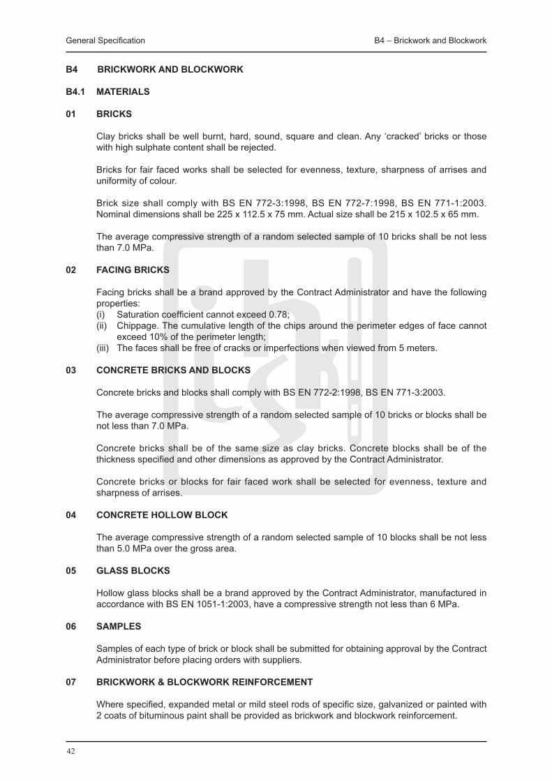
General Specification B4 – Brickwork and Blockwork
42
B4 BRICKWORK AND BLOCKWORK
B4.1 MATERIALS
01 BRICKS
Clay bricks shall be well burnt, hard, sound, square and clean. Any ‘cracked’ bricks or those with high sulphate content shall be rejected.
Bricks for fair faced works shall be selected for evenness, texture, sharpness of arrises and uniformity of colour.
Brick size shall comply with BS EN 772-3:1998, BS EN 772-7:1998, BS EN 771-1:2003. Nominal dimensions shall be 225 x 112.5 x 75 mm. Actual size shall be 215 x 102.5 x 65 mm.
The average compressive strength of a random selected sample of 10 bricks shall be not less than 7.0 MPa.
02 FACING BRICKS
Facing bricks shall be a brand approved by the Contract Administrator and have the following properties:
(i) Saturation coefficient cannot exceed 0.78; (ii) Chippage. The cumulative length of the chips around the perimeter edges of face cannot
exceed 10% of the perimeter length; (iii) The faces shall be free of cracks or imperfections when viewed from 5 meters.
03 CONCRETE BRICKS AND BLOCKS
Concrete bricks and blocks shall comply with BS EN 772-2:1998, BS EN 771-3:2003.
The average compressive strength of a random selected sample of 10 bricks or blocks shall be not less than 7.0 MPa.
Concrete bricks shall be of the same size as clay bricks. Concrete blocks shall be of the thickness specified and other dimensions as approved by the Contract Administrator.
Concrete bricks or blocks for fair faced work shall be selected for evenness, texture and sharpness of arrises.
04 CONCRETE HOLLOW BLOCK
The average compressive strength of a random selected sample of 10 blocks shall be not less than 5.0 MPa over the gross area.
05 GLASS BLOCKS
Hollow glass blocks shall be a brand approved by the Contract Administrator, manufactured in accordance with BS EN 1051-1:2003, have a compressive strength not less than 6 MPa.
06 SAMPLES
Samples of each type of brick or block shall be submitted for obtaining approval by the Contract Administrator before placing orders with suppliers.
07 BRICKWORK & BLOCKWORK REINFORCEMENT
Where specified, expanded metal or mild steel rods of specific size, galvanized or painted with 2 coats of bituminous paint shall be provided as brickwork and blockwork reinforcement.
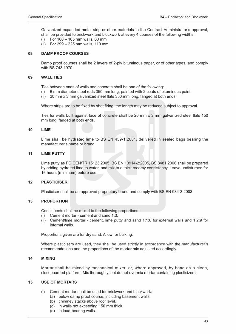
General Specification B4 – Brickwork and Blockwork
43
Galvanized expanded metal strip or other materials to the Contract Administrator’s approval, shall be provided to brickwork and blockwork at every 4 courses of the following widths:
(i) For 100 – 105 mm walls, 60 mm (ii) For 299 – 225 mm walls, 110 mm
08 DAMP PROOF COURSES
Damp proof courses shall be 2 layers of 2-ply bituminous paper, or of other types, and comply with BS 743:1970.
09 WALL TIES
Ties between ends of walls and concrete shall be one of the following: (i) 6 mm diameter steel rods 350 mm long, painted with 2 coats of bituminous paint. (ii) 20 mm x 3 mm galvanized steel flats 350 mm long, fanged at both ends.
Where strips are to be fixed by shot firing, the length may be reduced subject to approval. Ties for walls built against face of concrete shall be 20 mm x 3 mm galvanized steel flats 150
mm long, fanged at both ends.
10 LIME
Lime shall be hydrated lime to BS EN 459-1:2001, delivered in sealed bags bearing the manufacturer’s name or brand.
11 LIME PUTTY
Lime putty as PD CEN/TR 15123:2005, BS EN 13914-2:2005, BS 8481:2006 shall be prepared by adding hydrated lime to water, and mix to a thick creamy consistency. Leave undisturbed for 16 hours (minimum) before use.
12 PLASTICISER Plasticiser shall be an approved proprietary brand and comply with BS EN 934-3:2003.
13 PROPORTION
Constituents shall be mixed to the following proportions: (i) Cement mortar - cement and sand 1:3. (ii) Cement/lime mortar - cement, lime putty and sand 1:1:6 for external walls and 1:2:9 for
internal walls. Proportions given are for dry sand. Allow for bulking.
Where plasticisers are used, they shall be used strictly in accordance with the manufacturer’s recommendations and the proportions of the mortar mix adjusted accordingly.
14 MIXING
Mortar shall be mixed by mechanical mixer, or, where approved, by hand on a clean, closeboarded platform. Mix thoroughly, but do not overmix mortar containing plasticizers.
15 USE OF MORTARS (i) Cement mortar shall be used for brickwork and blockwork: (a) below damp proof course, including basement walls. (b) chimney stacks above roof level. (c) in walls not exceeding 150 mm thick. (d) in load-bearing walls.
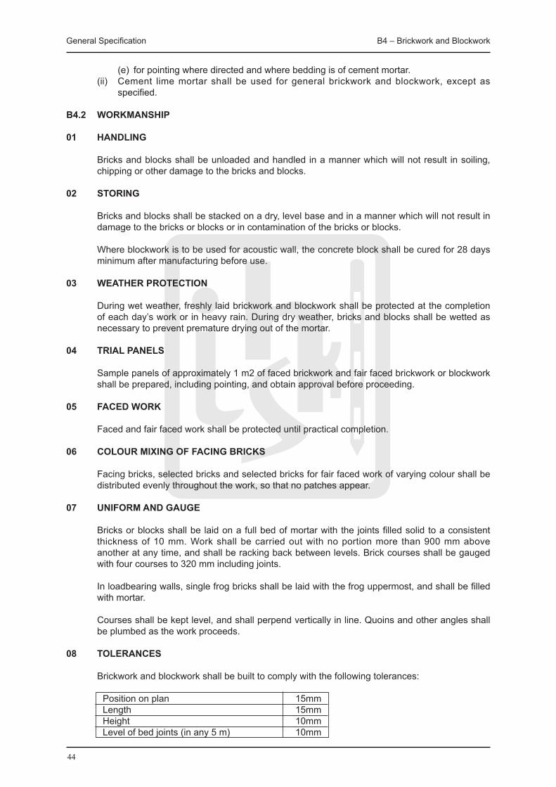
General Specification B4 – Brickwork and Blockwork
44
(e) for pointing where directed and where bedding is of cement mortar. (ii) Cement lime mortar shall be used for general brickwork and blockwork, except as
specified.
B4.2 WORKMANSHIP
01 HANDLING
Bricks and blocks shall be unloaded and handled in a manner which will not result in soiling, chipping or other damage to the bricks and blocks.
02 STORING
Bricks and blocks shall be stacked on a dry, level base and in a manner which will not result in damage to the bricks or blocks or in contamination of the bricks or blocks.
Where blockwork is to be used for acoustic wall, the concrete block shall be cured for 28 days minimum after manufacturing before use.
03 WEATHER PROTECTION
During wet weather, freshly laid brickwork and blockwork shall be protected at the completion of each day’s work or in heavy rain. During dry weather, bricks and blocks shall be wetted as necessary to prevent premature drying out of the mortar.
04 TRIAL PANELS
Sample panels of approximately 1 m2 of faced brickwork and fair faced brickwork or blockwork shall be prepared, including pointing, and obtain approval before proceeding.
05 FACED WORK
Faced and fair faced work shall be protected until practical completion.
06 COLOUR MIXING OF FACING BRICKS
Facing bricks, selected bricks and selected bricks for fair faced work of varying colour shall be distributed evenly throughout the work, so that no patches appear.
07 UNIFORM AND GAUGE
Bricks or blocks shall be laid on a full bed of mortar with the joints filled solid to a consistent thickness of 10 mm. Work shall be carried out with no portion more than 900 mm above another at any time, and shall be racking back between levels. Brick courses shall be gauged with four courses to 320 mm including joints.
In loadbearing walls, single frog bricks shall be laid with the frog uppermost, and shall be filled with mortar.
Courses shall be kept level, and shall perpend vertically in line. Quoins and other angles shall be plumbed as the work proceeds.
08 TOLERANCES
Brickwork and blockwork shall be built to comply with the following tolerances:
Position on plan 15mm Length 15mm Height 10mm Level of bed joints (in any 5 m) 10mm

General Specification B4 – Brickwork and Blockwork
45
Straightness (in any 5 m) 15mm Verticality (in any 3 m) 15mm
09 BONDING
70 mm and 105 mm brick walls shall be laid in stretcher bond. Brick walls 225 mm and over shall be laid in English bond, unless otherwise specified. Blockwork shall be laid in stretcher bond. Bricks throughout the work shall be laid with the perpends in any course not less than a quarter of a brick from those in the course below.
Notwithstanding the above, faced brick walls and fair faced brickwork or blockwork shall be laid with joints to an even and regular pattern.
10 TIES TO CONCRETE STRUCTURE
At junctions of walls with concrete structure, tie shall be cast in, cut and pin or shot fire to concrete at 320 mm centres vertically to project 250 mm into brick or block walls.
For brickwork or blockwork built against the face of concrete structure, ties shall be cast in or cut and pin to concrete at 900 mm centres horizontally, 300 mm centres vertically and staggered, to project 75 mm into brick or block walls.
11 FINISHING OF jOINTS
Joints which will not be visible in the finished brickwork and blockwork shall be struck off as the work proceeds.
Joints which will be exposed shall be struck flush and weather pointed as the work proceeds.
Joints in brickwork to which plaster or other wet applied finishes will be applied shall be raked out to a depth of 10 mm.
12 DAMP PROOF COURSE
Brickwork shall be flushed up to form a level and even bed with mortar used in the general brickwork to receive the horizontal damp proof course.
Damp proof course shall be laid in continuous strip with 150 mm laps at end of length and at returns, and mortar joint shall be completed to normal thickness.
13 WEDGING AND PINNING
Brickwork and blockwork to structural soffits shall be pinned up, wedged and filled solid with mortar.
14 BUILDING IN
Lintels shall be built in and solid door and window frames and the like shall be bedded with mortar similar to that of adjacent walls.
15 HOLES AND CHASES
Chases, holes, recesses and reveals shall be left, formed or cut in walls to receive frames, rainwater or other pipes, conduits, electric cables, sleeve and the like as required and subsequently be made good with mortar similar to that of adjacent walls.
16 GLASS BLOCK PANELS
All sides of structural opening to receive glass block panels shall be painted with two coats of bituminous paint.

General Specification B4 – Brickwork and Blockwork
46
Blocks shall be laid in cement/lime mortar and be pointed both sides. 12 mm clearance at jambs and head of panels shall be provided. Gap shall be filled with movement joint filler and be sealed both sides.
Strips of blockwork reinforcement 64 mm wide shall be built in at every fourth course. Ends of strips shall be carried across the clearance gap and be built into or secured to jambs of opening in an approved manner.
Proprietary fixing components supplied by glass block manufacturer shall be used, and all fixing details recommended by the manufacturer shall be followed unless required to do otherwise by the Contract Administrator.
B4.3 TESTING
01 COMPRESSIVE STRENGTH (i) Each brick or block in the sample shall be tested to determine the compressive strength of
the brick or block. (ii) The method of testing shall be in accordance with BS EN 772-3:1998, BS EN 772-7:1998,
BS EN 771-1:2003. (iii) The average of the 10 compressive strengths of the bricks or blocks shall be calculated
and referred to as the compressive strength.
B4.4 REPAIRING
01 REPAIR OF CRACKED BLOCKWORK AND BRICKWORK WALLS (CEMENT/SAND)
Cracks to walls shall be raked out to a depth of 25mm from the surface of the brick/block surface as directed by the Contract Administrator.
The crack shall be washed with a cement / slurry to provide a key. New 1:4 cement sand mortar shall be applied and pressed well into crack so as to ensure the crack is well filled. Mortar level shall be brought with the surface of the brickwork/blockwork and shall be left ready to receive decoration.
02 REPAIR OF CRACKED BLOCKWORK AND BRICKWORK WALLS (INjECTION)
Crack repair system to brick and block walls shall be proprietary product as approved by the Contract Administrator.
All loose plaster, render, paint finish shall be removed and crack shall be thoroughly cleaned with the use of approved proprietary cleaner, and shall be left ready to receive injection resin grout.
Surface and flanges of crack shall be sealed with approved proprietary epoxy gel in full accordance with the manufacturers recommendations and instructions. Holes shall be drilled at 150mm consecutive centres and plastic injection ports shall be inserted as requires.
Holes shall be injected with approved resin grout fully in accordance with the manufacturers recommendations and instructions, commencing at the bottom of the crack and working upwards. The crack top and bottom shall be injected in turn until each lift of the crack is full.
Excessive epoxy resin gel shall be removed and the surface shall be left ready to receive plaster and decoration as specified elsewhere.

47
PlasteringandRendering
B5

General Specification B5 – Plastering and Rendering
48
B5 PLASTERING AND RENDERING
B5.1 MATERIALS
01 CEMENT, WATER AND SAND
Cement for plasterwork and other finishes shall be Ordinary Portland Cement complying with BS EN 197-1.
Water for plasterwork and other finishes shall be clean fresh water taken from the public supply.
Sand for mixes for plasterwork and other finishes which do not incorporate lime shall be clean, hard, durable crushed rock or clean sand and shall have the particle size distribution stated in Table B5.1.1. Sand for mixes which incorporate lime shall be clean natural sand and shall have the particle size distribution stated in Table B5.1.2. The quantity of clay, fine silt and fine dust present in the sand shall not exceed 10% by mass when determined in accordance with BS 812: Part 101, BS 812: Part 102, BS 812: Part 103 and BS 812: Section 105.1. The chloride content of sand or crushed rock shall not exceed 0.03% by mass when determined in accordance with BS 812: Part 4.
Table B5.1.1: Particle size distribution of sand for mixes which do not incorporate lime
BS test sieve size Percentage by mass passing 5.00 mm 100 2.36 mm 90 – 100 1.18 mm 70 – 100 600 μm 40 – 80 300 μm 5 – 40 150 μm 0 – 10
Table B5.1.2: Particle size distribution of sand for mixes incorporating lime
BS test sieve size Percentage by mass passing 2.36 mm 100 1.18 mm 90 - 100 600 μm 55 - 100 300 μm 5 - 50 150 μm 0 - 10
02 GYPSUM PLASTERS
Gypsum plaster shall be retarded hemihydrate gypsum plaster to BS 1191:Pt. 1, Class B of the following types:
Undercoat Plaster Type a - 1 Browning plaster 2 Metal lathing plaster Final Coat Plaster Type b - 1 Finish plaster 2 Board finish plaster 03 PREMIXED PLASTER
Premixed plaster shall be factory-produced by weighted combination of plaster raw materials and chemicals. It shall be supplied to sites in bags. Mixing with clean water shall be required before application.
The premixed plaster shall comply with BS 5262, BS 5492 and BS 1191. The premixed plaster manufacturing company shall have acquired ISO certification in their manufacturing process of the premixed plaster product.

General Specification B5 – Plastering and Rendering
49
04 LIME
Lime for plastering shall be hydrated lime or quicklime complying with BS 890.
05 SPATTERDASH
Spatterdash shall consist of cement and coarse sand or granite fines in the proportion 1:2 by volume mixed with the minimum amount of water necessary to achieve the consistency of a thick slurry.
06 STEEL LATHING
Steel lathing shall comply with BS 1369:Part 1 from an approved manufacturer: (i) Plain expanded type of 6 mm short way mesh coated with tight coat galvanizing and
weighing not less than 1.6 kg/m2
(ii) Ribbed expanded type similarly coated and weighing not less than 2.25 kg/m2.
07 METAL BEADS AND PLASTIC BEADS Metal beads for internal plastering and dry lining shall be to BS 6452:Pt. 1.
Galvanized steel corner beads, plaster stops and movement joint beads shall have expanded metal wings and be supplied from an approved manufacturer.
Plastic corner beads shall be used if approved by the Contract Administrator.
08 WIRE NETTING
Wire netting shall comply with BS 1485, and made of 0.9 mm galvanized wire and 50 mm mesh.
09 STAPLES
Staples shall be galvanized steel wire staples.
10 TYING WIRE
Tying wire shall be 1.25 mm annealed steel wire, galvanized to BS 443.
11 PLASTERBOARD
Plasterboard shall comply with BS 1230:Pt. 1, "gypsum lath" or "gypsum baseboard" with square edges.
12 NAILS FOR PLASTERBOARD
Nails for “lath” or “baseboard” shall be 30 x 2.6 mm plasterboard galvanized steel nails, jagged shank type to BS 1202:Pt. 1.
(i) 30 x 2.65 mm for plasterboard not exceeding 12.7 mm thick (ii) 40 x 2.65 mm for plasterboard 19 mm thick
13 jOINT REINFORCEMENT
Reinforcement for joints in plasterboard shall be jute scrim cloth not less than 90 mm wide.
14 HANDLING AND STORAGE OF PLASTERBOARD
Plasterboard shall be carried on edge. Plasterboard shall be stacked flat on level surface, properly supported to prevent sagging or bending of boards off the ground and inside a building. Plasterboard shall be kept dry to prevent mould growth, and deliveries shall be

General Specification B5 – Plastering and Rendering
50
programmed to ensure that storage periods on site are kept to a minimum during periods of high humidity.
15 ACOUSTIC PLASTER
Acoustic plaster shall be an approved proprietary brand free from asbestos, mixed and applied in accordance with manufacturer’s recommendations.
16 STONE CHIPPINGS
Stone chippings for exposed aggregate rendering or Shanghai plaster shall be granite, white stone or marble chippings, graded from 3 to 5 mm, and free from dust.
17 HIGH qUALITY FINISHES
Resin, epoxy, urethane and acrylic based decorative finishes shall be approved proprietary products applied by approved specialist contractors.
18 BONDING AGENT
Bonding agent shall be compatible with background and finish, designated to be suitable for internal or external use and shall be an approved proprietary brand.
The approved proprietary bonding agent shall be used in strict accordance with the manufacturer’s technical specifications and recommendations, including and not limited to the valid shelf life of the product. The expiry date shall be clearly indicated with label and stamp for necessary inspection by the Contract Administrator.
B5.2 WORKMANSHIP
01 GENERAL
Plastering and rendering shall generally be in accordance with BS 5492 and BS 5262 respectively.
02 BACKGROUND PREPARATION FOR PLASTERING AND RENDERING
Background for plastering and rendering shall comply with BS 5385:1995 and BS 8000:1989.
03 APPLYING SPATTERDASH TO NEW CONCRETE
New concrete surfaces which are to be plastered or rendered shall be spatterdashed immediately after the formwork has been removed or shall be treated with a proprietary type of bonding agent approved by the Contract Administrator.
Spatterdash shall be thrown with a hand trowel onto the surface to a thickness not exceeding 6 mm and shall cover at least 60% of the area that is to be plastered or rendered. Spatterdash shall be wetted one hour after application and shall be allowed to cure and harden for at least two days before undercoats are applied.
After hardening and curing, the adhesion of the spatterdash coat shall be checked by brushing with a stiff wire brush. Where spatterdash is easily removed, loosened spatterdash shall be completely removed. Spatterdash shall be re-applied and re-inspected after 7 days.
04 PREPARATION OF HARDENED CONCRETE TO RENDERS
Existing concrete surfaces shall be hacked uniformly over the complete area to expose the aggregate over at least 50% of the area.
High pressure water jet shall be used to remove efflorescence, laitance, oil, formwork release

General Specification B5 – Plastering and Rendering
51
agent, grease, dirt and loose materials from the concrete surfaces before application of subsequent finishes.
Concrete surface shall be prepared by bushing neat cement slurry into the damp surface immediately before applying the finish or by applying bonding agent in accordance with the manufacturer’s recommendations.
05 DUBBING OUT
When it is necessary to correct inaccuracies in the background, dubbing out shall be in layers of a maximum thickness of 10 mm in the same mix as the first coat and to a total thickness not exceeding 25 mm.
Each coat shall be cross scratched to provide a key for the next and be allowed to dry out before applying the next.
06 FIXING STEEL LATHING
The largest dimension of the mesh shall be perpendicular to the direction of the supports. The lathing shall extend at least 150 mm along each side of the junction and shall be fixed at 100 mm centres with galvanized steel staples, nails or tying wire as appropriate to the nature of the background.
The galvanized steel staples and nails shall comply with BS EN ISO 1461: 1999 while the tying wire shall be in accordance with BS EN 10244-2: 2001 or otherwise approved by the Contract Administrator.
Laps shall be at least 50 mm where end laps occur between supports and shall be at least 25 mm at other locations. Laps shall be secured with tying wire at 75 mm centres.
Cut ends of lathing shall be painted with one coat of bituminous paint.
Exposed external arrises of plastering or rendering shall be formed at right angles made with galvanized steel corner beads, which shall comply with BS EN ISO 1461: 1999 or otherwise approved by the Contract Administrator.
Junctions between dissimilar solid backgrounds in the same plane that are to be plastered or rendered shall be jointed with a strip of metal lathing.
Base coats and first coats of plastering and rendering shall be cross scratched to provide a key for the next coat.
07 MIXING PLASTER AND RENDER
Mixing plaster and render shall be in accordance with BS 8000: Part 10: 1989. Unless otherwise permitted by the Contract Administrator, the materials shall be mixed by mechanical methods.
Plaster and render shall be mixed using minimum amount of water necessary to achieve required consistency making due allowance for the moisture content of sand and shall be used within one hour after mixing. Too strong or too wet render mix that increase the render drying shrinkage shall be avoided.
The mixed materials shall not be reconstituted and shall not be used after the initial set has taken place. Renders containing plasticizers shall not be over-mixed and the constituents shall be dried before mixing with lime putty or water. Admixtures should not be used for mixing gypsum plaster.
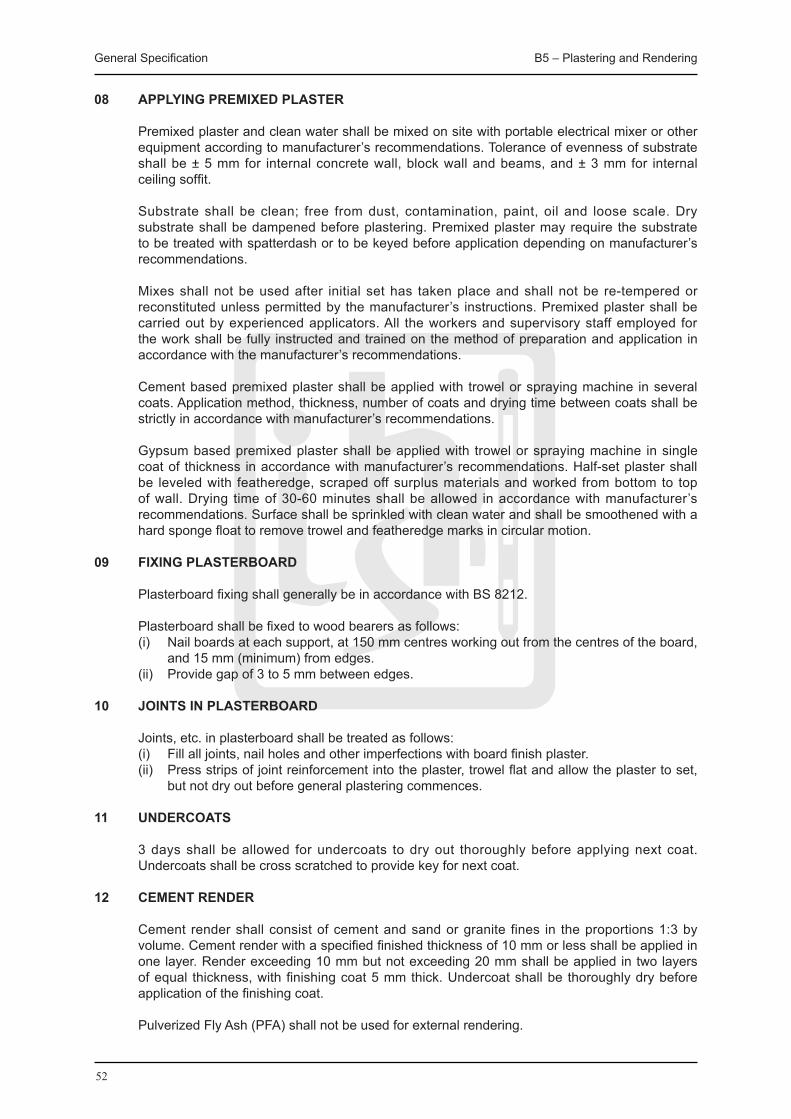
General Specification B5 – Plastering and Rendering
52
08 APPLYING PREMIXED PLASTER
Premixed plaster and clean water shall be mixed on site with portable electrical mixer or other equipment according to manufacturer’s recommendations. Tolerance of evenness of substrate shall be ± 5 mm for internal concrete wall, block wall and beams, and ± 3 mm for internal ceiling soffit.
Substrate shall be clean; free from dust, contamination, paint, oil and loose scale. Dry substrate shall be dampened before plastering. Premixed plaster may require the substrate to be treated with spatterdash or to be keyed before application depending on manufacturer’s recommendations.
Mixes shall not be used after initial set has taken place and shall not be re-tempered or reconstituted unless permitted by the manufacturer’s instructions. Premixed plaster shall be carried out by experienced applicators. All the workers and supervisory staff employed for the work shall be fully instructed and trained on the method of preparation and application in accordance with the manufacturer’s recommendations.
Cement based premixed plaster shall be applied with trowel or spraying machine in several coats. Application method, thickness, number of coats and drying time between coats shall be strictly in accordance with manufacturer’s recommendations.
Gypsum based premixed plaster shall be applied with trowel or spraying machine in single coat of thickness in accordance with manufacturer’s recommendations. Half-set plaster shall be leveled with featheredge, scraped off surplus materials and worked from bottom to top of wall. Drying time of 30-60 minutes shall be allowed in accordance with manufacturer’s recommendations. Surface shall be sprinkled with clean water and shall be smoothened with a hard sponge float to remove trowel and featheredge marks in circular motion.
09 FIXING PLASTERBOARD
Plasterboard fixing shall generally be in accordance with BS 8212.
Plasterboard shall be fixed to wood bearers as follows: (i) Nail boards at each support, at 150 mm centres working out from the centres of the board,
and 15 mm (minimum) from edges. (ii) Provide gap of 3 to 5 mm between edges.
10 jOINTS IN PLASTERBOARD
Joints, etc. in plasterboard shall be treated as follows: (i) Fill all joints, nail holes and other imperfections with board finish plaster. (ii) Press strips of joint reinforcement into the plaster, trowel flat and allow the plaster to set,
but not dry out before general plastering commences.
11 UNDERCOATS
3 days shall be allowed for undercoats to dry out thoroughly before applying next coat. Undercoats shall be cross scratched to provide key for next coat.
12 CEMENT RENDER
Cement render shall consist of cement and sand or granite fines in the proportions 1:3 by volume. Cement render with a specified finished thickness of 10 mm or less shall be applied in one layer. Render exceeding 10 mm but not exceeding 20 mm shall be applied in two layers of equal thickness, with finishing coat 5 mm thick. Undercoat shall be thoroughly dry before application of the finishing coat.
Pulverized Fly Ash (PFA) shall not be used for external rendering.

General Specification B5 – Plastering and Rendering
53
13 INTERNAL LIME PLASTER
Lime plaster for internal use shall be applied in two coats on solid backgrounds. The first coat shall consist of cement and sand in the proportion 1:3 by volume and shall not exceed 10 mm thick on walls and 5 mm thick on soffits. The second coat shall consist of cement, lime and sand in the proportions 1:2:6 by volume and shall be 5 mm thick. Metal plaster corner beads and stops shall be provided. The total thickness shall not exceed 15 mm on walls and 10 mm on soffits.
Lime plaster for internal use shall be applied in three coats on metal lathing. The first coat and the second coat shall consist of cement and sand in the proportion 1:3 by volume. The finishing coat shall consist of cement, lime and sand in the proportion 1:2:6 by volume and shall be 5 mm thick. The total thickness shall not exceed 13 mm measured from the outer face of the metal lathing.
Pulverized Fly Ash (PFA) shall not be used for internal plastering.
14 GYPSUM PLASTER
Gypsum plaster shall be applied in two coats on solid backgrounds. The first coat shall consist of Browning plaster and sand in the proportion 1:2 by volume and the finishing coat shall consist of neat finish plaster to give a total thickness not exceeding 15 mm.
Gypsum plaster shall be applied in three coats on metal lathing. The first coat shall consist of metal lathing plaster and sand in the proportion 1:1½ by volume. The second coat and the finishing coat shall be as stated in Clause B5.2 110 for the first coat and the finishing coat respectively. Total thickness of plaster shall not exceed 13 mm measured from the outer face of the metal lathing.
If approved by the Contract Administrator, proprietary gypsum plaster can be used in strict accordance with the manufacturer’s technical specifications and recommendations.
Where specified, bonding agents for use with gypsum plaster shall be as BS 5270:Pt. 1.
15 GYPSUM PLASTER ON PLASTERBOARD
Gypsum plaster shall be applied as one finishing coat 5 mm (maximum) thick on plasterboard trowelled to a smooth surface using as little water as possible.
16 ARRISES
Arrises shall be square or pencil rounded, as required.
17 METAL BEADS
Metal corner beads, plaster stops and movement joints shall be provided and fixed when specified including nailing, stapling or fixing with plaster dabs and trowel the finishing coat flush with the bead.
18 CORNICES
Coved or moulded cornices shall be either: (i) Formed with a backing of cement and sand 1:3 with finishing coat of same plaster used
for adjacent surfaces, finished with a steel template to a smooth finish. (ii) Preformed cornices from an approved manufacturer fixed in accordance with
manufacturer’s recommendations.
19 EXPOSED AGGREGATE RENDERING OR “SHANGHAI” PLASTER
Exposed aggregate rendering or “Shanghai” plaster shall be applied in two coats, each 10 mm thick.
General Specification B5 – Plastering and Rendering
54
The base coat shall consist of cement and sand in the proportion 1:3 by volume. The finishing coat shall consist of cement and stone chippings or marble chippings in the proportions 1:1 by volume.
After the finishing coat has set, the surface shall be scrubbed off to expose the aggregate.
20 SURFACE FINISHES
Surface finishes shall be either: (i) Smooth finish: finish with a steel trowel or power float to a smooth surface, free from
blemishes. (ii) Wood float finish: finish with a dry wood float to give an even overall surface. (iii) Textured finish: finish by stippling, scraping or other means to produce an approved
textured surface. (iv) Rough cast finish: throw onto the undercoat a wet mix of aggregate and cementitious
materials. (v) Machine applied textured finish: apply in accordance with the manufacturer ’s
recommendations.
21 MOVEMENT jOINTS
Movement joints shall be constructed at a maximum 4m centres in each direction equally spaced or as directed by the Contract Administrator to accord with dimensioned requirements.
22 PROTECTION
All finishes shall be protected from discolouration or damage until completion. Completed and partially completed surfaces of plasterwork and other finishes shall be protected from rapid or localised drying out for at least 7 days by covering with polythene sheeting, or by other methods agreed by the Contract Administrator.
B5.3 REPAIRING
01 REPAIR TO SKIRTING / DADO
Defective skirting / dado shall be hacked off after saw-cut around the defective area. Before applying new finishes, surface shall be prepared by scabbling and cleaning. Finishes shall be applied to match existing skirting / dado in every respect.
02 REPAIR TO DEBONDED AND BULGED WALL PLASTER / RENDER
All debonded and bulged plaster / render shall be hacked off after saw-cut around the perimeter of the areas to be repaired perpendicular to the surfaces and for the full depth of the plaster / render. Cut lines shall produce a rectangular area for repair.
Defective area shall be repaired with matching finishes subject to the Contract Administrator approval.
03 REMOVAL OF FLOOR FINISHES
Where floor finishes are to be removed, it shall be broken up and cleared away from site. At the junction of all work joints, and joints with existing floor finishes, neat joints shall be provided by using a stone cutting devise to form a chase of 3mm minimum width and run the full depth of the screed. The depth of the screed shall first be established before setting the gauge of the saw cutter to the appropriate depth. The saw shall not cut through to the concrete slab. Substrate shall be clean and be removed from all deleterious materials. The base and upstand surfaces shall be clean, dry, and even, and are ready to receive new floor screed and floor tiling.

55
TilingandCladding
B6
General Specification B6 – Tiling and Cladding
56
B6 TILING AND CLADDING
B6.1 MATERIALS
01 TILES The contractor shall refer to the Particular Specifications and Drawings of the type of tiles
issued for the Contract. All tiles specified shall include full range of all necessary special tiles: coved, corner, edge tiles and all accessories tiles for a complete installation.
Each type of tile and fitting shall be obtained from the same manufacturer and shall match in colour and texture.
Sample of specified tiles shall be submitted to the Contract Administrator for approval before material is ordered.
02 CERAMIC WALL TILES
All tiles and tile fitting shall comply with the following BS EN 14411:2006:- (i) All tiles shall be true and even on face and of even thickness throughout. Unless otherwise
specified, the thickness for the floor tiles shall be 7mm min. (ii) All tiles shall have cushion edges and the ability of being cut and mitred. (iii) The backs of the tiles shall be formed with a bond undercut key sufficient to ensure a good
grip of the fixing medium. The projection of key shall be 0.6mm min. (iv) Permissible maximum deviations for the tiles shall be as follows: (a) Tile facial size: the range of deviations in the size I individual consignment shall not
exceed 0.5%. (b) Thickness: variation of individual size from the average value for the batch shall not
exceed 0.3mm. (c) Tile fitting: the range of deviations in the sizes.
03 MOSAIC TILES
Glass mosaic tiles shall be fully vitrified glass tiles free from cracks or sharp edges and shall be uniform in colour and texture. The tiles shall be 20 mm x 20 mm x 4 mm thick and shall be regular in shape.
Glazed ceramic mosaic tiles shall be free from cracks or sharp edges and shall be uniform in colour and texture. The tiles shall be 18 mm x 18 mm x 5 mm thick or 25 mm x 25 mm x 5 mm thick and shall be regular in shape with square edges.
Unglazed vitreous mosaic tiles shall have a water absorption not exceeding 3% and shall be 20 mm x 20 mm or 50 mm x 50 mm and shall be respectively 4 mm or 5 mm thick with matching coved tiles.
04 HOMOGENOUS COVED TILE SKIRTING
Homogenous coved tile skirting shall comply with BS EN ISO 10545-2:1997, BS EN ISO 10545-3:1997, BS EN ISO 10545-6:1997, BS EN ISO 10545-8:1996, BS EN ISO 10545-13:1997.
05 HOMOGENOUS WALL TILES Homogenous wall tiles shall comply with BS EN ISO 10545-2:1997, BS EN ISO 10545-3:1997,
BS EN ISO 10545-4:1997, BS EN ISO 10545-6:1997, BS EN ISO 10545-8:1996 and BS EN ISO 10545-13:1997.
06 EXTERNAL FACING TILES
External facing tiles shall be of the specified type from an approved manufacturer and comply
General Specification B6 – Tiling and Cladding
57
with BS EN ISO 10545-2:1997, BS EN ISO 10545-3:1997, BS EN ISO 10545-4:1997, BS EN ISO 10545-8:1996, BS EN ISO 10545-11:1996, BS EN ISO 10545-14:1997, BS EN ISO 10545-13:1997 and BS EN ISO 10545-7:1999.
07 TILE ADHESIVE AND TILE GROUT
Tile adhesive shall be of a proprietary brand approved by the Contract Administrator. Tile adhesive and tile grout shall be cement-based and be compatible with the substrate and tiles to be installed.
Tile adhesive shall be in accordance with BS EN 12004:2007 cementitious adhesive, normal setting type with minimum tensile adhesion strength of 0.5N/mm², and comply with Table B 6.1.1.
Table B 6.1.1. Tensile adhesion strength
Characteristic Requirement Test Method Initial tensile adhesion strength ≥ 0.5 N/mm² 8.2 of BS EN 1348:2007 Tensile adhesion strength after ≥ 0.5 N/mm² 8.3 of BS EN 1348:2007 water immersion Tensile adhesion strength after ≥ 0.5 N/mm² 8.4 of BS EN 1348:2007 heat ageing Tensile adhesion strength after ≥ 0.5 N/mm² 8.5 of BS EN 1348:2007 freeze-thaw cycles Open time: tensile adhesion ≥ 0.5 N/mm² BS EN 1346:2007 strength after not less than 20 min
Tile grout shall be in accordance with ANSI A118.6: 1992, and comply with Table B 6.1.2.
Table B 6.1.2: Tile grout test acceptance standards
Items Test Method Acceptance Remarks Standards Linear ANSI A118.6: 1992 1 day shrinkage Cast and store grout Shrinkage Clause H4.3 < 0.1% specimens at 21° - 25°C, 45 7 days shrinkage - 55% R.H. < 0.2% Water ANSI A118.6: 1992 From 50% R.H. to Determine water absorption Absorption Clause H3.4 immersion < 5% from From immersion to 50% R.H. to immersion and dry < 7% from immersion to dry. Compatibility BS EN 12004:2007 Requirements of with Tile Appendix D with BS 5980: 1980 are Adhesive modification. taken > = 950N for 14 days in laboratory condition > = 560N for 7 days curing in laboratory condition followed by 7 days immersion in water (Tensile A layer of tile Adhesion) grout is applied on Laboratory tile adhesive for Condition: tensile adhesion 20° ± 2°C test 45 to 75% R.H.
A layer of tile grout (1.5 mm thick) is applied over t i le adhesive 1.5 mm thick (brand to be the one selected by the Contract Administrator) which shall have been embedded in standard test piece tiles to harden fo r 24 hours . Ten such assemblies are prepared and cured for 14 days at laboratory condition and then subject to tensile force. Further ten assemblies are required for similar tensile tests under 7 days curing at laboratory condition followed by 7 days immersion in water.
General Specification B6 – Tiling and Cladding
58
Resistance to BS EN 12004:2007 No sign or evidence Mould Appendix B of mould growth on Growth tile grout.
The colour of the tile adhesive shall be white or grey and the colour of the grout shall be subject to the approval of the Contract Administrator.
Tile adhesive and tile grout shall be packed in three ply together with preparation procedures and application methods. Minimum one set of the preparation procedures and application methods shall be printed in Chinese and diagrammatic forms for each lot that is delivered to site. Brand name, batch number, shelf life, pot life and open time shall be clearly printed on the outside of package.
08 WARPAGE
Tiles: it shall not exceed 0.5mm for any tiles in one batch.
Tile Fittings: it shall not exceed 0.5mm for any tile in one batch.
09 CURVATURE
Tiles: it shall not exceed a concavity of 0.13mm or convexity of 0.76 mm of any tile in one batch.
10 WATER ABSORPTION GROUP
(i) Tiles of low water absorption (Group I) E < 3% (ii) Tiles of medium water absorption (Group II) 3% < E < 10% Group II is further divided as follows: 3% < E < 6% (Group IIa) 6% < E < 10% (Group IIb) Tiles of high water absorption (Group III) E > 10% Note: Ceramic tiles are divided into groups according to their method of manufacture
and their water absorption (see Table). The groups do not presuppose the usage of the products.
(iii) Classification of ceramic tiles according to their groups and their specific product standard as below.
Water Absorption Group I Group IIa Group IIb Group III / Shaping E < 3% 3% < E < 6% 6% < E < 10% E > 10%
A (extruded tiles) Group AI Group AIIb Group AII Group AIII BS EN BS EN BS EN BS EN 14411:2003 14411:2003 14411:2003 14411:2003 B (dust pressed Group BI Group BIIa Group BII Group BIII tiles) BS EN BS EN BS EN BS EN 14411:2003 14411:2003 14411:2003 14411:2003 C (cast tiles) Group CI Group CIIa Group CIIb Group CIII
3 mm th ick t i le grout is appl ied over biscuit side of test piece t i le and the assembly be placed in Petri dishes for incubation at 29° ± 1°C for 24 hrs after addition of potato dextrose agar. Aspergillus niger is inoculated into the grout. The whole assemble is incubated for 14 days at 29° ± 1°C.
General Specification B6 – Tiling and Cladding
59
11 A BRIEF SPECIFICATION Specification of tiles shall be submitted which shall include the following:- (i) The description of the tiles, e.g. split, dust pressed etc.; (ii) The number of the relevant standard, e.g. BS EN 14411:2003; (iii) The classification as given in this standard (See Table); (iv) The nominal size and the work size, thickness, max. tolerance; (v) The nature of the tile surface: whether glazed or unglazed; (vi) Physical properties and chemical resistance in accordance with relevant test standards e.g.
water absorption, scratch hardness, crazing resistance of glazed tiles, resistance to deep abrasion to thermal shock etc.
12 SAMPLES
Samples shall be properly mounted on a sample board which shall be black in colour. The samples must be clearly marked with the origin, size, colour, and brand number and shall be representative of quality of the offer.
3 sets of samples shall be submitted for approval before delivery in bulk is made and subsequent goods delivered to the site shall be equal to the approved sample.
All samples submitted shall be undamaged and in good condition.
B6.2 WORKMANSHIP
01 WALL TILING
Internal wall tiling shall comply with BS 5385:Pt.1:2009, external wall tiling shall comply with BS 5385:Pt. 2:2006.
02 EXISTING BACKGROUNDS / BASES
Efflorescence, laitance, dirt and other loose materials shall be thoroughly removed by dry brushing.
Substances incompatible with the bedding shall be removed by using suitable emulsion cleaner
then washed with clean water. All loose or defective areas shall be removed and repaired with materials compatible with the
background/base and bedding. Plaster primer shall be applied if recommended by the adhesive manufacturer and it shall be
allowed to dry before tiling.
03 FIXING Unintended colour/shade variations shall be avoided within the tiles for use in each area/room.
Variegated tiles shall be thoroughly mixed. Adhesive shall be checked for compatibility with the background/base. Cut tiles neatly and accurately. Unless specified otherwise, tiles shall be fixed so that there is adhesion over the whole of the
background/base and tile backs. Before bedding material sets, necessary adjustments shall be made to give true, regular
appearance to tiles and joints. Variations in gap under a 2 m straightedge (with feet) placed anywhere on the surface shall not

General Specification B6 – Tiling and Cladding
60
be more than 3 mm. Surplus bedding material from joints and face of tiles shall be cleaned.
04 SETTING OUT Joints shall be true to line, continuous and without steps. Joints on walls shall be truly horizontal, vertical and in alignment round corners. Cut tiles shall be kept to the minimum, as large as possible and in unobtrusive locations. 05 FIXING WALL TILES
Tiles shall be fixed to wall render as follows:
(i) Thick bed method: (a) Sort and remove tiles with uneven colour or dimensions. Soak tiles in clean water
for 30 minutes (minimum). Stack to drain and fix as soon as the surface water has drained off.
(b) Damp the wall render with clean water sufficiently to prevent it absorbing water from the bedding mortar.
(c) Butter the back of each tile with cement slurry and tap firmly into position so that the bed is solid throughout. Thickness of finished bed shall be 5 to 15 mm.
(d) Joints shall be 2 mm (minimum) wide, and maximum 3.5 mm wide unless specified otherwise.
(e) Make any adjustment to tiles within 10 minutes of fixing. (f) Clean tiles and joints before bedding hardens. (g) Grout up joints 24 hours (minimum) after fixing tiles. Clean off surplus grout as work
proceeds. (h) Clean tiles at completion.
Thick bed method shall not be used for fixing wall tiles with water absorption value lower than 0.5%.
(ii) Thin bed method: (a) Apply wall render of cement:sand (1:3) to the concrete or substrate surface. Build up
the render to the required thickness of 15 mm in layers. Thickness of each layer shall not exceed 10 mm. Allow the wall render to dry off thoroughly.
(b) Fix wall tiles, mixed from six boxes, to the wall render using an approved proprietary adhesive to BS EN 12004:2007 in accordance with the manufacturer’s recommendations.
(c) Grout up joints using an approved grout or a proprietary grout to BS EN 13888:2009.
06 FIXING EXTERNAL WALL TILES
External wall tiles shall be fixed by thin bed method as follows:
(i) Apply wall render of cement:sand (1:3) to the substrate surface. Build up the render to the required thickness of 15 mm in layers. Thickness of each layer shall not exceed 10 mm. Allow the wall render to dry off thoroughly.
(ii) Fix wall tiles, mixed from six boxes, to the wall render using an approved proprietary adhesive to BS EN 12004:2007 in accordance with the manufacturer’s recommendations. Width of joints shall be as specified.
(iii) Grout up joints using an approved grout or a proprietary grout to BS EN 13888:2007.
Upon completion of the tiling works, appropriate test methods, such as in-situ pull-out tests by specialist contractor and hammer tapping, shall be carried out to ensure that the external facing tiles have been applied properly to achieve the required adhesion to the building structure or substrate surface according to the approved proprietary tile adhesive.

General Specification B6 – Tiling and Cladding
61
Infra-red thermographic scanning shall be carried out by an approved specialist and the report shall be submitted within 4 months upon completion of external tiling. Should the report indicate that any part of the wall tiling has not been affixed properly, the Contractor shall carry out approved remedial measures at his own expense and carry out further infra-red thermographic scanning to the satisfaction of the Contract Administrator.
07 FIXING MOSAIC TILES
Mosaic tiles shall be fixed as follows:
(i) Thick bed method direct to concrete slab as follows: (a) Lay semi-dry mix cement and sand 1:4 bed thoroughly compacted to the required
thickness (20 mm minimum) finished to the required levels and falls. (b) Pour cement and sand slurry over the bedding and spread and trowel 3 mm thick. (c) Coat back of sheets of mosaic tiles with cement slurry immediately before fixing.
Slurry shall be of the same colour as the final grout. (d) Fix sheets of mosaic tiles and tamp firmly into the bed, maintaining straight and
regular joints, and ensuring that joints between sheets are equal to tile joints. (e) Remove backing paper, complete final straightening and rub surface with grout,
coloured as required, to fill joints, cleaning surplus grout from face of tiles as work proceeds.
(ii) Thick bed method to wall render as follows: (a) Damp the wall render with clean water sufficiently to prevent it absorbing water from
the bedding mortar. (b) Apply bedding coat of mortar 10 mm (maximum) thick consisting of cement and sand
(1:3). (c) Coat surface of wall render and back of sheets of mosaic tiles with slurry immediately
before fixing. Slurry shall be of the same colour as the final grout. (d) Fix sheets of mosaic tiles and tamp firmly into position, maintaining straight and
regular joint, ensuring that joints between sheets are equal to joints between tiles. (e) Remove backing paper, complete final straightening and rub surface with grout from
face of tiles as work proceeds. (iii) Thin bed method: (a) If approved, fix mosaic tiles using a bed of proprietary adhesive in accordance with the
manufacturer’s recommendations. (b) Grout up joints using a proprietary grout as specified, which may be coloured in
accordance with Contract Administrator requirements.
08 TILE BONDING
(i) Thoroughly dampen the render surface with water and allow excess to drain away. (ii) Apply Tile Set Mortar while the surface is still damp and spread with a notched trowel. (iii) Limit application to an area that can be covered in tiles within 20-30 minutes. (iv) Set tiles onto the moist mortar and tap firmly into place. (v) Clean excess mortar from the tiles before the Tile Set has hardened. (vi) Do not apply mortar at temperatures below 0oC and above 35oC.
09 RIBBED ADHESIVE BEDDING TO WALLS Adhesive shall be applied in 3 mm floated coat and trowelled to a ribbed profile using the
recommended notched trowel. Tiles shall be pressed firmly into adhesive with a twisting sliding action.
10 SOLID ADHESIVE BEDDING TO WALLS Adhesive shall be applied in floated coat and surface shall be combed with the recommended
solid bed trowel. Dry tiles shall be applied with thin even coat of adhesive and pressed onto bedding with twisting/sliding action to eliminate voids. Bed thickness shall be within the range recommended by the manufacturer.

General Specification B6 – Tiling and Cladding
62
11 COLOUR GROUTING OF TILE jOINTS
Preparations:- (i) Ensure that tile adhesive has dried before grouting – 24 hours minimum, depending upon
application. (ii) Remove all adhesive, oil, dust and other loose materials from within the joints. (iii) When grouting out of direct sunlight and in temperatures below 27oC – ensure that joints
are dry. (iv) When grouting vertical surfaces in temperatures above 32oC and the tiles are warm to
the touch – brush splash the tiles and joints prior to commencing grouting, allowing the surface water to evaporate.
(v) When grouting floor tiles in direct sunlight and in temperatures above 22oC and the tiles are warm to the touch - brush splash the tiles and joints prior to commencing grouting, allowing the surface water to evaporate.
Applications:- (i) Apply the grout with a rubber squeegee or trowel. Work it into the joints with a diagonal or
circular motion to ensure that the joints are completely filled with grout. (ii) Clean excess grout from the surface of the tile as the work proceeds. (iii) When the film of grout on the tile is drying, it is time to wipe off with a damped but not wet
rubber sponge. For a perfect job a gloved finger should be run along the joints to ensure a perfectly smooth even joint.
Cleaning up:- (i) Clean tools and equipment immediately in water. Polish tiles surface with a soft cloth
approximately 6 hours after grouting. (ii) Allow 24 hours before putting tiled areas into service.
12 MOVEMENT / EXPANSION jOINT
All mortar shall be thoroughly raked from joints so that the joints are entirely open from the surface of the tiles.
The joints shall be filled with a form plastic or filler, stripped to a depth of 12mm or the width of the joint below the surface of the tiles, and neatly pointed flush with sealant of approved type and colour.
The whole sealant installation work shall be supplied and installed complete at the main contractor’s expense by the manufacturer’s agent.
B6.3 PULL-OUT TEST
The adhesion strength of the re-tiled surface shall be determined by pull-out testing at 7 days after tiling as follows and/or referred to approved adhesive manufacturer’s recommendations.
A suitable metal plate shall be glued to the cored surface and this attachment shall be pulled with increasing tensile force using a specially calibrated device until failure occurs. The force needed to cause failure shall be recorded and the equivalent stress at failure calculated and reported. The failure surface shall be examined and the mode of failure reported as either adhesive (at the concrete/rendering interface and rendering/tiles interface) or cohesive (within the parent concrete or rendering). The core shall be immediately colour photographed to show the core and failure surface in close up against a contrasting background all to the approval of the Contract Administrator.
Any rendering/tiled surface where cores indicate delaminating voids or other imperfections or the adhesion strength do not come up to the standard as pre-determined by the adhesive admixture manufacturer, it shall be opened up and rendered/re-tile again or further tested at the discretion of the Contract Administrator. The costs of such tests or of the removal of the rejected rendering/re-tiled surfaces and its replacements and associated costs shall be borne by the contractor and no extension of time shall be granted in this respect.
General Specification B6 – Tiling and Cladding
63
The proposed wall adhesive shall be able to meet the minimum standard of performance (adhesion strength of 0.4N/mm2 minimum for concrete/rendering interface and 0.5N/mm2 for rendering/tile adhesive and tile adhesive/tile interfaces) after application on site. Such performance shall be proved by Pull-out Tests to be conducted on site by an approved independent laboratory in accordance with an endorsed procedure with reference to the relevant BS standards.
The pull-out test shall be carried out to the tiled surface once for at least every three floors whereas the exact location to be determined on site at the discretion of the Contract Administrator.
B6.4 TILE CLEANSING
01 CLEANSING AGENT The contractor shall propose proprietary mosaic tile cleansing agent for Contract Administrator’s
approval prior to material ordering and application. The proposed cleansing agent shall have the following properties:
(i) Mild to none odour during application (ii) PH value: 5 – 7 (iii) No corrosion to mosaic tile (iv) Anti-bacteria and anti-fungi (v) Contain non-ionic surfactants and metal corrosion inhibitor
The use of cleansing detergent shall be undiluted Mosaic Tile Cleaner or similar product approved by the Contract Administrator. Proprietary or tailor-formulating pre-diluted form of chemical cleaner shall be used: the concentration of acid shall be known and displayed on the container (between 2 and 15%). Industrial concentrated acid (which may be over 70%) shall not be stored for on-site dilution. The cleansing detergent shall be kept in a secure store and adequately labelled.
02 APPLICATION The steps of application shall be as follows: (i) Remove loose dirt, oil, water repellent oil, or germ etc. by high pressure water jet; (ii) Wet the mosaic tile surface with water; (iii) Apply the cleansing agent onto the surface and allow to stand for 5 minutes; (iv) Scrub the surface with hard brush; and (v) Rinse thoroughly 03 EXISTING GRANITE TILES / MATERIALS For chemical cleansing to existing granite tiles / materials, approved product shall be used.
The application technique of chemical cleansing to the building facade should be carried out as follows and in strict accordance with the manufacturer’s recommendation. The application procedures should be strictly supervised and monitored by the contractor competent and experienced foreman.
(i) The wall shall first be sprayed with water. Wetting is to avoid excessive penetration of chemicals and soil into the surfaces of the building. The area to be cleaned shall be pre-wet with clean water. A convenient way of achieving this is by using a low-pressure water lance.
(ii) Apply the chemical cleanser by brush to the damp surface, or by using a low-pressure spray. The application shall be even and planned, especially between architectural features (for example, plinth to cornice or between internal angles of buttresses).
(iii) The coverage rate shall be in the order of 1 liter per 3.7 square metres of surface area, or under the instruction from the manufacturer.
(iv) The contact period with the surface vary depending on the amount and type of soiling and on the ambient temperature. The actual contact period shall be approved by the Contract

General Specification B6 – Tiling and Cladding
64
Administrator upon on-site demonstration. (v) Repeated application may be necessary. The cleansing material must never be allowed to
dry on the surface. (vi) Finally, the cleaners and dissolved soil are removed by thorough rinsing at the correct time
with a low pressure jet of clean water. At this stage, the use of a neutralizer may be used before the final water rinse.
(vii) Rinsing for 4 minutes per square meter is recommended as a minimum time, with extra attention paid to water traps, such as cills and strings, or weathered joints. The rinsing water must not be allowed to accumulate on such traps as when the water evaporates, the acid concentration will increase and while deposits of colloidal silica may be left behind. The foaming agent could identify the present of any resident acid.
04 PRECAUTION Precautionary measures shall be submitted to the Contract Administrator for approval and
shall be strictly followed for protecting the building structure, window frames, air-conditioners, finishes in the canopies, balconies and other protruding features that may belong to the residents or other third parties. Particular care shall be taken to protect contract personnel and the public from spillage or drift.
First-aid boxes containing sodium gluconate gel or similar articles shall be kept on site. First-aid treatment for acid burns includes the following procedures:
(i) Burns must be washed immediately with copious amount of clean water for at least one minute, followed by rubbing sodium gluconate gel into and around the burned area, with clean fingers.
(ii) The gel should be rubbed in continuously for 15 minutes after the pain has subsided and hospital treatment must follow.
(iii) If the gel is not available, washing must continue. Eyes which have been affected should be irrigated with isotonic saline or clean water for at least 10 minutes.
All cleaning equipment tubes or boxes must be securely capped to avoid the trapping acid or acid vapour.
The cleaning equipment, gondolas, working platforms must also be washed off thoroughly after each rinsing of the building and the cleaning equipment tube capped and also checked.
Subsequent applications of the chemical must follow the same procedures. At least half an hour shall elapse before a second application.
The Contract Administrator may from time to time require additional safety measures as directed or recommended by the Labour Department or through its representative officials on site at the contractor’s own expenses. The contractor shall submit proposal of protective measures for preventing planters, trees and landscapes from being damaged/killed by the cleansing agent and responsible to execute the same as approved by the Contract Administrator.

General Specification B6 – Tiling and Cladding
65
B6.5 qUALITY TESTS
01 HOMOGENOUS WALL TILES
(i) Dimensions and surface quality: Test Items Test Method Acceptance Standards Nominal Size (mm) 100 x 100 BS EN ISO 10545 classification BI 1. Length & Deviation from Work Size (%) +/- 1.0 width Deviation from Average Size (%) +/- 0.5 2. Thickness (%) +/- 10 3. Straightness of sides (%) BS EN ISO +/- 0.5 4. Rectangularity (%) 10545 Part +/- 0.6 5. Surface Centre curvature (%) 2:1997 +/- 0.5 flatness Edge curvature (%) +/- 0.5 Warpage (%) +/- 0.5 6. Surface quality (%) = > 95
(ii) Physical properties:
Test Items Test Method Acceptance Standards Nominal Size (mm) 100 x 100 BS EN ISO 10545 classification BI 1. *Water Average BS EN ISO < = 3 absorption Individual 10545 Part < = 3.3 (%) 3:1997 2. *Modules Average BS EN ISO > = 27 of rupture 10545 Part (N/mm2) 4:1997 3. *Scratch hardness of surface BS 6431 Part > = 6 (Moh’s Scale) 13:1986** 4. *Abrasion Deep abrasion (mm3) BS EN ISO < = 205 resistance 10545 Part 6:1997 5. *Coefficient of linear thermal expansion BS EN ISO < = 9.0 (x10-6 / oC) 10545 Part 8:1996 Note: For the tests marked with ‘*’, valid test certificates (original or certified true copies
issued by the testing laboratories) for tests carried out within the past 12 months are acceptable as evidence of compliance to Contract Administrator’s satisfaction.
For the Standard marked with ‘**’, currently withdrawn and with no replacement.

General Specification B6 – Tiling and Cladding
66
(iii) Chemical properties:
Test Items Test Method Acceptance BS EN ISO Standards 10545 Nominal Size (mm) 100 x 100 BS EN ISO 10545 classification BI 1. Resistance Sulphuric acid Required to acids and Lactic acid Required alkali Potassium hydroxide Required Part 13,14:1997 2. Resistance Ammonium chloride Required to household Standard cleaning agent Required chemicals
3. Resistance Sodium hypochlorite Required to swimming Copper sulphate Required pool salts Note: For the tests marked with ‘*’, valid test certificates (original or certified true copies
issued by the testing laboratories) for tests carried out within the past 12 months are acceptable as evidence of compliance to Contract Administrator’s satisfaction.
02 NON-SLIP HOMOGENOUS WALL TILES
(i) Dimensions and surface quality:
Test Items Test Method Acceptance Standards Nominal Size (mm) 200 x 300 x 400 x 200 300 400 BS EN ISO 10545 classification BI BI BI 1. Length & Deviation from Work Size +/-0.75 +/-0.6 +/-0.6 width (%) Deviation from Average +/-0.5 +/-0.5 +/-0.5 Size (%) 2. Thickness (%) BS EN ISO +/-10 +/-10 +/-10 3. Straightness of sides (%) 10545 Part +/-0.5 +/-0.5 +/-0.5 4. Rectangularity (%) 2:1997 +/-0.6 +/-0.6 +/-0.6 5. Surface Centre curvature (%) +/-0.5 +/-0.5 +/-0.5 flatness Edge curvature (%) +/-0.5 +/-0.5 +/-0.5 Warpage (%) +/-0.5 +/-0.5 +/-0.5 6. Surface quality (%) = > 95 = > 95 = > 95
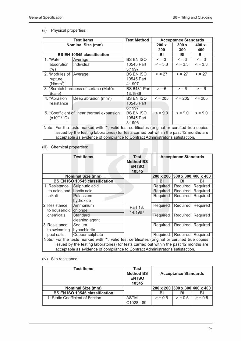
General Specification B6 – Tiling and Cladding
67
(ii) Physical properties:
Test Items Test Method Acceptance Standards Nominal Size (mm) 200 x 300 x 400 x
200 300 400 BS EN 10545 classification BI BI BI 1. *Water Average BS EN ISO < = 3 < = 3 < = 3 absorption Individual 10545 Part < = 3.3 < = 3.3 < = 3.3 (%) 3:1997 2. *Modules of Average BS EN ISO > = 27 > = 27 > = 27 rupture 10545 Part (N/mm2) 4:1997 3. *Scratch hardness of surface (Moh’s BS 6431 Part > = 6 > = 6 > = 6 Scale) 13:1986 4. *Abrasion Deep abrasion (mm3) BS EN ISO < = 205 < = 205 <= 205
resistance 10545 Part 6:1997 5. *Coefficient of linear thermal expansion BS EN ISO < = 9.0 < = 9.0 < = 9.0
(x10-6 / oC) 10545 Part 8:1996 Note: For the tests marked with ‘*’, valid test certificates (original or certified true copies
issued by the testing laboratories) for tests carried out within the past 12 months are acceptable as evidence of compliance to Contract Administrator’s satisfaction.
(iii) Chemical properties:
Test Items Test Acceptance Standards Method BS EN ISO 10545 Nominal Size (mm) 200 x 200 300 x 300 400 x 400 BS EN ISO 10545 classification BI BI BI 1. Resistance Sulphuric acid Required Required Required
to acids and Lactic acid Required Required Required alkali Potassium Required Required Required hydroxide 2. Resistance Ammonium Part 13, Required Required Required to household chloride 14:1997 chemicals Standard Required Required Required cleaning agent 3. Resistance Sodium Required Required Required to swimming hypochlorite pool salts Copper sulphate Required Required Required Note: For the tests marked with ‘*’, valid test certificates (original or certified true copies
issued by the testing laboratories) for tests carried out within the past 12 months are acceptable as evidence of compliance to Contract Administrator’s satisfaction.
(iv) Slip resistance:
Test Items Test Method BS Acceptance Standards EN ISO 10545 Nominal Size (mm) 200 x 200 300 x 300 400 x 400 BS EN ISO 10545 classification BI BI BI 1. Static Coefficient of Friction ASTM - > = 0.5 > = 0.5 > = 0.5 C1028 - 89
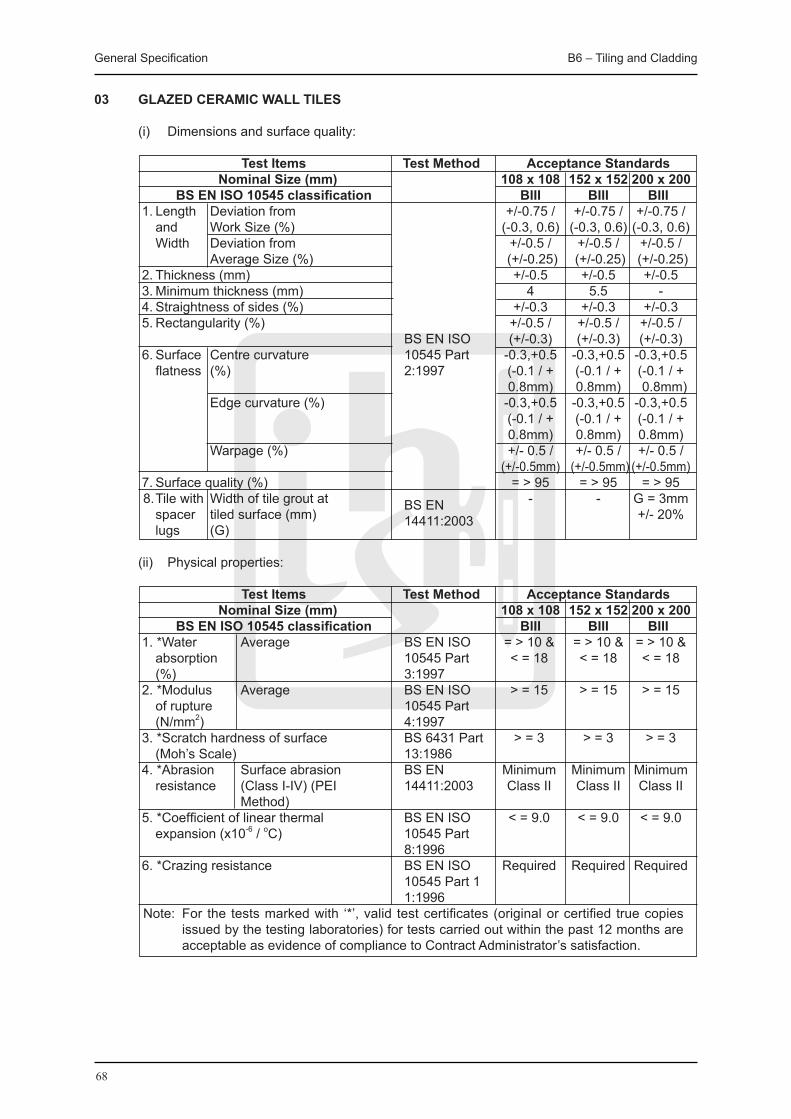
General Specification B6 – Tiling and Cladding
68
03 GLAZED CERAMIC WALL TILES
(i) Dimensions and surface quality:
Test Items Test Method Acceptance Standards Nominal Size (mm) 108 x 108 152 x 152 200 x 200 BS EN ISO 10545 classification BIII BIII BIII 1. Length Deviation from +/-0.75 / +/-0.75 / +/-0.75 /
and Work Size (%) (-0.3, 0.6) (-0.3, 0.6) (-0.3, 0.6) Width Deviation from +/-0.5 / +/-0.5 / +/-0.5 / Average Size (%) (+/-0.25) (+/-0.25) (+/-0.25) 2. Thickness (mm) +/-0.5 +/-0.5 +/-0.5 3. Minimum thickness (mm) 4 5.5 - 4. Straightness of sides (%) +/-0.3 +/-0.3 +/-0.3 5. Rectangularity (%) +/-0.5 / +/-0.5 / +/-0.5 / BS EN ISO (+/-0.3) (+/-0.3) (+/-0.3) 6. Surface Centre curvature 10545 Part -0.3,+0.5 -0.3,+0.5 -0.3,+0.5 flatness (%) 2:1997 (-0.1 / + (-0.1 / + (-0.1 / + 0.8mm) 0.8mm) 0.8mm) Edge curvature (%) -0.3,+0.5 -0.3,+0.5 -0.3,+0.5 (-0.1 / + (-0.1 / + (-0.1 / + 0.8mm) 0.8mm) 0.8mm) Warpage (%) +/- 0.5 / +/- 0.5 / +/- 0.5 / (+/-0.5mm) (+/-0.5mm) (+/-0.5mm) 7. Surface quality (%) = > 95 = > 95 = > 95 8. Tile with Width of tile grout at BS EN - - G = 3mm spacer tiled surface (mm) 14411:2003 +/- 20% lugs (G)
(ii) Physical properties:
Test Items Test Method Acceptance Standards Nominal Size (mm) 108 x 108 152 x 152 200 x 200 BS EN ISO 10545 classification BIII BIII BIII 1. *Water Average BS EN ISO = > 10 & = > 10 & = > 10 & absorption 10545 Part < = 18 < = 18 < = 18 (%) 3:1997 2. *Modulus Average BS EN ISO > = 15 > = 15 > = 15 of rupture 10545 Part (N/mm2) 4:1997 3. *Scratch hardness of surface BS 6431 Part > = 3 > = 3 > = 3 (Moh’s Scale) 13:1986 4. *Abrasion Surface abrasion BS EN Minimum Minimum Minimum resistance (Class I-IV) (PEI 14411:2003 Class II Class II Class II Method) 5. *Coefficient of linear thermal BS EN ISO < = 9.0 < = 9.0 < = 9.0 expansion (x10-6 / oC) 10545 Part 8:1996 6. *Crazing resistance BS EN ISO Required Required Required 10545 Part 1 1:1996 Note: For the tests marked with ‘*’, valid test certificates (original or certified true copies
issued by the testing laboratories) for tests carried out within the past 12 months are acceptable as evidence of compliance to Contract Administrator’s satisfaction.

General Specification B6 – Tiling and Cladding
69
(iii) Chemical properties:
Test Items Test Acceptance Standards Method BS EN ISO 10545 Nominal Size (mm) 108 x 108 152 x 152 200 x 200 BS EN ISO 10545 classification BIII BIII BIII 1. *Resistance Hydrochloric acid Minimum Minimum Minimum to acids and Class B Class B Class B alkali Citric acid Minimum Minimum Minimum Class B Class B Class B Potassium Minimum Minimum Minimum hydroxide Class B Class B Class B 2. *Resistance Ammonium chloride Minimum Minimum Minimum to household Class B Class B Class B chemicals Standard cleaning Part Minimum Minimum Minimum agent 13,14:1997 Class B Class B Class B 3. *Resistance Sodium Minimum Minimum Minimum to swimming hypochlorite Class B Class B Class B pool salts Copper sulphate Minimum Minimum Minimum Class B Class B Class B 4. *Resistance Methylene blue Minimum Minimum Minimum to staining Class B Class B Class B Potassium Minimum Minimum Minimum permanganate (See Note 2) Class B Class B Class B Note: 1. For the tests marked with ‘*’, valid test certificates (original or certified true copies issued
by the testing laboratories) for tests carried out within the past 12 months are acceptable as evidence of compliance to Contract Administrator’s satisfaction;
2. The cleaning agent used is “Bathroom Magiclean” available in supermarkets.
04 GLASS MOSAIC TILES
(i) Dimensions and surface quality:
Test Items Test Method Acceptance Standards Nominal Size (mm) 20 x 20 1. Length & Deviation from Work +/- 2.0 Width Size (%) 2. Thickness (%) +/- 10 3. Minimum thickness (mm) BS EN ISO 4 4. Surface Centre curvature (%) 10545-2:1997 +/- 1.0 flatness Edge curvature (%) +/- 1.0 5. Surface > = 95 quality (%)

General Specification B6 – Tiling and Cladding
70
(ii) Physical properties:
Test Items Test Method Acceptance Standards Nominal Size (mm) 20 x 20 1. *Water Average BS EN ISO < = 3 absorption 10545-3:1997 (%) 2. *Modules of Average BS EN ISO > = 27 rupture 10545-4:1997 (N/mm2) 3. *Scratch hardness of surface (Moh’s BS 6431 Part > = 6 Scale) 13:1986 4. *Coefficient of linear thermal expansion BS EN ISO < = 9.0 (x10-6 / oC) 10545-8:1996 Note: For the tests marked with ‘*’, valid test certificates (original or certified true copies
issued by the testing laboratories) for tests carried out within the past 12 months are acceptable as evidence of compliance to Contract Administrator’s satisfaction.
(iii) Chemical properties:
Test Items Test Method Acceptance Standards Nominal Size (mm) 20 x 20 BS EN ISO 10545 classification BIII 1. *Resistance Sulphuric acid Required to acids and Lactic acid Required alkali Potassium hydroxide Required
2. *Resistance Ammonium chloride Required to household Standard cleaning BS EN ISO Required
chemicals agent 10545-13:1997 3. *Resistance Sodium hypochlorite Required to swimming Copper sulphate Required pool salts Note: For the tests marked with ‘*’, valid test certificates (original or certified true copies
issued by the testing laboratories) for tests carried out within the past 12 months are acceptable as evidence of compliance to Contract Administrator’s satisfaction.

General Specification B6 – Tiling and Cladding
71
05 TILE ADHESIVE
Test Items Test Method Acceptance Standards Remarks 1. Tensile Adhesion BS EN 12004:2001 > = 950N for 14 days curing Laboratory Strength Type 1 cement under laboratory condition. Condition: 20 base, Class AA. > = 560N for 7 days curing ± 2 °C & 45 to under laboratory condition 75% Relative followed by 7 days immersion Humidity. in water. 2. Shear Adhesion Both thin-bed & > = 8.9kN for 14 days curing Strength thick-bed fixing under laboratory condition. > = 4.5kN for 7 days curing under laboratory condition followed by 7 days immersion in water. > = 4.5kN for 7 days curing under laboratory condition followed by 7 days at temperature of 100 ± 2 °C. 3. Adjustability > = 730N for 5 minutes. > = 450N for 10 minutes. 4. Open Time > = 20 minutes. 5. Pull-off See below See below for Compatibility the scope of Test Pull-off Compatibility Test. See below for information to be included in test report.
(i) Method statement for checking the adhesion between tile and tile adhesive (for 400 x 400 x 9.5mm homogeneous wall tile or 200 x 200 x 7mm ceramic glazed wall tile)
(a) The sample shall be cement-based comply with BS EN 12004:2007, Type 1, Class AA, both thin-bed and thick-bed fixing;
(b) The sample shall be subjected to tests of Tensile Adhesion Strength, Shear Adhesion Strength, Adjustability and Open Time with a bed of an adhesive of 1.5 mm thickness and Pull-off Compatibility Test with an adhesive not exceeding 3 mm in final bed thickness. A notched trowel shall be used for Adjustability Test;
(c) The sample shall be subjected to tests of Tensile Adhesion Strength and Open Time with a bed of an adhesive of 6 mm thickness and Adjustability with a solid bed of 1.5 mm thickness. A plain trowel shall be used for Adjustability Test;
(d) Cast a mass concrete wall grade 35/20 of 200 mm thick (for 400 x 400 x 9.5 mm homogeneous wall tile) or construct the panel wall partitions selected to be used in the Contract. The dimensions of the wall to be determined by the commercial laboratory;
(e) Select a tile specimen 400 x 400 mm for homogeneous tile and cut it into four tiles of 200 x 200 mm, or select four specimens of 200 x 200 mm ceramic glazed wall tile;
(f) Fix the four tiles of 200 x 200 mm vertically without additional support according to the manufacturer’s specification to the mass concrete wall or panel wall partition as instructed. The interval between applying tile adhesive and placing tiles is not more than 5 minutes. Record the extent to which slip occurs per the first minute after placing tile specimen. The tile specimens are fixed by adhesive tape to prevent further slip;
Mean Tens i le Adhes ion Strength required to pull-off adhesive applied between 200 x 200 x 7mm ceramic glazed wall tiles and panel wall partition with moisture sealer/off-formed concrete after the installation of tiles lapsed for 28 days: Not less than 0.168N/mm2. Mean Tens i le Adhes ion Strength required to pull-off adhesive applied between homogeneous wall tile and off-formed concrete: Not less than 0.168N/mm2.
General Specification B6 – Tiling and Cladding
72
(g) Carry out a Pull-off Test to the tile on 28 days after fixing; (h) Attach an aluminium/steel dolly onto the surface of the tile by a suitable adhesive resin; (i) Use strong adhesive tape to fix the position of dolly until strength of the resin is
developed as advised by the resin manufacturer; (j) Connect the dolly to the Pull-off Test device. The pull-off equipment shall be capable of
increasing the load steadily without jerking at a rate of 5 mm/min to 6 mm/min, and must be provided with a measurement device which shall retain the maximum force exerted, the so called failure load to the nearest 0.01KN. The measurement inaccuracy of the equipment must be less than 2%, in accordance with accuracy Grade 2 of BS EN ISO 7500-1:2004;
(k) Apply a tensile force gradually by the device; (l) Record the failure force, location of failure and any other observations or abnormalities; (m) Record the force from the readout unit; (n) Repeat steps vii to xiii until Pull-off Tests to all four tiles are completed; (o) Take photographs; (p) Pull-off Compatibility Test; (q) Pull-off Compatibility Test shall be performed against the panel wall partitions with
moisture sealer for those panel partitions selected to be used in the Contract; (r) Pull-off Compatibility Test shall be performed against off-form concrete of grade 35/20; (s) Supplier should advise the waiting time for the Pull-off Compatibility Test at the time of
submission. Otherwise, 28 days is adopted; (t) The panel wall partition supplied for test shall be coated with moisture sealer by the panel
wall partition supplier.
(ii) The report for Pull-off Test shall contain the following data and information: (a) The calculated tensile adhesion strength of individual tile and tile adhesive to the nearest
0.001N/mm2; (b) The pull-off load to the nearest 0.01kN; (c) The type of failure; (d) The area of tile specimen to the nearest 1 x 1mm; (e) The area of the test piece tile to the nearest 1 x 1mm (400 x 400mm tile cut into four
pieces of tiles); (f) The mean tensile adhesion strength of four individual tensile adhesion strength to the
nearest 0.001N/mm2; (g) A description of the test piece tile; (h) A description of the tested substrate; (i) The thickness of the tile adhesive bedding; (j) The age of the bedding at the time of testing; (k) A description of the pulling equipment by stating the make, type, test capacity and
measurement range; (l) The size, the thickness and material of the dolly; (m) The type of epoxy resin; (n) The date of the test to the nearest 1mm; (o) The extent of slip occurs to the nearest 1mm; (p) The mixing ratio; (q) The temperature and relative humidity of laboratory condition; (r) Photographs.
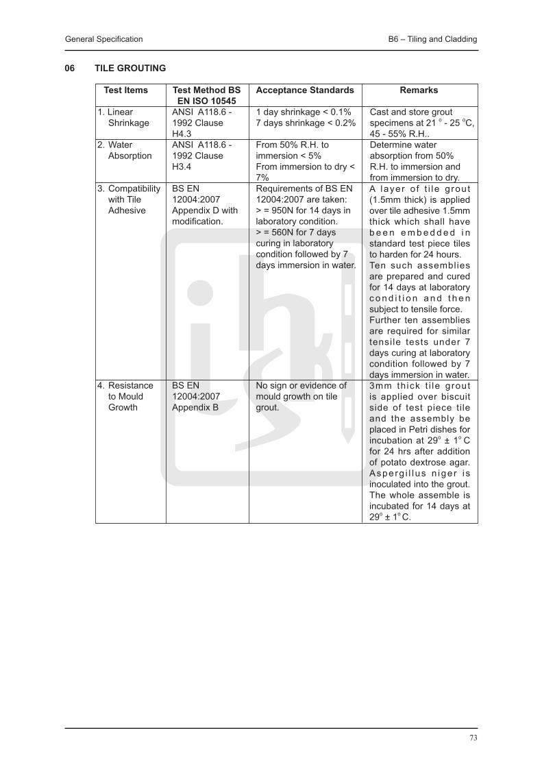
General Specification B6 – Tiling and Cladding
73
06 TILE GROUTING
Test Items Test Method BS Acceptance Standards Remarks EN ISO 10545 1. Linear ANSI A118.6 - 1 day shrinkage < 0.1% Cast and store grout Shrinkage 1992 Clause 7 days shrinkage < 0.2% specimens at 21 o - 25 oC, H4.3 45 - 55% R.H.. 2. Water ANSI A118.6 - From 50% R.H. to Determine water Absorption 1992 Clause immersion < 5% absorption from 50% H3.4 From immersion to dry < R.H. to immersion and 7% from immersion to dry. 3. Compatibility BS EN Requirements of BS EN with Tile 12004:2007 12004:2007 are taken: Adhesive Appendix D with > = 950N for 14 days in modification. laboratory condition. > = 560N for 7 days curing in laboratory condition followed by 7 days immersion in water.
4. Resistance BS EN No sign or evidence of to Mould 12004:2007 mould growth on tile Growth Appendix B grout.
A layer o f t i l e g rou t (1.5mm thick) is applied over tile adhesive 1.5mm thick which shall have b e e n e m b e d d e d i n standard test piece tiles to harden for 24 hours.Ten such assemblies are prepared and cured for 14 days at laboratory c o n d i t i o n a n d t h e n subject to tensile force.Further ten assemblies are required for similar tensi le tests under 7 days curing at laboratory condition followed by 7 days immersion in water.3mm th ick t i le grout is applied over biscuit side of test piece tile and the assembly be placed in Petri dishes for incubation at 29o ± 1o C for 24 hrs after addition of potato dextrose agar. Asperg i l l us n ige r i s inoculated into the grout. The whole assemble is incubated for 14 days at 29o ± 1o C.
General Specification B6 – Tiling and Cladding
74
B6.6 METAL PROFILED / FLAT SHEET CLADDING
01 ISOLATING TAPE Isolating tape shall be a type recommended for the purpose by cladding manufacturer and shall
be applied to those surfaces of supports which would otherwise be in contact with cladding or accessories after fixing.
02 VAPOUR CONTROL LAYER Vapour control layer shall be applied as the work proceeds to ensure continuity. Sides and ends of sheets shall be lapped at not less than 150 mm and sealed with adhesive
tape to pipes, ducts, structural members, etc. which pass through. Tears and punctures shall be checked carefully and shall be sealed with adhesive tape before
covering.
03 INSULATION Insulation shall be kept dry, installed and secured as the work proceeds, leaving no gaps and
without compressing.
04 BREATHER MEMBRANE Insulation shall be laid over as the work proceeds with sides and ends of sheets lapped not
less than 150 mm to shed water away from insulation. Bottom edges shall overlap flashings, gutters, sills, etc. to allow free drainage to the exterior.
05 PROFILE FILLERS Type(s) supplied by cladding manufacturer shall match sheet profile and shall be perforated for
ventilation and drainage of condensation unless specified otherwise. Corrugation cavities shall be closed off by profile fillers from the outside and inside of the
building. Ensuring tight fit, no gaps shall be left. Where sealed laps are specified, fillers shall be bedded in sealant on top and bottom surfaces.
Cavities at hips/valleys shall be closed with blocks cut from standard filler positioned in sawtooth formation. Sealant shall be bedded in, top and bottom, to ensure continuity of seal from block to block.
Fire resisting profile fillers shall be fixed where shown on drawings, leaving no gaps by using
an adhesive recommended by the filler manufacturer.
06 FIXING Openings in sheets shall be cut for outlets, vent pipes, flues, etc. to the minimum size
necessary.
Sheets shall be laid with exposed joints of side laps away from prevailing wind. Ends of sheets and end laps shall be fully supported with fixings at top of lap.
All holes shall be formed by drilling. When not specified otherwise, fastenings recommended
by cladding manufacturer shall be used. Drilling swarf, dust, etc. shall be removed before fixing sheets into position. On completion, fastenings shall be checked and adjusted as necessary to ensure the cladding
General Specification B6 – Tiling and Cladding
75
is secure and watertight but not buckled or distorted.
Fixing holes shall be drilled in the crown of corrugations for roofing, and in the trough of corrugations for cladding. Holes shall be drilled at 2 mm larger than bolts or screw, and at not less than 40 mm from edges of sheets.
Movement joints shall be provided in all lengths of roofing or cladding over 45 m, with one joint for lengths up to 75 m and one for every additional 30 m. Movement joint cover shall be fixed to sheets at one side only.
07 FLASHINGS / TRIMS Vertical and sloping flashings/trims: End laps shall be the same as for adjacent sheeting.
Horizontal flashings/trims: End laps shall be 150 mm and sealed.
08 SEALING LAPS Sealant, as recommended by sheet manufacturer, shall be carefully applied to dry surfaces to
provide fully sealed draught and waterproof joints.
End laps between plastics profiled sheets shall be sealed with two strips of sealing tape, one along each edge of lap.

76

77
PaintingB7
General Specification B7 – Painting
78
B7 PAINTING
B7.1 GENERAL All paints and decorative materials shall be of approved type, brand and colour.
01 SELECTION OF COLOURS FOR PAINTWORK
The colours of paintwork shall be provisionally selected by the Contract Administrator from a catalogue showing the range of colours offered by the manufacturers.
Trial panels shall be painted in each of the colours provisionally selected by the Contract Administrator. Each trial panel shall be 1 m x 1 m and shall be painted with the complete paintwork system.
Trial panels shall be protected from damage and shall be left in position until the Contract Administrator instructs their removal.
02 STORAGE OF MATERIALS
Paint and associated materials shall be stored in a dry weatherproof and covered store. The store shall be maintained in a cool and well-ventilated condition.
Tins of paint shall be labelled as being for external use, internal use, undercoating and finishing, as appropriate, and shall be protected from exposure to conditions that may adversely affect the material. Paint and associated materials shall be stored in accordance with the manufacturers’ recommendations and shall not be used after the recommended shelf life has been exceeded.
No smoking shall be permitted where flammable paints or solvents are used. Appropriate signs should be displayed at conspicuous place as appropriate.
03 PRECAUTIONARY MEASURES
Lead based primers and calcium primers shall not be applied by spraying.
Respirators, which supply clean air during blast cleaning, paint spraying or in a situation where toxic fumes are generated, shall be worn.
Precautions shall be taken to avoid skin and eye contact with paints and their solvents. All precautionary measures as recommended by the paint manufacturers shall be followed.
B7.2 MATERIALS
01 GENERAL All painting shall be applied in strict compliance with approved paint manufacturers’
recommendation, and shall be compatible with each other.
02 PRIMING PAINTS
For synthetic finishing paints on internal and external woodwork, aluminium primer to BS 4756:1988, Type 1 shall be used.
For synthetic finishing paints on internal and external metalwork, zinc phosphate primer or metallic zinc-rich primer to BS 4652:1995 Type 2, as specified shall be used.
For synthetic or non-toxic paints on galvanized metal surfaces, an approved etching primer with a zinc-chromate base shall be used.
General Specification B7 – Painting
79
For polyurethane paint on internal and external metalwork, polyurethane red lead primer shall be used.
03 SEALERS
For plaster, masonry and the like, sealers shall be an approved stabilizing solution or oil-based plaster sealer.
04 ANTI-MOULD LIqUID Anti-mould liquid shall be an approved fungicidal solution.
05 WATER REPELLANT LIqUID Water repellent liquid shall be silicone or other approved water repellent.
06 EMULSION PAINT
Emulsion paint shall be acrylic, plastic, vinyl or latex emulsions and shall be approved material by Contract Administrator.
07 TEXTURED PAINT Textured emulsion paint shall be acrylic based emulsion paint textured with a finely dispersed
aggregate approved by the Contract Administrator.
External textured paint shall be an approved heavy duty masonry paint incorporating fine aggregate filler.
08 ANTI-MOULD ACRYLIC EMULSION PAINT
Anti-mould emulsion paint shall be acrylic based emulsion incorporating an approved fungus resistant chemical.
09 MULTI-COLOUR PAINT
Multi-colour paint shall be an approved brand comprising a base and hardwearing top coat incorporating a pigmented splatter coat used as recommended by the manufacturer.
10 CEMENT PAINT
Cement paint shall be waterproof cement base paint supplied in drums and shall not be mixed with lime or other adulterants.
11 FIRE RETARDANT PAINT
Fire retardant paint shall be paints which, when used alone or in conjunction with other paints applied to combustible substrates in accordance with a manufacturer’s tested system, achieve Class 1 spread of flame rating to BS 476:Pt. 7:1997.
12 SYNTHETIC PAINT
Unless expressly specified otherwise, all paint for internal and external use shall be synthetic paint of alkyd resin base combined with drying oils and pigments. Undercoats and finishing coat shall be of properly matching type and the finishing coat shall give a hard gloss finish or as otherwise specified.
General Specification B7 – Painting
80
13 POLYURETHANE PAINT Polyurethane paint shall be of the Two Pack Type and part of an approved system.
14 BLACK BITUMASTIC PAINT
Black bitumastic paint shall be tar base paint complying with the requirements of BS 1070:1993, Type B (quick drying).
15 BLACK BITUMEN COATING SOLUTION Black bitumen coating solution shall be to BS 3416:1991, Type 1 for general purposes.
16 METALLIC PAINT
Metallic paint shall compose of acrylic resin solution base mixed with finely divided aluminium to give a bright finish, or finely divided copper or copper alloy to give a bronze finish.
17 MARKING PAINT FOR CARPARK FLOORS Marking paint shall be an approved purpose made synthetic non-skid marking paint to BS EN
1871:2000, BS EN 1436:1998, with a drying time not exceeding 30 minutes.
18 NON-TOXIC PAINT
Non toxic paint for use on water tanks, water collecting roofs etc. shall be proprietary brands as approved by the UK National Water Council and one of the following types:
(i) Petroleum or asphaltic bitumen based coatings, or (ii) Epoxy based coatings. 19 WOOD PRESERVATIVE
Wood preservative shall offer complete protection against termites, wood boring insects, fungi, woodrot and decay. It shall be an approved proprietary brand exterior grade, where completely concealed or not decorated, and colourless, coloured or suitable for overpainting where likely to be exposed or be in contact with a painted finish.
20 STAIN
Stain for woodwork shall be an approved water or spirit stain suitable for use under varnish or wax polish. Self finished stains shall be an approved proprietary make.
21 VARNISH Varnish shall be one of the following types: (i) Copal Varnish shall be No. 1 Extra Pale quality for internal use only. (ii) Synthetic Varnish shall be the Long Linseed Oil Alkyd type for internal or external use. (iii) Polyurethane Varnish for internal or external use shall be either: (a) Moisture Cure Oil Modified One Pack Type, or (b) ISO Cure Two Pack Type.
22 WAX POLISH Wax polish for floors, furniture and joinery shall be an approved proprietary brand.
General Specification B7 – Painting
81
23 CELLULOSE LACqUER
Cellulose lacquer shall be an approved brand.
B7.3 WORKMANSHIP
01 GENERAL
Surfaces, fittings, furniture and the like shall be protected by suitable and approved means.
“Wet Paint” signs in Chinese and English shall be exhibited and protective barrier shall be provided where necessary.
All surfaces shall be kept clean and free from dust during coating and drying.
All splashes shall be removed and cleaned off while work is in progress. Damage shall be made good, and work, and all areas in which work is executed, shall be left clean and perfect on completion.
Painting generally shall be in accordance with BS 6150:2006 and BS 8000:Pt. 12:1969.
(i) Works shall not be carried out in wet humid or foggy weather, direct sunlight, or on surfaces which are not thoroughly dry, or if there is excessive dust in the air.
(ii) All holes, cracks and other defects in surfaces shall be made good prior to painting. (iii) Each coat shall be brushed well into the surface so that every part, including joints,
junctions, angles, etc., is adequately covered. Excessive or uneven thickness of paint film, particularly at edges, angles and junction shall be avoided.
(iv) Before applying coatings, moisture content of the substrate shall be checked to avoid adversely affecting the completed work. Coatings shall only be applied to clean, dry surfaces after any previous coatings have hardened, and have been rubbed down smooth with fine glass paper.
(v) Successive coats of paint shall be of slightly differing tints, and the intercoating time shall not exceed the limits recommended by the paint manufacturers.
(vi) Coatings shall be applied with approved bristle brushes of suitable size. Flat wall brushes shall not be less than 150 mm wide.
(vii) Rollers, cloths or gloves shall not be used unless ordered or approved by the Contract Administrator.
(viii) Mechanical spraying machines shall not be used unless ordered or approved by the Contract Administrator. When mechanical spray painting is ordered or permitted, the priming coat (or first undercoat, if no priming coat) shall be applied by brush.
(ix) Where required, surfaces which become inaccessible shall be primed and painted prior to fixing.
(x) All articles of ironmongery, hardware, etc. shall be removed before painting and replaced with matching screws (and plugs, if required,) of suitable size, after completion. Everything shall be left clean and completely free from all paint stains, splashes, etc.
(xi) Weather stripping on metal windows or doors shall not be painted. (xii) Coated surfaces shall be touched up on completion, when ordered. (xiii) Paint sample panels shall be prepared if necessary for Contract Administrator’s approval
before carrying out work.
General Specification B7 – Painting
82
B7.3.1 TREATMENT OF EXISTING SURFACE
Existing decoration which is in poor condition or shall be replaced by a different type of decoration shall be completely stripped off. After stripping the existing decoration, surfaces shall be prepared as required for the type of decoration to be applied.
All concrete surfaces to receive paint shall be dry at the time of application. Sufficient drying time shall be allowed either after construction or after wet preparation methods, to satisfy one of the following requirements:
(i) Moisture meter readings shall be consistently less than 5% (concrete scale). (ii) There shall be no retained moisture behind polythene taped to the concrete for 24 hours. (iii) Internal humidity measurements within concrete shall be < 75% (e.g. Seared probe).
Prior to applying the paint to new surfaces, sample area not less than 5 m2 shall be prepared on the structure to be painted.
Actual consumption in litres/m2 of the various coats of the paint system in the test area shall be recorded, in order that due allowance may be made for rough, irregular or exceptionally absorbent concrete, or render.
When the paint system has cured for 14 days, a test on surface adhesion shall be made.
In the absence of satisfactory bond strength results, the concrete surface shall be cleaned using high pressure water jetting followed by re-application and re-testing of the coating.
Coatings shall only be applied during favourable weather periods, when rainfall is not expected for the following 12 hours.
The dew point shall be at least 5ºC lower than the temperature of the concrete surface before painting can commence.
Painting, using water based paints, shall not commence whilst the relative humidity is above 85% or where it may be expected to exceed 90% during the 12 hour curing period.
Primers, undercoats and finish coats shall be applied in accordance with manufacturers’ instructions using brush, roller, spray or other technique to achieve the desired surface finish. Brush application of primers is the preferred method for working paint into concrete pores.
Where brush or roller techniques are used, the brushes or roller beads shall be used for the day only and then discarded. The equipment shall not be cleaned for reuse, owing to the risk of solvent/water dilution.
Where spray equipment is used, all cleaning fluid shall be purged from the lines using undiluted paint. All such contaminated paint used for purging lines shall be discarded and not be used in the works.
Where two-component materials are used, each component shall be thoroughly stirred before mechanically mixing the whole units together; part batches shall not be used. The exception is where airless spray equipment is used, incorporating a nozzle mixing device.
For multiple coat applications, manufacturers stated minimum and maximum overcoating times shall not be breached for the prevailing weather conditions.
For multiple coat applications, successive coats shall have slightly different colour shades to assist in achieving uniform coverage.
General Specification B7 – Painting
83
B7.3.2 PREPARATION OF EXISTING DECORATED SURFACES
All dust, dirt, stains, efflorescence, grease and loose material shall be removed and, unless otherwise specified, existing decorated surfaces shall be prepared for decoration as follows:
(i) Lime washed or whitened surfaces shall be scraped, broomed down, stopped, applied and brought forward bare spots with new material.
(ii) Chinese distempered washable sealer or non-washable distempered surfaces shall be stripped off completely, washed down, stopped, sealed and prepared to receive emulsion paint or other paint as specified.
(iii) Emulsion or textured emulsion painted surfaces shall be scraped, washed down, stopped, and brought forward bare spots with new material.
(iv) Cement painted and external textured painted surfaces shall be scraped, washed down, stopped, brought forward bare spots with new material and surface shall be dampened immediately prior to painting.
(v) Synthetic painted surfaces other than metal or wood shall be scraped, washed down, stopped, rubbed down and applied with primer to and brought forward bare spots with undercoat.
(vi) Black bituminous coated surfaces shall be spot primed bare areas with black bituminous coating.
B7.3.3 TREATMENT OF METALWORK
01 PAINTED NON-GALVANISED IRON AND STEEL
Painted non-galvanised iron and steel surfaces shall be washed down, scraped, chipped off, and wire brushed to remove all scale and rust, then rubbed down, applied with rust inhibitor and primer to bare areas or such additional areas as directed and brought forward with undercoat.
02 PAINTED ZINC-SPRAYED OR GALVANISED IRON AND STEEL
Painted zinc-sprayed or galvanised iron and steel surfaces shall be washed down, scraped and removed from all scale and rust, then rubbed down and applied with calcium primer and brought forward bare spots with undercoat.
B7.3.4 TREATMENT OF WOODWORK
01 SYNTHETIC PAINTED SURFACES Synthetic painted surfaces shall be washed down, scraped, rubbed down, knotted, primed and
stopped and brought forward bare spots with undercoat.
02 POLYURETHANE OR COLD CURE EPOXY PAINTED SURFACES
Polyurethane or cold cure epoxy painted surfaces shall be washed down, scraped, rubbed down, stopped and applied with epoxy filler and brought forward bare spots with undercoat.
03 VARNISHED SURFACES
Varnished surfaces shall be washed down, scraped and rubbed down and brought forward bare spots with varnish.
04 WAXED OR LACqUERED SURFACES OTHER THAN WAXED FLOORS
Waxed or lacquered surfaces other than waxed floors shall be rubbed down, filled, and again rubbed down to produce a smooth surface ready for rewaxing or relacquering.
05 WAXED FLOORS Waxed floors surfaces shall be cleaned with wire wool or sanded down as specified.

General Specification B7 – Painting
84
B7.3.5 PREPARATION OF PLASTERED AND RENDERED SURFACES
All plastered and rendered surfaces shall be thoroughly washed as necessary, broomed down and stopped.
“Washing” shall mean removal by washing with clean water of all materials not absorbed into the underlying surfaces.
“Brooming down” shall mean thorough dry brushing of any surface with a stiff broom or brush as to remove all cobwebs, dust or loose particles of previous finishes.
B7.3.6 PRIMING
Primer shall be worked into surface, joints, angles and end grain.
Priming coats shall be of adequate thickness and suit the surface porosity.
Any primed surfaces that have deteriorated on site or in transit shall be touched up or re-primed.
Priming coats on new work shall be applied before the articles are fixed in position.
Primer to metal surfaces shall be applied on the same day as they have been cleaned.
‘Wash’ or ‘etch’ priming coats shall be allowed to harden before applying subsequent priming coats.
B7.3.7 UNDERCOATING
Undercoats shall be applied in an even film over all surfaces. Uneven thicknesses at edges and angles shall be avoided.
If the undercoating of a particular painting system is only available in white, an additional finishing coat shall be applied in lieu of a second undercoat.
B7.3.8 FINISHING COAT
Finishing coats shall be applied in an even film over all surfaces. Brush marks, sags, runs and other defects shall be avoided.
Where two hard gloss finishing coats are specified, the second coat shall be applied within 48 hours of the first coat.
Key shall be provided between coats by rubbing down with medium/fine glass paper.
B7.3.9 ANTI-MOULD LIqUID
Surfaces subject to mould or similar growth, shall be washed down with one coat of anti-mould liquid before preparation of surface for decoration. Surfaces shall be entirely clean of old mould growth and spores.
B7.3.10 WATER REPELLANT LIqUID
Surfaces shall be brushed, cleaned down and applied with one coat of water repellant liquid in accordance with the manufacturer’s recommendations.

General Specification B7 – Painting
85
B7.3.11 CEMENT PAINT
Before applying cement paint to absorbent surfaces, the surfaces shall be thoroughly damped to provide even suction. Cement paints shall be used within one hour of mixing. A minimum drying time of 12 hours shall be allowed between coats.
B7.3.12 WOOD PRESERVATIVE
Wood preservative shall be applied over entire surface of timber. The timber shall have the correct moisture content before application of the preservative. Treatment shall comply with the manufacturer’s recommendations, and shall be carried out after cutting to size. Treated timber shall be stacked to dry out before priming and fixing.
B7.3.13 BLACK BITUMEN COATING SOLUTION
Coating which is to receive plaster, rendering or screeds shall be blinded with clean, sharp sand while still tacky. The final covering shall be laid as soon as possible after the black bitumen coating.
B7.3.14 WAX POLISH
On joinery and furniture, wax polish shall be applied with a soft cloth and a minimum drying time of 4 hours shall be allowed between coats. Surface shall be brushed with a soft brush to obtain an eggshell finish. On floors, wax polish shall be applied with weighted felt pad or electric polisher.
B7.3.15 CELLULOSE LACqUER
A hard, high gloss finish free from marks and imperfections shall be produced by applying undercoats, rubbing down with “flour-grade” glass paper and applying final coat and polishing.
B7.4 PAINTING TO PIPE WORKS
The contractor shall submit proposal of painting system including type of paint coat/primer, painting procedures etc, to the Contract Administrator for approval prior to commencement of work. All paints shall be prepared and applied in accordance with the manufacturer’s recommendations.
Painting to pipe works shall strictly follow the specified or approved painting system, which is compatible with the existing coating. The colour of the finishing coat should match the surrounding surface with distinguishing colour code bands and flow arrows in the specified colour scheme as directed.
All galvanized metal surfaces shall be properly etch-primed to ensure correct adhesion of the paint to the surface. Material shall be as recommended by the paint manufacturers. Painting to galvanized surfaces shall be one coat of primer, one undercoat and two finishing coats of synthetic paint or other paint system subject to the Contract Administrator’s approval.
Prior to painting, all metallic surfaces except galvanized surfaces shall be thoroughly scraped and wire brushed as necessary to remove scale, rust and swarf. All metallic and uPVC surfaces shall then be solvent cleaned to remove all oil, grease and dirt.
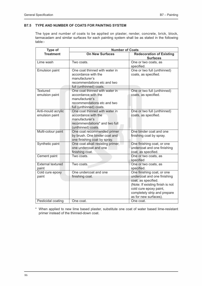
General Specification B7 – Painting
86
B7.5 TYPE AND NUMBER OF COATS FOR PAINTING SYSTEM
The type and number of coats to be applied on plaster, render, concrete, brick, block, tarmacadam and similar surfaces for each painting system shall be as stated in the following table:-
Type of Number of Coats Treatment On New Surfaces Redecoration of Existing Surfaces Lime wash Two coats. One or two coats, as specified. Emulsion paint One coat thinned with water in One or two full (unthinned) accordance with the coats, as specified. manufacturer’s recommendations etc and two full (unthinned) coats. Textured One coat thinned with water in One or two full (unthinned) emulsion paint accordance with the coats, as specified. manufacturer’s recommendations etc and two full (unthinned) coats. Anti-mould acrylic One coat thinned with water in One or two full (unthinned) emulsion paint accordance with the coats, as specified. manufacturer’s recommendations* and two full (unthinned) coats. Multi-colour paint One coat recommended primer One binder coat and one by brush. One binder coat and finishing coat by spray. one finishing coat by spray. Synthetic paint One coat alkali resisting primer, One finishing coat, or one one undercoat and one undercoat and one finishing finishing coat. coat, as specified. Cement paint Two coats. One or two coats, as specified External textured Two coats. One or two coats, as paint specified. Cold cure epoxy One undercoat and one One finishing coat, or one paint finishing coat. undercoat and one finishing
coat, as specified. (Note: If existing finish is not cold cure epoxy paint, completely strip and prepare as for new surfaces). Pesticidal coating One coat. One coat. * When applied to new lime based plaster, substitute one coat of water based lime-resistant
primer instead of the thinned-down coat.
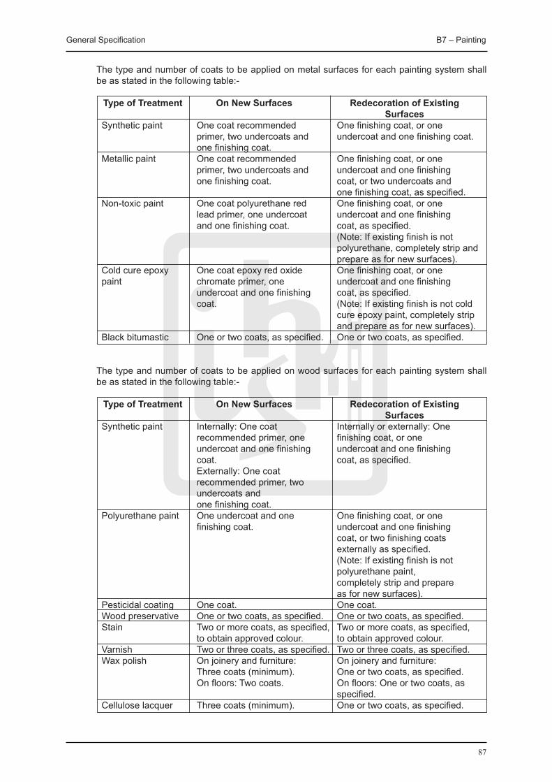
General Specification B7 – Painting
87
The type and number of coats to be applied on metal surfaces for each painting system shall be as stated in the following table:-
Type of Treatment On New Surfaces Redecoration of Existing Surfaces
Synthetic paint One coat recommended One finishing coat, or one primer, two undercoats and undercoat and one finishing coat. one finishing coat. Metallic paint One coat recommended One finishing coat, or one primer, two undercoats and undercoat and one finishing one finishing coat. coat, or two undercoats and one finishing coat, as specified. Non-toxic paint One coat polyurethane red One finishing coat, or one lead primer, one undercoat undercoat and one finishing and one finishing coat. coat, as specified. (Note: If existing finish is not polyurethane, completely strip and prepare as for new surfaces). Cold cure epoxy One coat epoxy red oxide One finishing coat, or one paint chromate primer, one undercoat and one finishing undercoat and one finishing coat, as specified. coat. (Note: If existing finish is not cold cure epoxy paint, completely strip and prepare as for new surfaces). Black bitumastic One or two coats, as specified. One or two coats, as specified.
The type and number of coats to be applied on wood surfaces for each painting system shall
be as stated in the following table:-
Type of Treatment On New Surfaces Redecoration of Existing Surfaces
Synthetic paint Internally: One coat Internally or externally: One recommended primer, one finishing coat, or one undercoat and one finishing undercoat and one finishing coat. coat, as specified. Externally: One coat recommended primer, two undercoats and one finishing coat. Polyurethane paint One undercoat and one One finishing coat, or one finishing coat. undercoat and one finishing
coat, or two finishing coats externally as specified. (Note: If existing finish is not polyurethane paint, completely strip and prepare as for new surfaces). Pesticidal coating One coat. One coat. Wood preservative One or two coats, as specified. One or two coats, as specified. Stain Two or more coats, as specified, Two or more coats, as specified, to obtain approved colour. to obtain approved colour. Varnish Two or three coats, as specified. Two or three coats, as specified. Wax polish On joinery and furniture: On joinery and furniture: Three coats (minimum). One or two coats, as specified. On floors: Two coats. On floors: One or two coats, as specified. Cellulose lacquer Three coats (minimum). One or two coats, as specified.
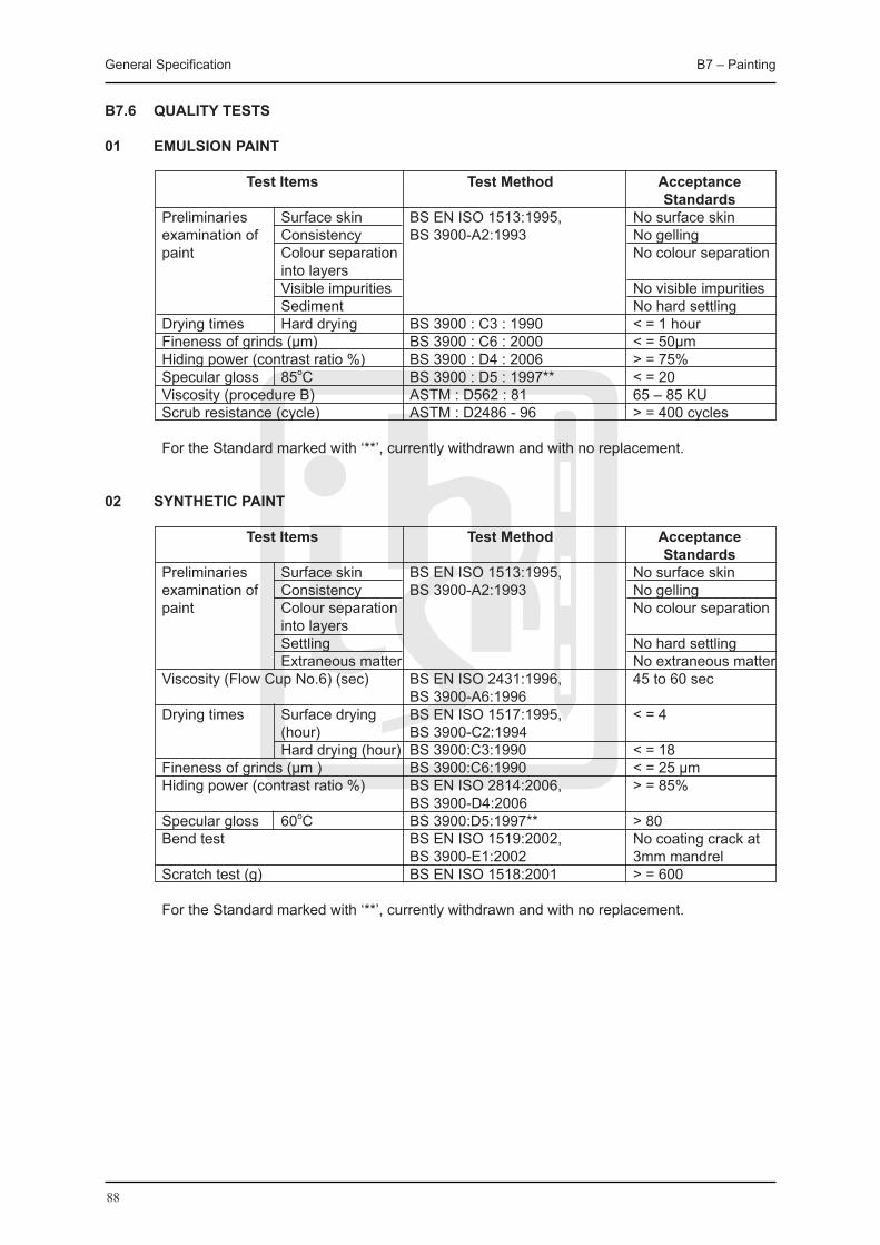
General Specification B7 – Painting
88
B7.6 qUALITY TESTS
01 EMULSION PAINT
Test Items Test Method Acceptance Standards Preliminaries Surface skin BS EN ISO 1513:1995, No surface skin examination of Consistency BS 3900-A2:1993 No gelling paint Colour separation No colour separation into layers Visible impurities No visible impurities Sediment No hard settling Drying times Hard drying BS 3900 : C3 : 1990 < = 1 hour Fineness of grinds (μm) BS 3900 : C6 : 2000 < = 50μm Hiding power (contrast ratio %) BS 3900 : D4 : 2006 > = 75% Specular gloss 85oC BS 3900 : D5 : 1997** < = 20 Viscosity (procedure B) ASTM : D562 : 81 65 – 85 KU Scrub resistance (cycle) ASTM : D2486 - 96 > = 400 cycles For the Standard marked with ‘**’, currently withdrawn and with no replacement.
02 SYNTHETIC PAINT
Test Items Test Method Acceptance Standards Preliminaries Surface skin BS EN ISO 1513:1995, No surface skin
examination of Consistency BS 3900-A2:1993 No gelling paint Colour separation No colour separation into layers Settling No hard settling Extraneous matter No extraneous matter Viscosity (Flow Cup No.6) (sec) BS EN ISO 2431:1996, 45 to 60 sec BS 3900-A6:1996 Drying times Surface drying BS EN ISO 1517:1995, < = 4 (hour) BS 3900-C2:1994 Hard drying (hour) BS 3900:C3:1990 < = 18 Fineness of grinds (μm ) BS 3900:C6:1990 < = 25 μm Hiding power (contrast ratio %) BS EN ISO 2814:2006, > = 85% BS 3900-D4:2006 Specular gloss 60oC BS 3900:D5:1997** > 80 Bend test BS EN ISO 1519:2002, No coating crack at BS 3900-E1:2002 3mm mandrel Scratch test (g) BS EN ISO 1518:2001 > = 600 For the Standard marked with ‘**’, currently withdrawn and with no replacement.

General Specification B7 – Painting
89
03 MULTI-LAYER ACRYLIC PAINT
Test Items Test Method Acceptance Remarks Standards Low Clause 5.5 JIS A No lumps and free Respective coatings Temperature 6910-1988 from separation and of primer coating, Stability aggregation of the main coating and top composing materials. coating are regarded as the samples. Change in Clause 5.6 JIS A ± 15% Respective coatings Consistency 6910-1988 of primer coating, main coating and top coating are regarded as samples. Cracking Clause 5.7 JIS A No cracking shall Resistance due 6910-1988 occur. to Initial Stage Drying Adhesion Clause 5.8 JIS A Standard condition > Strength 6910-1988 = 68.6 N/cm2
Immersion in water > = 49.0 N/cm2 Repeated Clause 5.9 JIS A No peering, cracking Warning and 6910-1988 and blistering and Cooling remarkable discolouration and degradation in luster on the surface. Permeability Clause 5.10 JIS A < = 0.5 ml 6910-1988 Impact Clause 5.11 JIS A Cracking, remarkable Resistance 6910-1988 deformation and peeling shall not occur. Weather ASTM G-53-88 Cracking and peeling The test conditions: Resistance shall not occur and Fluorescent UV the discolouration Lamp: UVA-340 shall be No.3 or over Cycle: 24 hrs UV at in grey scale 60°C according to JIS Total exposure 6910-1988. time: 250 hours Determination BS EN ISO No blistering, loss of The amount of of Resistance to 3231:1998, adhesion, rust sulphur dioxide to be humid BS 3900-F8:1993 staining, change of used in testing is one atmospheres colour, embrittlement litre. containing and other signs of The test cycle to
sulphur dioxide deterioration. be 12 cycles. Resistance to BS EN ISO 2812- Rating 0, no fungal Fungal Growth 2:1995, growth. BS 3900-G8:1993

General Specification B7 – Painting
90
B7.7 VOLATILE ORGANIC COMPOUND CONTENT
The Volatile Organic Compound (VOC) content, in grams per litre, of all paint to be applied on surfaces of building fabrics, building elements and any installations/equipment inside semi-enclosed / enclosed areas of the building shall not exceed the current standard in the Air Pollution Control Ordinance (Cap 311).
01 VOC LIMITS
(i) List I
Regulated paints Maximum limits of VOC content 1. Aluminium roof coatings 250 2. Below-ground wood preservatives 350 3. Bond breakers 350 4. Clear brushing lacquers 650 5. Clear wood finishes (sanding sealers) 150 6. Concrete-curing compounds 350 7. Dry-fog coatings 400 8. Fire-proofing exterior coatings 350 9. Graphic arts (sign) coatings 500 10. Interior stains 250 11. Magnesite cement coatings 450 12. Mastic coatings 300 13. Other architectural coatings 250 14. Pigmented lacquers 275 15. Recycled coatings 250 16. Roof coatings (exposed) 50 17. Roof coatings (non-exposed) 250 18. Shellacs (clear) 730 19. Shellacs (pigmented) 550 20. Specialty primers 350 21. Stains 100 22. Swimming pool repair coatings 340 23. Swimming pool coatings (other) 340 24. Waterproofing concrete or masonry sealers 400 25. Wood preservatives (other) 350
(ii) List II
Regulated paints Maximum limits of VOC content 1. Fire-retardant coatings (clear) 650 2. Flat coatings 50 3. Granite look-alike coatings or 100 textured undercoaters 4. Japans or faux finishing coatings 350 5. Multi-colour coatings 250 6. Non-flat coatings 150 7. Roof primers (bituminous) 350

General Specification B7 – Painting
91
(iii) List III
Regulated paints Maximum limits of VOC content 1. Clear wood finishes (lacquers) 550 2. Clear wood finishes (varnishes) 150 3. Extreme high-gloss coatings for metal 420 4. Fire-retardant coatings (pigmented) 350 5. Floor coatings 250 6. High-temperature industrial maintenance 420 coatings 7. Industrial maintenance coatings 250 8. Metallic pigmented coatings 500 9. Pre-treatment coatings for metal 420 10. Pre-treatment wash primers 420 11. Primers, sealers and undercoaters 200 12. Quick-dry enamels 250 13. Quick-dry primers, sealers and undercoaters 200 14. Rust preventative coatings 400 15. Superior durability solvent-borne coatings for 420 metal 16. Traffic coatings 150 17. Waterproofing sealers 250 18. Zinc-rich industrial maintenance primers 250
The testing method of the VOC content of paint shall be determined by the United States Environmental Protection Agency Method 24.

92

93
B8 Roofing,WaterproofingandLeakageRepair
General Specification B8 – Roofing, Waterproofing and Leakage Repair
94
B8 ROOFING, WATERPROOFING AND LEAKAGE REPAIR
B8.1 MATERIALS
01 MASTIC ASPHALT
Mastic asphalt (rock asphalt) roofing shall not be used for re-roofing projects. In case for roof repair and maintenance, mastic asphalt for asphalt roofing shall comply with BS 6925:1988, Type R988.
02 PROPRIETARY FLEXIBLE SHEET MEMBRANE
Proprietary flexible sheet membrane shall be capable of accommodating unanticipated cracks of up to 0.6mm wide without losing its waterproofing properties, and the properties of the membrane in lap shear and lap peel shall not be less than 110 kN/m2 and 3.3 kN/m respectively at site condition.
Certificates together with complete test reports to substantiate that the materials supplied meet the requirements specified shall be submitted when the material is delivered to Site.
03 PROPRIETARY LIqUID APPLIED MEMBRANE
Proprietary liquid applied, elastomeric waterproofing shall be made of a pitch modified polyurethane, and shall be submitted for approval by the Contract Administrator. The membrane shall be capable of an elongation of not less than 400% to accommodate cracks up to 2mm without losing its waterproofing properties, and its tensile strength shall exceed 1.6 kN/mm². The tear resistance and adhesion strength shall not be less than 12 N/mm and 2.6 N/mm respectively at site condition. It shall be applied in strict accordance with the manufacturer’s instructions.
Certificates together with complete test reports to substantiate that the materials supplied meet the requirements specified shall be submitted when the material is delivered to Site.
04 ISOLATING MEMBRANE
Isolating membrane for asphalt roofing shall be black sheathing felt complying with BS EN 13707:2004, Class 4A(i) and shall weigh at least 17 kg per 810mm wide by 25 m long roll.
05 BITUMEN DRESSING COMPOUND
Bitumen dressing compound for asphalt roofing shall be cut-back bitumen, Grade 25 sec or other grade approved by the Contract Administrator.
06 BITUMINOUS PAINT
Bituminous paint for asphalt roofing shall comply with BS 6949:1991.
07 SAND
Sand for finishing the surface of asphalt roofing shall be fine, clean sand and shall be graded such that 100% passes a 600 μm BS test sieve and 100% is retained on a 300 μm BS test sieve.
08 STONE CHIPPINGS
Stone chippings for asphalt roofing shall be white stone (Baak Shek) chippings and shall be graded such that 100% passes a 5 mm BS test sieve and 100% is retained on a 2.36 mm BS test sieve.
General Specification B8 – Roofing, Waterproofing and Leakage Repair
95
09 REFLECTIVE PAINT
Reflective paint for asphalt roofing shall be a proprietary type approved by the Contract Administrator and shall be a bituminous based aluminium paint or a paint compatible with bituminous surfaces.
10 METAL LATHING
Metal lathing for asphalt roofing shall be zinc coated or stainless steel expanded metal lathing complying with BS EN 13658-1:2005, BS EN 13658-2:2005. The reinforcement shall be at least 10mm short way of mesh and shall be at least 0.46mm thick.
B8.2 MASTIC ASPHALT - WORKMANSHIP
B8.2.1 BACKGROUND / BASES
01 REMOVAL OF EXISTING POLISH Existing polish shall be removed from appropriate areas before carrying out repairs to existing
mastic asphalt. Loose dust shall be removed by washing or vacuuming. A suitable stripping solution shall be applied to and slurry shall be removed from surface, all in accordance with manufacturer’s recommendations.
02 REMOVAL OF EXISTING MASTIC ASPHALT All cutting into mastic asphalt is to be carried out by the asphalt subcontractor. Molten mastic
asphalt shall be placed along the line of shallow angle cuts, at edges and over general areas to be removed. Underlying material shall be allowed to soften sufficiently before carefully cutting away. Alternatively, material may be removed by using a disc cutter. Hammer and chisel shall not be used to cut cold material.
03 ACCEPTANCE OF BASES / BACKGROUNDS Before applying mastic asphalt, it shall be ensured that: (i) Bases/backgrounds are even textured, dry and free from dirt, oil, grease, frost and ice. (ii) Bases are within specified tolerances for level and surface regularity. (iii) Vertical surfaces have been correctly prepared. (iv) Service pipes, pipe ducts, fittings, mountings, plinths, etc., are in place and have been
correctly prepared. (v) Drainage outlets are installed and located at the correct height relative to the base. (vi) Cut and pre-formed chases are complete and not less than 25 x 25 mm in size. (vii) External angles in bases/backgrounds are chamfered as required to maintain specified
mastic asphalt thickness. (viii) Movement joints have been correctly installed. Laying of mastic asphalt shall be taken as joint acceptance by the main contractor and asphalt
subcontractor of the suitability of bases and backgrounds.
04 KEYING TO NEW BRICKWORK All horizontal joints shall be lightly raked and well brushed out.
05 KEYING TO EXISTING BRICKWORK All horizontal joints shall be lightly raked out and all dust shall be removed. Surfaces shall be
cleaned and primed using a proprietary high bond bitumen and rubber emulsion recommended for the purpose by the mastic asphalt manufacturer.
General Specification B8 – Roofing, Waterproofing and Leakage Repair
96
06 KEYING TO VERTICAL / SLOPING DENSE CONCRETE Mould oil shall be cleaned off with detergent. Using materials recommended for the purpose by
the mastic asphalt manufacturer, keying shall be formed by applying : (i) a proprietary high bond bitumen and rubber emulsion, or (ii) a proprietary keying mix of cement:sand slurry incorporating a bonding agent.
07 STEEL LATHING TO VERTICAL / SLOPING Black sheathing felt to BS EN 13707:2004, type 4A(i) shall be loose laid with 50 mm laps. Steel
lathing to BS EN 13658-1:2005, BS EN 13658-2:2005 plain expanded, not less than 10 mm short way of mesh, not less than 0.46 mm thick and bitumen coated shall be overlaid. Steel lathing shall be placed so long way of mesh is horizontal and pitch of horizontal strands is sloping upwards away from the background. Adjacent sheets shall be jointed by butt joint.
Perimeter edges shall be fixed at 75 mm centres and general areas at not more than 150 mm
vertical and horizontal centres using galvanized staples. Butt joints between sheets shall be wire tied at 75 mm centres.
08 KEYING TO METAL A proprietary bituminous emulsion primer, recommended for the purpose by the asphalt
manufacturer, shall be applied to all metal surfaces to be covered with asphalt, including pipes, ducts, trim, metal lathing, etc.
09 GLASS FIBRE SEPARATING LAYER 50-70 g/sq m glass fibre tissue with 50 mm lapped joints shall be loose laid immediately prior to
overcoating with mastic asphalt.
10 SHEATHING FELT SEPARATING LAYER Black sheathing felt to BS EN 13707:2004, type 4A(i) with 50 mm lapped joints shall be loose
laid immediately prior to overcoating with mastic asphalt.
11 PROPRIETARY SEPARATING LAYER 50 mm lapped joints shall be loose laid immediately prior to overcoating with mastic asphalt.
12 SEPARATING LAYER The Contract Administrator shall be advised where it is or becomes apparent that a separating
layer is required.
B8.2.2 ASPHALTING
01 DELIVERY
Mastic asphalt shall be delivered to site hot-prepared in ‘hot charge transporters’ and shall not be remelted on site.
Alternatively, mastic asphalt may be delivered to site in blocks and re-melted using mechanically agitated mixers, with temperature of material not to exceed 230 oC.
02 TRANSPORTING Transport distances shall be kept to a minimum to avoid excessive cooling of molten mastic
asphalt.

General Specification B8 – Roofing, Waterproofing and Leakage Repair
97
Buckets, barrows or dumpers used for transporting mastic asphalt shall be lined with the minimum quantity of fine inert dust, e.g. limestone dust. Silica or similar acid resisting dust shall be used where acid resisting mastic asphalt is being used.
03 BLOWLAMPS The use of blowlamps is not permitted during laying, removal and repairing of mastic asphalt.
04 PREPARING EDGES OF EXISTING MASTIC ASPHALT Cut edges shall be softened using molten mastic asphalt. For two coat applications only, edges
shall be prepared by removing half the depth of softened material for a width of not less than 75 mm and new work shall proceed immediately. A lapped joint shall be formed between new and existing material at all prepared edges.
B8.2.3 APPLICATION
Before commencing work, the installer/applicator shall demonstrate on site, the compatibility of all adhesives and materials which must be certified as being compatible by the suppliers/manufacturers in writing.
Each coat shall be applied in bays using suitable gauges to control thickness. Re-heated asphalt shall not be used.
If blowing occurs, bubbles shall be pierced and the area affected shall be made good whilst mastic asphalt is still hot.
All contact edges of previously laid bays shall be warmed and cleaned by applying, then removing hot mastic asphalt. Complete fusion of asphalt shall be formed at joints to give a continuous watertight coating.
In multiple coat work, undue delay between applications shall be avoided and surface of undercoat shall be protected against contamination whilst exposed. Joints between bays shall be offset in consecutive coats not less than 75 mm.
The waterproofing system including priming, sealing, crack filling and other preparation shall be laid where necessary all in accordance with the manufacturer’s specification and recommendations and in accordance with the details and sequence as approved by the Contract Administrator. All junction, joints details such as skirting, covering to kerbs, edges, door opening etc. and the joints around pipes, rainwater outlets and the like shall be properly executed.
The Contract Administrator shall be informed upon the completion of each layer of the waterproofing system to carry out an inspection before the execution of the next layer.
01 ARMOURING
Mastic asphalt shall be laid over the areas of floor to be armoured, thickness shall be reduced to allow for depth of metal grilles. Grilles shall be laid and interstices shall be filled with additional material.
Full bonding between coats shall be obtained.
02 SAND RUBBED FINISH
Mastic asphalt shall be floated to an even surface, free from roughness and imperfections. During the final floating operation, whilst asphalt is still warm, sand shall be applied to all
horizontal surfaces and rubbed-in well using a wooden float. Clean, coarse sand from natural deposits, free from loam, passing a 600 micron sieve and retained on a 210 micron sieve shall

General Specification B8 – Roofing, Waterproofing and Leakage Repair
98
be used. All surplus material shall be removed after completion.
03 NATURAL FLOAT FINISH
Mastic asphalt shall be floated to an even surface, free from roughness and imperfections, then rubbed well with a wooden float, whilst asphalt is still warm, to produce a smooth polished finish.
04 NATURAL FLOAT FINISH TO RECEIVE APPLIED FLOOR FINISHES
Mastic asphalt shall be floated to an even surface, free from roughness and imperfections then rubbed well with a wooden float, whilst asphalt is still warm, to produce a smooth surface suitable to receive the specified applied floor finish.
The surface shall be adequately protected from construction traffic. If, because of inadequate finishing or protection, the surface of the mastic asphalt is not
suitable to receive the specified applied floor finish, it shall be made good by application of a smoothing compound by and to the satisfaction of the floor finish subcontractor.
05 CRIMPING
Sand rubbing of mastic asphalt shall be completed as section B8.2.3 (030) prior to crimping. Surfaces shall be rolled with a crimping roller, whilst mastic asphalt is still sufficiently plastic to take an impression, to produce regular and even indentations.
06 LEVEL OF FINISHED MASTIC ASPHALT
Permissible deviation in level shall be from datum: ± 10 mm.
07 SURFACE REGULARITY OF FINISHED MASTIC ASPHALT
Sudden irregularities is not permitted. When measured with a slip gauge to BS 8204:Part 1:2003, figure 3 or equivalent, the variation in gap under a straightedge (with feet) placed anywhere on the surface shall not be more than the following:
High/normal standard: 5 mm under a 3 m straightedge. 2 mm under a 1 m straightedge. Application(s): Underlays to receive sheet or tile finishes bedded in adhesive. Utility standard: 10 mm under a 3 m straightedge. 08 SKIRTINGS Good adhesion of initial coat of mastic asphalt to background shall be formed. On irregular
brickwork or steel lathing initial coat shall be applied as a dubbing out coat. Base angle fillets at 45 degrees shall be formed with a width on face not less than 40 mm.
Coved fillets shall be formed to a 32 mm radius. Top edge shall be tucked into chase or groove of not less than 25 x 25 mm. Maintaining full
thickness of asphalt, splayed top shall be formed to shed water away from wall, ready to receive mortar pointing.
Full thickness of mastic asphalt shall be maintained at all external angles.

General Specification B8 – Roofing, Waterproofing and Leakage Repair
99
B8.2.4 COMPLETION
01 POLISHING
Surface sealer and aqueous emulsion polish shall be applied, both as recommended by the asphalt manufacturer, each in accordance with their manufacturer’s recommendations.
02 OIL-RESISTANT FINISH
It shall be applied in accordance with manufacturer’s recommendations.
03 PROTECTION
Finished mastic asphalt shall be protected from damage by subsequent building operations including mechanical and impact damage, trafficking by following trades and contamination by oils, paints, solvents and fuel.
04 NON-DESTRUCTIVE TEST
This test shall include sealing all outlets and if necessary constructing dams to compartmentalize of waterproofing area. The waterproofing area shall then be flooded for 24 hours. After flooding, all outlet blockages and dams shall be removed to drain the roof. At a period between 24 and 48 hours from release of the water, an infra-red scan shall be undertaken by an approved specialist contractor at the contractor’s expense to establish if there had been penetration through the waterproofing material.
Infra-red scanning report shall be sent directly by the specialist contractor to the Contract Administrator. In the event of failure, repairs and subsequent infra-red scanning tests shall be carried out at the contractor’s expense until the waterproofing area is shown to be watertight.
05 DESTRUCTIVE TEST
Sampling and testing of mastic asphalt for composition and hardness number shall be carried out in accordance with BS 5284:1993. A bulk sample of not less than 6 kg shall be prepared by selecting at random from not less than 8 blocks, breaking them and taking portions from the inner part of each block. Samples shall be delivered to the laboratories for testing as directed by the Contract Administrator.
06 MAINTENANCE REqUIREMENTS On completion of mastic asphalt work, the Contract Administrator shall be provided with: (i) A list of recommended cleaning agents and polishes. (ii) Details of environmental, chemical and trafficking conditions which may result in damage
to the flooring whilst in service. (iii) One maintenance manual, identified with project name, location and date, type of
coating system applied and surface to which system was applied, and sketches when necessary. Recommendations for periodic inspections care and maintenance shall also be included. Identify common cause of damage with instructions for temporary patching until permanent repair can be made.
(iv) An executed guarantee shall be provided by the contractor. The completed installation shall be guarantee against defects of materials and workmanship by the contractor for a period of 10 years, beginning at the date of practical completion of the project. The warranty shall cover the waterproofing system in its entirety.

General Specification B8 – Roofing, Waterproofing and Leakage Repair
100
B8.3 PROPRIETARY FLEXIBLE SHEET MEMBRANE AND LIqUID APPLIED MEMBRANE - WORKMANSHIP
B8.3.1 PREPARATION, APPLICATION AND PROTECTION
01 GENERAL
The work shall be carried out in accordance with BS 8102:1990 and BS 8000:Pt. 4:1989. Particular attention shall be drawn to the following before installation:
(i) The Works shall be supervised by a competent representative from the Contractor/manufacturer. Inspection shall be carried out and written approval shall be given by this representative for each and every stage of work, from the surface preparation to the completion of the protection coating. Formal approval for each and every stage of work as mentioned shall be carried out by the Contract Administrator.
(ii) The Works shall only be carried out after the concrete has been properly cured for at least 7 days.
(iii) Shop drawings shall be produced by the Contractor/manufacturer showing construction details including those at angles, corners, construction joints, pipe intrusions etc. for approval and all Works shall be carried out as per the approved shop drawings.
02 EXISTING MEMBRANE
For repair or maintenance work, existing tiles, existing layers of felt or other protective covering shall be taken up and removed to expose existing asphalt or roof membrane. Cement and sand screed, minimum 25 mm thick or self-leveling screed shall be laid to produce an even surface to approved falls to receive the new roofing system. The Contractor shall take the responsibility for repairing and making good the existing roof slab.
03 SURFACE PREPARATION FOR SHEET MEMBRANE
Surfaces to which tanking is to be applied shall be level and free from irregularities such as ridges, dips, fins and concrete or mortar droppings. The horizontal surfaces of the concrete shall be given a wood-floated finish and be laid flat and true to allow the specified thickness of mastic asphalt to be applied uniformly. Where vertical concrete is very smooth and in order to provide a satisfactory key for the mastic asphalt, the Contractor shall remove the surface laitance by wire brushing and apply an approved proprietary high bond primer. Excessive mould oil shall not be used in the vertical form.
04 SURFACE PREPARATION FOR LIqUID MEMBRANE
The concrete blinding layer and basement wall shall be properly cured. All surfaces to be waterproofed shall be clean, sound, smooth, dry and free of cracks, void and roughness, which may interfere the adhesion between the substrate and the waterproofing membrane. Porous concrete or other absorbent surfaces shall be sealed and all surface defects revealed after the inspection shall be repaired by appropriate method as recommended by the manufacturer prior to installation of base coat.
All critical right angle bends shall have a cant strip or fillet installed prior to application. At vertical termination, 20 x 20 mm recess groove shall be formed for the waterproofing membrane to be tucked into.
05 FREE OF MOISTURE
No work shall be carried out when there is surface moisture.
06 PROTECTION OF EXISTING ROOF
The whole roof shall be left watertight when no work is in hand.
Where coverings have been removed and not yet replaced, the Contractor shall provide
General Specification B8 – Roofing, Waterproofing and Leakage Repair
101
covering (ropes and hold-fasts to hold down the coverings) by means of tarpaulin or other sheeting to cover all areas of roofs. Overlaps shall be sealed with tape and sheets effectively dressed into outlets.
During working hours, all roofing outlets shall be protected to prevent debris falling into rainwater pipes. The outlets shall be opened and cleared at the end of the working day and the roof shall be swept clean to ensure effective drainage.
All pipework, ducting and other services running on top of the existing roof shall be protected. Provision of new pipe supports shall be included as necessary.
07 LAYING OF PROPRIETARY SHEET MEMBRANE
Proprietary flexible sheet membrane shall be primed, laid, lapped and finished in strict compliance with the manufacturer’s recommendations.
Before commencing the Works, the Contractor shall demonstrate on Site that all adhesive and materials are fully compatible. No work shall be undertaken when the surface moisture exceeds the permissible, as tested by the moisture testing equipment on Site. The spreading of adhesive over large areas resulting in setting before placing of membrane shall be forbidden. Records of the adhesive used shall be kept and checked against the agreed spreading rate of membrane. Bubbles formed in the membrane shall be made good in accordance with the manufacturer’s technical literature.
08 APPLICATION OF LIqUID MEMBRANE
Liquid applied waterproofing membrane shall be applied in strict accordance with the manufacturer’s instructions. It can be applied by roller, trowel or airless spray (only in well ventilated areas) in strict accordance with the manufacturer’s specification and literature. At least 24 hours of curing shall be allowed for the first coat before overcoating with the second coat. Another 24 hours minimum shall be allowed for curing before protection.
09 BUBBLES
If bubbles form in the membrane, the affected area shall be cut open and made good as far as the manufacturer’s technical literature specifically allows. Otherwise, the whole area shall be stripped, cleared and the surface shall be prepared again and the work shall be re-executed.
10 FINISHES TO INACCESSIBLE ROOFS
A light-reflective paint or similar finish applicable to the particular roofing system shall be applied.
11 FINISHES TO ACCESSIBLE ROOFS
The roofing system shall be designed to allow for increased wear due to frequent foot traffic or shall be protected by precast concrete tiles, (laid on cement and sand mortar) or other materials approved by the Contract Administrator. Traffic on roof shall not be allowed until 4 days after completion of tiling and subsequently only light traffic shall be permitted for a further 10 days.
12 INSULATION
Insulation shall either have integrally bonded hard surfaces on both sides or be protected by inert hard sheeting or reinforced screed.
13 PROTECTION OF PROPRIETARY SHEET MEMBRANE
Protection shall be applied within 2 working days on completion of each section of the Works. For horizontal work, the protection shall be a screed of cement and sand mortar 50 mm in
General Specification B8 – Roofing, Waterproofing and Leakage Repair
102
thickness. For ease of placing, this horizontal protection coating shall be very workable, slump of less than 100 mm is not permitted. Temporary protection for the lapping area at the end of a working day shall be strictly in accordance with the manufacturer’s recommendation. For vertical work, it shall be protected against damage by the erection of a masonry wall or protective boarding.
14 PROTECTION OF LIqUID APPLIED MEMBRANE
The membrane must be protected from damage by future operations and other trades. Approved protection boards as recommended by the manufacturer shall be installed immediately after the membrane has cured.
B8.3.2 TESTING
01 TESTING OF MEMBRANE
Sampling and testing of sheet membrane shall be agreed with the Contract Administrator and the results shall comply with the properties given in Clause B8.1-02 & 03. If the samples do not comply with the required properties, the whole consignment, from which the unacceptable samples have been taken, shall be rejected, in which case the rejected consignment shall be removed from the Site.
02 MOISTURE TEST
Moisture testing equipment shall be available on Site to monitor the moisture content of the roof structure and the various elements of the roof system. All necessary precaution shall be taken to ensure the full integrity of the roofing system.
03 FLOODING TEST
The test shall include sealing all outlets and if necessary constructing dams to compartmentalize large roofs. The roof shall be flooded for 24 hours. After flooding, all outlet blockages and dams shall be removed to drain the roof. Debris shall not be permitted to enter into the drainage pipework. At a period between 24 and 48 hours from release of the water, an infra-red scan shall be carried out by an independent specialist contractor at the contractor’s expense to establish if there has been penetration through the membrane.
Infra-red scanning report shall be sent directly by the specialist contractor to the Contract Administrator. In the event of failure, repairs and subsequent infra-red scanning tests shall be carried out at the contractor’s expense until the waterproofing area is shown to be watertight.
04 WARRANTY
Duly executed warranty shall be submitted by the Contractor in accordance with the Contract. The completed installation shall be guaranteed against defects of materials and workmanship by the Contractor for a period of 10 years from the date of completion stated in the certificate of completion with respect to the Works for use as an exposed roof membrane in Hong Kong. The system shall be designed to withstand the conditions of the Hong Kong climate, which includes typhoons, monsoons and rainstorms. The warranty shall cover the roofing system in its entirety. The warranties shall be extended to cover all aspects of the roofing project executed by the Contractor including adhesion and structural integrity of materials used.
B8.4 WATERTIGHTNESS TESTS TO OTHER BUILDING INSTALLATIONS 01 TESTING METHOD / PROCEDURES / REqUIREMENT
The watertightness tests consist of eleven tests applied mainly to the following five areas :- (i) Tests no.1 to 3 apply to bathroom with bath tub installation; (ii) Tests no.4 and 5 apply to bathroom with shower tray installation; (iii) Tests no.6 applies to bathroom with shower area design;
General Specification B8 – Roofing, Waterproofing and Leakage Repair
103
(iv) Tests no.7 and 8 apply to the general wall and floor in the bathroom or washroom; (v) Tests no.9 and 10 apply to balcony only; (vi) Test no.11 apply to windows.
The water shall be applied using a common domestic telephone type shower head fitted to 13 mm ( 1/2” ) pipe at a water pressure of 0.20 - 0.24 N/mm2 ( 30-35 p.s.i ). The pressure gauge shall be located at a distance not exceeding 1.5 metres from the shower head.
The shower head shall be moved to and fro along the tested surface, at perpendicular distance of 300-600 mm from the wall or floor surface.
The water supply for the watertightness tests in domestic units shall be from the water point in public area. No water shall be collected from any other existing available course within the domestic units.
02 WATERTIGHTNESS TEST FOR BATHROOM WITH BATH TUB INSTALLATION
Location Area to be Testing Method Inspection Tested Requirements Bathroom Test No.1 Plug the waste outlet, Inspect through the (Bath tub) spray water to the inspection panel to Overflow of overflow for 30 sec. check : bath tub. ▪ No seepage at the overflow and its connectors. Test No.2 Fill the bath tub with water Inspect through the to a min. depth of 150mm, inspection panel to Trap & waste then unplug to drain off check : outlet of bath the water. ▪ No seepage at the trap, tub. connectors and outlet joints. Test No.3 Spray water evenly to the Inspect through the three sides of the wall up inspection panel to Walls and/or to a height of 150mm check : ledge above above the base of bath ▪ No seepage at the walls bath tub. tub, at portion of panel below the bath tub. wall with cut out slot for Inspect at the other side
concealed conduits, of walls to check : ledge, and at junction ▪ No seepage through between wall and bath tub the walls. for 5 min. (note : allow 2 min. spraying time for the panel walls abutting the bath tub)
General Specification B8 – Roofing, Waterproofing and Leakage Repair
104
03 WATERTIGHTNESS TEST FOR BATHROOM WITH SHOWER TRAY INSTALLATION
Location Area to be Testing Method Inspection Tested Requirements Bathroom Test No.4 Spray water directly to the Inspect through the (Shower waste outlet for 30 sec. inspection panel (if Tray ) Trap & waste provided) or the floor outlet of below to check : shower tray. ▪ No seepage at the connector. Test No.5 Spray water evenly to the Inspect through the three sides of the wall up inspection panel (if Walls and/or to a height of 150 mm provided) or the floor ledge above above the base of shower below to check : shower tray. tray, at portion of panel ▪ No seepage at the wall with cut out slot for wall/floor opening
concealed conduits, below the shower tray. ledge, and at junction Inspect at the other side between wall and shower of the walls to check : tray for 5 min. (note : allow ▪ No seepage through 2 min. spraying time for the wall. the panel walls abutting the shower tray)
04 WATERTIGHTNESS TEST FOR BATHROOM WITH SHOWER AREA DESIGN
Location Area to be Testing Method Inspection Tested Requirements Bathroom Test No.6 Spray water evenly to the Inspect the floor to check : (Shower three sides of the wall up ▪ No ponding on floor. Area ) Walls and floor to a height of 150 mm ▪ Falls on floor to the at shower above the shower base, vertical grating. area. at portion of panel wall Inspect at the other side with cut out slot for of the walls to check : concealed conduits, at ▪ No seepage through junction of wall and the walls. shower kerb with the Inspect at the other side shower base, and at of shower kerb to check : vertical grating for 5 min. ▪ No seepage at the (note : allow 2 min. connector of vertical spraying time for the grating. panel walls abutting the Inspect at one floor below shower tray) to check : ▪ No seepage at the soffit.
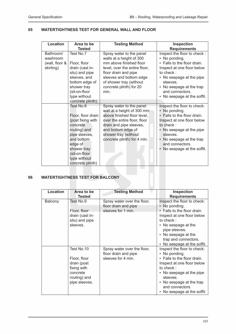
General Specification B8 – Roofing, Waterproofing and Leakage Repair
105
05 WATERTIGHTNESS TEST FOR GENERAL WALL AND FLOOR
Location Area to be Testing Method Inspection Tested Requirements Bathroom/ Test No.7 Spray water to the panel Inspect the floor to check : washroom walls at a height of 300 ▪ No ponding. (wall, floor & Floor, floor mm above finished floor ▪ Falls to the floor drain. skirting) drain (cast in- level, over the entire floor, Inspect at one floor below situ) and pipe floor drain and pipe to check : sleeves, and sleeves and bottom edge ▪ No seepage at the pipe bottom edge of of shower tray (without sleeves. shower tray concrete plinth) for 20 ▪ No seepage at the trap (sit-on-floor min. and connectors. type without ▪ No seepage at the soffit. concrete plinth). Test No.8 Spray water to the panel Inspect the floor to check: wall at a height of 300 mm ▪ No ponding. Floor, floor drain above finished floor level, ▪ Falls to the floor drain. (post fixing with over the entire floor, floor Inspect at one floor below concrete drain and pipe sleeves, to check : routing) and and bottom edge of ▪ No seepage at the pipe pipe sleeves, shower tray (without sleeves. and bottom concrete plinth) for 4 min. ▪ No seepage at the trap edge of and connectors. shower tray ▪ No seepage at the soffit. (sit-on-floor type without concrete plinth)
06 WATERTIGHTNESS TEST FOR BALCONY
Location Area to be Testing Method Inspection Tested Requirements Balcony Test No.9 Spray water over the floor, Inspect the floor to check: floor drain and pipe ▪ No ponding. Floor, floor sleeves for 1 min. ▪ Falls to the floor drain. drain (cast in- Inspect at one floor below situ) and pipe to check : sleeves. ▪ No seepage at the pipe sleeves. ▪ No seepage at the trap and connectors. ▪ No seepage at the soffit. Test No.10 Spray water over the floor, Inspect the floor to check: floor drain and pipe ▪ No ponding. Floor, floor sleeves for 4 min. ▪ Falls to the floor drain. drain (post Inspect at one floor below fixing with to check : concrete ▪ No seepage at the pipe routing) and sleeves. pipe sleeves. ▪ No seepage at the trap and connectors. ▪ No seepage at the soffit.

General Specification B8 – Roofing, Waterproofing and Leakage Repair
106
07 WATER TESTING FOLLOWING THE REPAIR OF WATER SEEPAGE TO WINDOWS
Location Area to be Testing Method Inspection Tested Requirements External Test No.11 Spray water evenly to the Inspect the window Windows three sides of the wall up surround on the internal Window to a height of 150 mm side of the window to surround and above the top of the check for any water junction of window opening and allow seepage. Ensure that no windows and to continue for a period of water has entered window 10 min. throughout the window openings from the junction with the surrounding window opening, to either side or sill to opening.
B8.5 CHEMICAL INjECTION / GROUTING
The repair materials shall be of a single or low number of components. The contractor shall submit evidence of previous track records, test reports and manufacturers’ recommendations in relation to his proposed repair materials for approval.
Adequate and proper precaution shall be taken to ensure that carrying out of the entire water seepage repair work is under strict procedural steps as recommended by the manufacturer. Proper protective clothing and device for eyes protection shall be used and the safety procedures as laid down by the Labour Department shall also be followed.
Repair of water leakage to external wall by chemical injection shall be in the following sequences and manners: -
(i) Identify the wet patches and potential infiltration areas; (ii) Submit a method statement for the sealing infiltration including surface preparation and
touching/painting finishes for approval prior to commencement of work; (iii) Clean the affected areas contaminated by deposits of dirt, dust, lime, salt or other
contaminants; (iv) Flush the affected area with water and/or brush with wire brush prior to chemical injection/
grouting; (v) Drill injection nipples at suitable intervals (say every 300mm max.) along the crack,
secured and cover the nipples and the crack between the pipes with epoxy putty; (vi) Inject approved materials into nipples by injection pump strictly in accordance with the
manufacturer’s recommendation; (vii) Upon completion of grouting/injection, remove the nipples and re-paint the repaired and
affected areas to match with existing.
The approved injection/grouting materials by Contract Administrator shall have the following properties: -
(i) A polyurethane resin or foam/gel chemical waterproofing grout or equivalent. (ii) Be capable to react with potable water and/or seawater to form a polyurethane foam to fill-
up cracks for waterproofing. (iii) Be capable to resist weathering, abrasion and chemicals (i.e. organic solvents, mild acids,
alkali and micro-organisms). (iv) The polyurethane resin should be able to penetrate the width of hairline crack/joint
of smaller than 0.5mm with high-pressure and width of greater than 0.5mm with low-pressure.
(v) It should have an approximate pH value between 3 to 12. (vi) It should be non-flammable. (vii) The resin should be of light colour transparent liquid and can be painted upon. (viii) Having a density of approximate 1 kg/litre. (ix) Insoluble in water. (x) Stable and good for storage in the original resealable container at room temperature for
one year.

General Specification B8 – Roofing, Waterproofing and Leakage Repair
107
(xi) Not be affected by freezing and thawing. (xii) High Flash Point at approximate 166oC. (xiii) Non-Toxic.
The approved injection/grouting materials shall have at least 5-year warranty.
B8.6 RETANKING WORKS FOR POTABLE WATER TANK
01 SUPPLY AND INSTALL TEMPORARY WATER SUPPLY
Water supply shall be provided to individual units including installation of new temporary water tanks, pump sets and pipeworks during the re-tanking works and shall be removed afterward. The licensed plumber shall submit the capacity of temporary water tanks and structural calculation for installation of the temporary water tanks for Contract Administrator’s approval.
The shop drawing of the temporary water supply pipe routing shall be prepared by licensed plumber in compliance with the current related Ordinance, Regulations and Code of Practice.
The suspension of fresh water shall be within 1 hour and shall not be overnight.
02 CAREFULLY REMOVE AND CART AWAY ALL TANKING FINISHES
Existing potable water tanks, including plaster & screed, waterproofing, sealant, wire mesh shall be removed to expose bare and sound concrete substrate. All debris and loose matters shall be cleaned off and surface shall be made good to receive new tanking finish. The Contractor shall also remove from the surface of the screed any contaminants such as grease, oil, moss and lichen, using two coats of fungicidal wash and rinsing with clean water.
03 SAW CUTTING AND HACKING OFF ALL EXISTING DEFECTIVE CONCRETE
All existing defective concrete (incl. spalling, honeycomb, void, etc.) with render, plaster, screed shall be saw-cut and hacked off down to the sound concrete substrate and exposing the reinforcement. Rust on reinforcement shall be removed, concrete surface shall be prepared and rectified from defective, honeycomb, void and spalled concrete to all internal wall and floor of the potable water tank. Contract Administrator approved proprietary repair mortar system shall be applied to areas of removed defective concrete. Repairs shall be carried out strictly in accordance with the manufacturer’s instructions and recommendations.
04 WATERPROOF SCREED
The Contractor shall supply and apply not less than 20mm thick 1:3 cement sand screed with Contract Administrator approved waterproofing admixture to entire wall and floor of potable water tank. The screed shall be laid to fall at not less than 1:100 and embedded with zinc coated hexagon steel wire mesh reinforcement with 19mm size to the floor. All cement sand screeding & plastering shall be mixed in accordance with the manufacturer’s instructions.
Flooding test shall be carried out by flooding the whole tank for not less than 24 hours. The Contractor shall invite the Contract Administrator for joint inspection for any leakage.
05 UPON PASSING THE FLOODING TEST
All temporary blockage to water outlets and dams shall be removed to drain the flooded area. The discharge of the flooding water shall be carried out in a controlled manner under close supervision by the contractor. Damage to pipe sleeves, pipe fittings and brackets due to sudden thrust of discharged water shall be avoided. No debris shall be drained into the drainage system.
After completion of re-tanking works for potable water tank, the contractor shall submit Infra-red Thermography Survey report(s) to ensure that no water leakage has happened.
General Specification B8 – Roofing, Waterproofing and Leakage Repair
108
The contractor shall carry out the re-tanking works by Certified Workers for working in Confined Space. New ceramic tiles in white colour shall be supplied and applied to the entire internal wall and floor of the potable tank. Angle fillet and other preparation shall be provided where necessary as directed by the Contract Administrator.
B8.7 WATERPROOFING WORKS TO FLOWER BED FOR DOMESTIC UNITS
01 CAREFULLY REMOVE AND CART AWAY
All plant, flower, soil and finishes of existing flower bed for domestic unit, including plaster & screed, waterproofing, sealant, wire mesh shall be removed to expose bare and sound concrete substrate. All debris and loose matters shall be cleaned off and surface shall be made good to receive new tanking finish. The Contractor shall also remove from the surface of the screed any contaminants such as grease, oil, moss and lichen, using two coats of fungicidal wash and rinse with clean water. All plant, flower and soil, etc. shall be protected and set aside for reinstatement.
02 SAW CUTTING AND HACKING OFF
All existing defective concrete (incl. spalling, honeycomb, void, etc.) with render, plaster, screed shall be saw-cut and hacked off down to the sound concrete substrate and exposing the reinforcement. Rust on reinforcement shall be removed, concrete surface shall be prepared and rectified from defective, honeycomb, void and spalled concrete to all internal wall and floor of the potable water tank. Contract Administrator approved proprietary repair mortar system shall be applied to areas of removed defective concrete. Repairs shall be carried out strictly in accordance with the manufacturer’s instructions and recommendations.
03 WATERPROOF RENDER
The Contractor shall supply and apply not less than 20mm thick 1:3 cement sand render with Contract Administrator approved waterproofing admixture to entire wall and floor of flower bed. The render shall be laid to fall at not less than 1:100 and embedded with zinc coated hexagon steel wire mesh reinforcement with 19mm size to the floor. All cement sand render shall be mixed in accordance with the manufacturer’s instructions.
Water test shall be carried out by flooding the whole flower bed for not less than 24 hours. The contractor shall invite the Contract Administrator for joint inspection for any leakage from the flower bed. Upon passing the flooding test, all temporary blockage to water outlets shall be removed to drain the flooded area. The discharge of the flooding water shall be carried out in a controlled manner under close supervision by the contractor. Damage to pipe sleeves, pipe fittings and brackets due to sudden thrust of discharged water shall be avoided. No debris shall be drained into the drainage system.
04 REFILL
Soil shall be refilled and flower and plant, etc. shall be replanted to the flower bed.

109
B9 FloorFinishes
General Specification B9 – Floor Finishes
110
B9 FLOOR FINISHES
B9.1 SCREEDS
B9.1.1 MATERIALS
01 GENERAL
Floor screeds generally shall be in accordance with CP 204:Pt. 2 and BS 8000:Pt 11.19.
02 MIXES FOR SCREEDS
Screeds generally shall consist of cement and sand 1:3. Minimum water consistent shall be used with workability. For floor screeds over 40 mm thick, mix shall be 1 part cement, 1.5 parts sand or granite fines and 3 parts coarse aggregate graded 10 mm down with at least 75% being retained on a 5 mm B.S. sieve. Granite fines instead of sand shall be used, when required to avoid efflorescence on the surface of the finish.
03 AGGREGATE FOR LIGHT-WEIGHT SCREEDS
Aggregate for lightweight screeds shall be as follows: (i) 5 mm exfoliated vermiculite to BS EN 13055-1:2002. (ii) Approved proprietary lightweight beads or granules.
04 AIR ENTRAINING AGENT FOR LIGHT-WEIGHT SCREEDS
Air entraining agent for lightweight screed shall be an approved admixture which will produce screeds with a dry density not more than 1,200 kg/m3.
05 VAPOUR BARRIER
Vapour barrier shall be 0.08 mm polythene sheet.
B9.1.2 WORKMANSHIP
01 PREPARATION FOR SCREEDS
Concrete surfaces shall be cleaned to remove dirt, dust, oil and other deleterious material. Neat cement slurry shall be brushed onto the existing surface immediately before applying the finish. A proprietary type of bonding agent approved by the Contract Administrator may be used instead of cement slurry.
02 THICKNESS OF FLOOR SCREEDS
Thickness of floor screeds shall be as follows: Type of Screeds Minimum Thickness (i) Laid monolithically with the base: 15 mm (ii) Bonded to a hardened concrete base: 20 mm (iii) Not bonded to the base: 50 mm including tile finish (iv) Floating: 65 mm including tile finish
03 LAYING FLOOR SCREEDS
Floor screeds which are to be laid monolithically with the base shall be applied in one coat within 3 hours after laying the base.
Screeds shall be laid between timber battens and in bays not exceeding 15 m2. The length of each bay shall not exceed 1½ times the width of the bay and the top surface of the batten shall be set to the required level.
General Specification B9 – Floor Finishes
111
Screeds shall be compacted to a uniform density throughout.
04 LIGHTWEIGHT SCREEDS
Lightweight aggregate screeds shall consist of cement and lightweight aggregate 1:8 for roofs and 1:6 for floors unless contrary to the manufacturers’ recommendations.
Air entrained screeds shall have a dry density of not more than 1,200 kg/m3. Lightweight screeds shall be 50 mm (minimum) thick, excluding topping.
Lightweight screeds shall be finished with cement and sand or granite fines 1:4 topping 15 mm (minimum) thick laid monolithically with the screed. When specified, vapour barrier shall be laid under lightweight roof screeds with lap 150 mm at joints.
05 SURFACE FINISHES FOR SCREEDS
The surface of screeds shall be finished with one of the following surface finishes, level, to falls as specified:
(i) a smooth untextured surface using a steel trowel or power float, (ii) an even textured surface using a wood float, or (iii) a slightly roughened texture using a stiff brush.
The finish shall be in accordance with manufacturer’s recommendations for the finish to be applied or laid.
B9.2 IN-SITU FLOOR FINISHES
B9.2.1 MATERIALS
01 STONE AGGREGATE
Stone aggregate shall be crushed grey granite or white stone to BS EN 12620:2002+A1:2008, graded from 10 to 3 mm and free from dust.
02 MARBLE AGGREGATE
Marble aggregate shall be angular crushed marble, free from dust, and of the colour required.
03 SURFACE HARDENER
Surface hardener shall be an approved proprietary liquid hardener and dust proofer.
04 HARDENING ADMIXTURE
Hardening admixture shall be an approved proprietary make.
05 DIVIDING STRIP
Dividing strip shall be aluminium, brass, stainless steel or plastic strip 3 mm thick and to the full depth of the screed.
Plastic strip shall be of the colour required.
Form key as one of the following: (i) Generally sides of section shall be grooved. (ii) Metal strip: one edge shall be cut and bent at 150 mm centres, to form lugs. (iii) Plastic strip: to have 5 to 10 mm holes at 150 mm centres with plastic pins inserted to
form dowels.

General Specification B9 – Floor Finishes
112
06 NON-SLIP STRIP
Non-slip strip insert shall be 25 x 15 mm slightly curved on top and consisting of: (i) A compound of cement and carborundum dust 1:1, or (ii) A proprietary insert strip.
B9.2.2 WORKMANSHIP
01 GENERAL In-situ floor finishes generally shall be in accordance with CP 204:Pt. 2. 02 CEMENT AND SAND FINISH
Finish shall be composed of cement and sand 1:3.
03 DIVIDING STRIP
Dividing strip shall be bedded through the total thickness of the base and finishing coat. Strips shall not be haunched prior to laying the base.
04 NON-SLIP STRIP
Non-slip compound shall be filled or bedded into groove, and finished to project 3mm above finished surface.
05 TERRAZZO
Terrazzo shall be applied in two coats and the minimum thickness of each coat shall be as follows:
Location First coat Finishing coat Floors 10 mm 15 mm Walls and dadoes 10 mm 10 mm Treads - 20 mm Risers - 15 mm
The first coat shall consist of cement and sand or granite fines in the proportions 1:3 by volume. The finishing coat shall consist of white or coloured cement and marble aggregate in the proportions 1:2½ by volume. The finishing coat shall be applied before the first coat has set.
Terrazzo shall be laid in bays not exceeding 12 m2. The length of each bay shall not exceed 1½ times the width of the bay. Bays shall be laid in a chequer board pattern and 24 hours shall be allowed between laying adjacent bays. Bays shall be separated from other bays and from adjacent finishes to the complete depth of both coats by 3 mm thick brass strips. Terrazzo shall be compacted to a uniform density throughout.
After curing has been completed for at least 7 days, the surface of terrazzo shall be ground to a smooth finish and to expose the aggregate. Voids in the surface shall be filled with matching cement.
One coat of wax polish shall be applied to the surface of wall finishes. Floor finishes shall not be highly polished or wax polished.
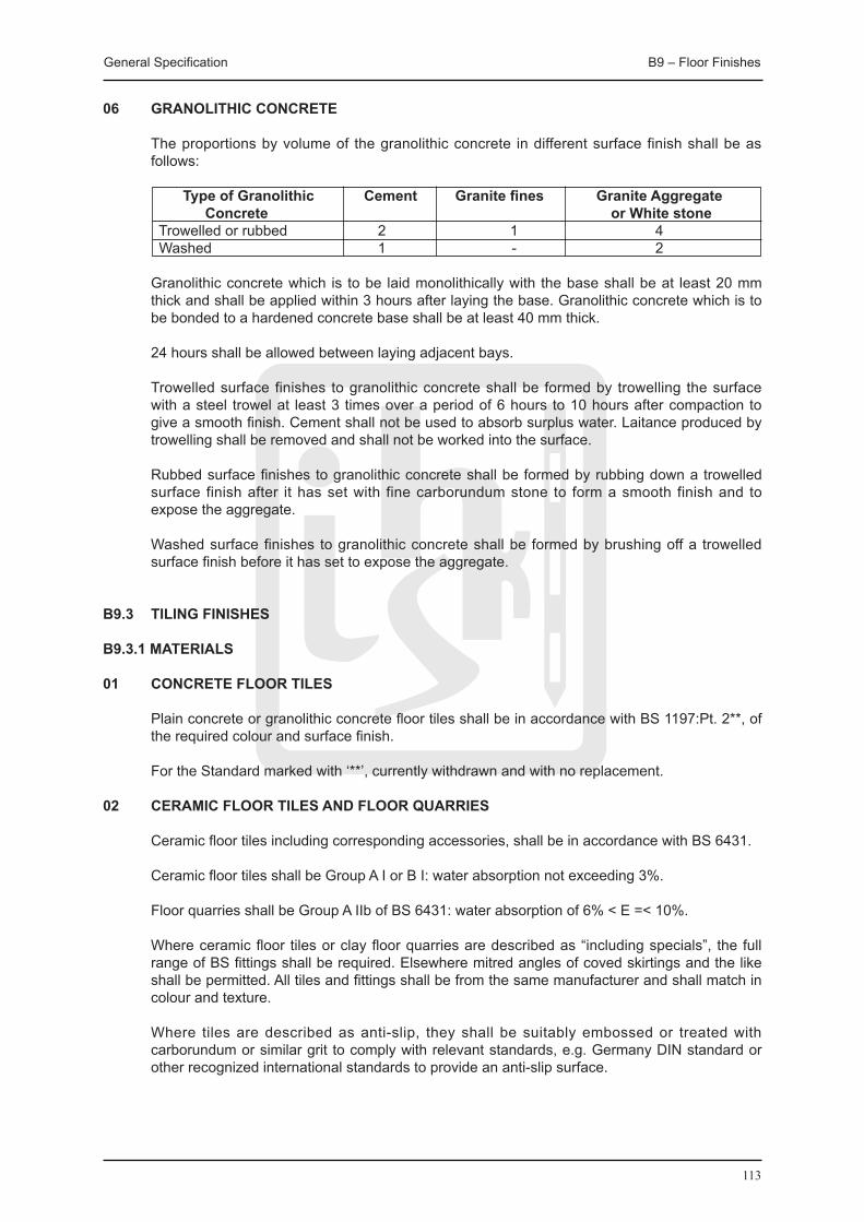
General Specification B9 – Floor Finishes
113
06 GRANOLITHIC CONCRETE
The proportions by volume of the granolithic concrete in different surface finish shall be as follows:
Type of Granolithic Cement Granite fines Granite Aggregate Concrete or White stone Trowelled or rubbed 2 1 4 Washed 1 - 2
Granolithic concrete which is to be laid monolithically with the base shall be at least 20 mm thick and shall be applied within 3 hours after laying the base. Granolithic concrete which is to be bonded to a hardened concrete base shall be at least 40 mm thick.
24 hours shall be allowed between laying adjacent bays.
Trowelled surface finishes to granolithic concrete shall be formed by trowelling the surface with a steel trowel at least 3 times over a period of 6 hours to 10 hours after compaction to give a smooth finish. Cement shall not be used to absorb surplus water. Laitance produced by trowelling shall be removed and shall not be worked into the surface.
Rubbed surface finishes to granolithic concrete shall be formed by rubbing down a trowelled surface finish after it has set with fine carborundum stone to form a smooth finish and to expose the aggregate.
Washed surface finishes to granolithic concrete shall be formed by brushing off a trowelled surface finish before it has set to expose the aggregate.
B9.3 TILING FINISHES
B9.3.1 MATERIALS
01 CONCRETE FLOOR TILES
Plain concrete or granolithic concrete floor tiles shall be in accordance with BS 1197:Pt. 2**, of the required colour and surface finish.
For the Standard marked with ‘**’, currently withdrawn and with no replacement.
02 CERAMIC FLOOR TILES AND FLOOR qUARRIES
Ceramic floor tiles including corresponding accessories, shall be in accordance with BS 6431.
Ceramic floor tiles shall be Group A I or B I: water absorption not exceeding 3%.
Floor quarries shall be Group A IIb of BS 6431: water absorption of 6% < E =< 10%.
Where ceramic floor tiles or clay floor quarries are described as “including specials”, the full range of BS fittings shall be required. Elsewhere mitred angles of coved skirtings and the like shall be permitted. All tiles and fittings shall be from the same manufacturer and shall match in colour and texture.
Where tiles are described as anti-slip, they shall be suitably embossed or treated with carborundum or similar grit to comply with relevant standards, e.g. Germany DIN standard or other recognized international standards to provide an anti-slip surface.

General Specification B9 – Floor Finishes
114
03 TERRAZZO FLOOR TILES
Terrazzo floor tiles shall be in accordance with BS EN 13748-2:2004, BS EN 13748-1:2004 and of the required colour and surface finish.
04 THERMOPLASTIC FLOOR TILES (PVC OR OTHERS)
Thermoplastic floor tiles shall comply with BS EN 649:1997 shall consist of a thoroughly blended composition of plastic binder, fillers and pigment. No asbestos fibres shall be present in the products, and shall have a minimum thickness of 2.5mm. Size shall be 225, 250 or 300mm squares.
05 ADHESIVE
Adhesive for tiles or mosaics shall be compatible with background and finish and shall be an approved proprietary brand. Adhesives for tiles shall comply BS EN 12004:2007. The approved proprietary adhesive shall be used in strict accordance with the manufacturer’s technical specifications and recommendations, including and not limited to the valid shelf life and the setting time of the product.
The expiry date and the setting time shall be clearly indicated with label and stamp for necessary inspection by the Contract Administrator.
06 SLURRY
Slurry shall be plain or coloured cement and water mixed to creamy consistency.
07 GROUT
Grouts mixed with plain or coloured cement shall be: (i) For floor tiling generally: cement and sand 1:3, mixed to a paste with minimum of water. (ii) For mosaic tiling or glazed wall tiling: cement and powdered limestone 1:3. (iii) For external facing tiles: cement and sand 1:3.
If agreed by the Contract Administrator, approved proprietary brands of grout may be used in strict accordance with the manufacturer’s technical specifications and recommendations.
B9.3.2 WORKMANSHIP
01 LAYING FLOOR TILES
Floor tiles shall be fixed as follows: (i) Using semi dry method direct to concrete base: (a) Soak tiles in clean water and allow to drain. (b) Lay semi-dry mix cement and sand 1:4 bed thoroughly compacted to the required
thickness (20 mm minimum) finished to the required levels, falls and currents. (c) Pour cement and sand slurry over bedding and spread and trowel to 3 mm (minimum)
thick. (d) Lay tiles, mixed from six boxes, and tamp firmly into bed with straight and even joints
and 3 mm (minimum) wide. (e) Allow bedding to set. (f) Grout up joints and clean surplus grout face of tiles as work proceeds. (ii) Using thick bed method to screed: (a) Soak tiles in clean water and allow to drain. (b) Damp the screed with clean water to reduce suction if required. (c) Lay cement and sand 1:3 bed generally 15 mm thick but never thicker than the tiles. (d) Coat back of tiles with slurry immediately before fixing. (e) Lay tiles mixed from six boxes and tamp firmly into bed with straight and even joints
and 3 mm (minimum) wide. (f) Allow bedding to set.
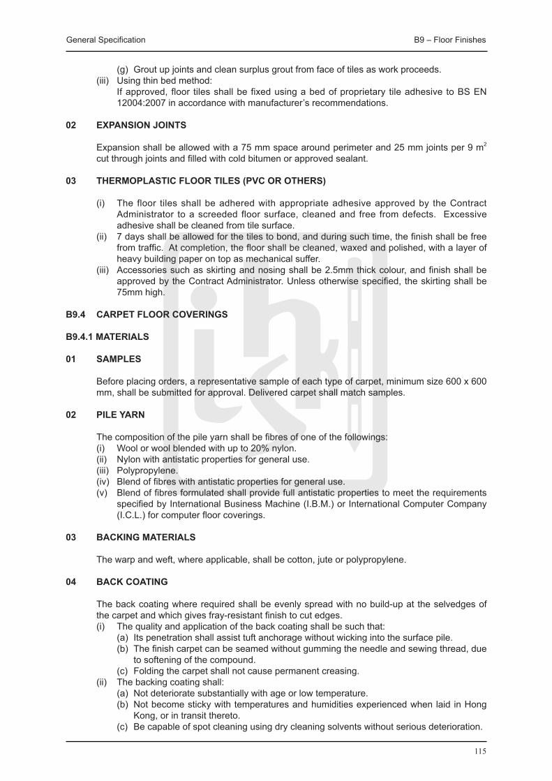
General Specification B9 – Floor Finishes
115
(g) Grout up joints and clean surplus grout from face of tiles as work proceeds. (iii) Using thin bed method: If approved, floor tiles shall be fixed using a bed of proprietary tile adhesive to BS EN
12004:2007 in accordance with manufacturer’s recommendations.
02 EXPANSION jOINTS
Expansion shall be allowed with a 75 mm space around perimeter and 25 mm joints per 9 m2 cut through joints and filled with cold bitumen or approved sealant.
03 THERMOPLASTIC FLOOR TILES (PVC OR OTHERS)
(i) The floor tiles shall be adhered with appropriate adhesive approved by the Contract Administrator to a screeded floor surface, cleaned and free from defects. Excessive adhesive shall be cleaned from tile surface.
(ii) 7 days shall be allowed for the tiles to bond, and during such time, the finish shall be free from traffic. At completion, the floor shall be cleaned, waxed and polished, with a layer of heavy building paper on top as mechanical suffer.
(iii) Accessories such as skirting and nosing shall be 2.5mm thick colour, and finish shall be approved by the Contract Administrator. Unless otherwise specified, the skirting shall be 75mm high.
B9.4 CARPET FLOOR COVERINGS
B9.4.1 MATERIALS
01 SAMPLES
Before placing orders, a representative sample of each type of carpet, minimum size 600 x 600 mm, shall be submitted for approval. Delivered carpet shall match samples.
02 PILE YARN
The composition of the pile yarn shall be fibres of one of the followings: (i) Wool or wool blended with up to 20% nylon. (ii) Nylon with antistatic properties for general use. (iii) Polypropylene. (iv) Blend of fibres with antistatic properties for general use. (v) Blend of fibres formulated shall provide full antistatic properties to meet the requirements
specified by International Business Machine (I.B.M.) or International Computer Company (I.C.L.) for computer floor coverings.
03 BACKING MATERIALS
The warp and weft, where applicable, shall be cotton, jute or polypropylene.
04 BACK COATING
The back coating where required shall be evenly spread with no build-up at the selvedges of the carpet and which gives fray-resistant finish to cut edges.
(i) The quality and application of the back coating shall be such that: (a) Its penetration shall assist tuft anchorage without wicking into the surface pile. (b) The finish carpet can be seamed without gumming the needle and sewing thread, due
to softening of the compound. (c) Folding the carpet shall not cause permanent creasing. (ii) The backing coating shall: (a) Not deteriorate substantially with age or low temperature. (b) Not become sticky with temperatures and humidities experienced when laid in Hong
Kong, or in transit thereto. (c) Be capable of spot cleaning using dry cleaning solvents without serious deterioration.
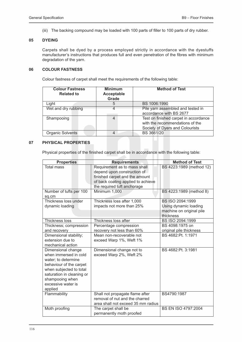
General Specification B9 – Floor Finishes
116
(iii) The backing compound may be loaded with 100 parts of filler to 100 parts of dry rubber.
05 DYEING
Carpets shall be dyed by a process employed strictly in accordance with the dyestuffs manufacturer’s instructions that produces full and even penetration of the fibres with minimum degradation of the yarn.
06 COLOUR FASTNESS
Colour fastness of carpet shall meet the requirements of the following table:
Colour Fastness Minimum Method of Test Related to Acceptable Grade Light 5 BS 1006:1990 Wet and dry rubbing 4 Pile yarn assembled and tested in accordance with BS 2677 Shampooing 4 Test on finished carpet in accordance with the recommendations of the Society of Dyers and Colourists Organic Solvents 4 BS 3661/20
07 PHYSICAL PROPERTIES
Physical properties of the finished carpet shall be in accordance with the following table:
Properties Requirements Method of Test Total mass Requirement as to mass shall BS 4223:1989 (method 12) depend upon construction of finished carpet and the amount of back coating applied to achieve the required tuft anchorage Number of tufts per 100 Minimum 1,000 BS 4223:1989 (method 8) sq.cm Thickness loss under Thickness loss after 1,000 BS ISO 2094:1999 dynamic loading impacts not more than 25% Using dynamic loading machine on original pile thickness Thickness loss Thickness loss after BS ISO 2094:1999 Thickness; compression Percentage compression BS 4098:1975 on and recovery recovery not less than 60% original pile thickness Dimensional stability; Mean non-recoverable not BS 4682:Pt. 1:1971 extension due to exceed Warp 1%, Weft 1% mechanical action Dimensional change Dimensional change not to BS 4682:Pt. 3:1981 when immersed in cold exceed Warp 2%, Weft 2% water; to determine behaviour of the carpet when subjected to total saturation in cleaning or shampooing when excessive water is applied Flammability Shall not propagate flame after BS4790:1987 removal of nut and the charred area shall not exceed 35 mm radius Moth proofing The carpet shall be BS EN ISO 4797:2004 permanently moth proofed
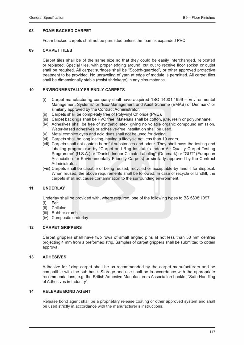
General Specification B9 – Floor Finishes
117
08 FOAM BACKED CARPET
Foam backed carpets shall not be permitted unless the foam is expanded PVC.
09 CARPET TILES
Carpet tiles shall be of the same size so that they could be easily interchanged, relocated or replaced. Special tiles, with proper edging around, cut out to receive floor socket or outlet shall be required. All carpet surfaces shall be “Scotch-guarded”, or other approved protective treatment to be provided. No unraveling of yarn at edge of module is permitted. All carpet tiles shall be dimensionally stable (resist shrinkage) in any circumstance.
10 ENVIRONMENTALLY FRIENDLY CARPETS
(i) Carpet manufacturing company shall have acquired “ISO 14001:1996 – Environmental Management Systems” or “Eco-Management and Audit Scheme (EMAS) of Denmark” or similarly approved by the Contract Administrator.
(ii) Carpets shall be completely free of Polyvinyl Chloride (PVC). (iii) Carpet backings shall be PVC free. Materials shall be cotton, jute, resin or polyurethane. (iv) Adhesives shall be free of synthetic latex, giving no volatile organic compound emission.
Water-based adhesives or adhesive-free installation shall be used. (v) Metal complex dyes and acid dyes shall not be used for dyeing. (vi) Carpets shall be long lasting, having a lifecycle not less than 10 years. (vii) Carpets shall not contain harmful substances and odour. They shall pass the testing and
labeling program run by “Carpet and Rug Institute’s Indoor Air Quality Carpet Testing Programme” (U.S.A.) or “Danish Indoor Climate Labeling” (Denmark) or “GUT” (European Association for Environmentally Friendly Carpets) or similarly approved by the Contract Administrator.
(viii) Carpets shall be capable of being reused, recycled or acceptable by landfill for disposal. When reused, the above requirements shall be followed. In case of recycle or landfill, the carpets shall not cause contamination to the surrounding environment.
11 UNDERLAY
Underlay shall be provided with, where required, one of the following types to BS 5808:1997 (i) Felt (ii) Cellular (iii) Rubber crumb (iv) Composite underlay
12 CARPET GRIPPERS
Carpet grippers shall have two rows of small angled pins at not less than 50 mm centres projecting 4 mm from a preformed strip. Samples of carpet grippers shall be submitted to obtain approval.
13 ADHESIVES
Adhesive for fixing carpet shall be as recommended by the carpet manufacturers and be compatible with the sub-base. Storage and use shall be in accordance with the appropriate recommendations, e.g. the British Adhesive Manufacturers Association booklet “Safe Handling of Adhesives in Industry”.
14 RELEASE BOND AGENT
Release bond agent shall be a proprietary release coating or other approved system and shall be used strictly in accordance with the manufacturer’s instructions.

General Specification B9 – Floor Finishes
118
B9.4.2 WORKMANSHIP
01 INSTALLATION
Installation of carpets and underlays shall be in accordance with BS 5325:2001.
Carpets shall be installed so that they are flat and of even tension. Carpet shall not be displaced by movement of people or objects on the surface to the point where permanent slackness, rucking or rippling is caused. Edges to skirting, cover fillets or other perimeters shall be closely fit. Carpet shall be joined at doorway within the thickness of the closed door.
Doorway terminations of carpet shall be secured by sealing, whipping or binding before seaming or covering with cover strips where they abut dissimilar materials.
No carpet jointing shall be permitted at right angles to a door location within 2 m of any door centre line unless accepted by the Contract Administrator. No fitting-out of areas with small pieces or offcuts shall be permitted.
02 LAYING UNDERLAYS
Underlays shall be provided in all cases except as follows: (i) Where foam or felt backing is an integral part of the carpet proposed. (ii) Where the carpet shall be fully adhered in accordance with the manufacturer’s
recommendations. (iii) Where the manufacturer recommends that no underlay is required. The base shall be
smooth, clean, and dry and compatible with the underlay and carpeting. Similarly any adhesive to be used shall be compatible with the base, underlay and carpet.
The underlay shall be smoothened by hand to ensure that it lies flat with no bubbles or wrinkles visible on the surface. The underlay shall be secured sufficiently to prevent movement when the carpet is laid over it.
03 SEAMING AND jOINTING CARPET
The layout of the carpet shall be planned to keep seams to the minimum practicable.
Seams shall be unobstructive and positioned such that, where possible: (i) They run the length of the area. (ii) Traffic runs along the length rather than across the seams. (iii) Seams shall not be placed in areas subjected to heavier or twisting wear or in doorways
or narrow accesses. Seam or joint carpet by one of the following methods: (a) Machine or hand sewing; sew seams to the full length and properly lock off. Stitch to
an even tension and ensure the seam lies flat after laying. Protect the raw edge of the pile where necessary, to prevent loss of pile along the seam.
(b) Reinforced tape and adhesive (cold applied); ensure that the adhesive is dry before stretching.
(c) Heat bonded tapes; ensure that adequate penetration of adhesive is achieved by applying sufficient heat and pressure simultaneously.
(d) Seaming cement; joint foam backed or unitary-backed carpets with a continuous bead of seaming cement to the full length of the primary backing and joint under compression.
04 INSTALLATIONS OF CARPET
Carpets shall be secured by using one of the following methods: (i) Carpet gripper method (suitable for woven, tufted, and secondary backed bonded carpet): Plug and screw or nail carpet gripper strip around the perimeter 6-8 mm from the skirting.
Use recommended adhesives between screws and nail centres. Stretch carpet over the gripper using knee kickers, trim the edge of the carpet and ensure that it is securely trapped in the gap between the gripper and the skirting. Use power stretchers for
General Specification B9 – Floor Finishes
119
installations over 7 m long or wide and use a double row of carpet grippers. (ii) Fully adhering method (suitable for all types of carpet): Ensure that the floor is properly dry, free from dust, and contaminants which will affect
the adhesion. Ensure that the adhesive is spread evenly and that only a sufficient area that can be properly bonded is laid at one time. Ensure that maximum adhesive contact is obtained by brushing or rolling in accordance with the manufacturer’s instructions.
Cut edges shall be seamed straight and square before adhesion in accordance with the manufacturer’s instructions. Trim the carpet to the perimeter before the adhesive dries.
Do not permit traffic or installation of furniture on adhered areas for at least 24 hours. (iii) Release bonded method (suitable for all types of carpet): Apply the release agent before adhering generally.
05 PROTECTION AND CLEANING
All carpet areas shall be cleared of tools and waste. All pieces of partly loose warp or face yarn shall be removed with napping scissors. All lumps, surface irregularities and areas of inadequate or uneven tension that are apparent shall be rectified.
The installed carpet shall be cleaned in an approved manner throughout the building once after completion prior to acceptance by the Contract Administrator.

120

121
B10 Woodwork

General Specification B10 – Woodwork
122
B10 WOODWORK
B10.1 MATERIALS
01 GENERAL Timber shall generally comply with BS EN 942:1996 and shall be of mature growth, properly
seasoned and sawn square. The timber shall be free from irregularities such as wood wasp holes, large loose or dead
knots, splits or other defects that will reduce its strength.
Pin holes and worm holes may be permitted in a slight extent in a small number of pieces, subject to the acceptance of the Contract Administrator, by examining the presence of active infestation of the materials, extent of impairment of the material and impact to the appearance of the finished faces of joinery work.
02 STORAGE
Timber shall be stored in a dry and well ventilated place and be protected from the weather. Timber shall be stacked properly to prevent distortion.
03 SOURCE IN PROGRESS TO CREDITABLE CERTIFICATION
Source in Progress to Creditable Certification shall refer to forest certification systems that assist to achieve FSC certification. Systems including WWF Global Forest and Trade Network (GFTN) Producer Groups, the Tropical Forest Trust, Smart Step, and SGS Malaysia (Certification Support Programme) are considered as sources in progress to creditable certification.
04 KNOWN LICENSED SOURCE
“Known Licensed Source” shall refer to the minimum acceptable status of a timber source. It refers to forest certification system (except FSC) that include a chain of custody system covering the timber being purchased (be aware that not all forest systems have this element). A list of acceptable forest certification system with a chain of custody system includes the followings:
(i) Programme for the Endorsement of Forest Certification Schemes (PEFC) – General (ii) PEFC – United Kingdom (iii) PEFC – Germany (iv) PEFC – Sweden (v) Canadian Standards Association (CSA) (vi) Cerflor (Brazil) (vii) Malaysian Timber Certification Council (MTCC)
05 SOFTWOOD
Softwood for carpentry shall be Pine, Cedar, Spruce or China fir or other species approved by the Contract Administrator. All timber shall be appropriately stamped or marked to identify origin and grade. All timber shall be kiln dried and vacuum impregnated to New Zealand Standard H3, or equivalent, with Copper Chrome Arsenate, or as directed otherwise by the Contract Administrator.
All softwood and softwood products shall be from a verifiable sustainable forest and shall be accredited with a certificate from the Forest Stewardship Council (FSC) or other Approved Authority. While a certificate from FSC is preferable, certificates, invoice copies and other paperwork from other systems that shows the product is either Known Licensed Source or Source in Progress to Creditable Certification are considered as acceptable certificates from Approved Authority.
General Specification B10 – Woodwork
123
06 HARDWOOD
Hardwood and hardwood products shall only be used in special circumstances under the direction of the Contract Administrator, and shall be certified as originating from a sustained resource or managed plantation as certified by the Forest Stewardship Council (FSC) or other Approved Authority.
While a certificate from FSC is preferable, certificates, invoice copies and other paperwork from other systems that shows the product is either Known Licensed Source or Source in Progress to Creditable Certification shall be considered as acceptable certificates from Approved Authority.
Density of hardwood shall be 720 kg/m3 (minimum) at 15% moisture content.
The following information shall be submitted to the Contract Administrator: (i) The species and country of origin. (ii) The name of the concessions or plantations from which these timbers originate. (iii) Copies of the forestry policies implemented by these concessions or plantations which
confirm that the management of the timber resource is sustainable. (iv) Shipping documents which confirm that the supplier in Hong Kong has obtained the timber
from the stated concessions or plantations. (v) Certificate from the Forest Stewardship Council (FSC) or other Approved Authority.
Hardwoods of unknown species or from unidentified sources are expressly prohibited.
07 TEAK
Teak, which is only permitted to be specified in special circumstances, shall have a density of 650 kg/m3 (minimum) at 15% moisture content. They shall be accredited with a certificate from the Forest Stewardship Council (FSC) or other Approved Authority.
08 FLOORING
Softwood or hardwood species used for timber flooring shall be obtained from a sustainable source as previously specified. Boarded or strip flooring shall be selected and approved hardwood, as specified, or as submitted to the Contract Administrator for selection. Finished thickness shall be 20 mm (minimum).
09 WOOD BLOCK FLOORING
Wood block flooring shall be approved high density resin bonded fibreboard flooring or other approved hardwood as specified. Finished thickness shall be 20 mm (minimum). Blocks shall be 300 mm x 50 mm in size and colour matched.
10 PARqUET FLOORING
Wood parquet flooring shall be obtained from a sustainable source as previously specified. Each block shall be 120 mm x 25 mm in size and 8 mm thick, and shall be tongued & grooved.
11 WEATHER BOARDING
Hardwood weather boarding shall be 150 mm wide and tapering from 25 mm to 10 mm thick and shall be:
(i) Sawn boarding or boarding wrot on one face and two edges with horizontal joints lapped 30 mm.
(ii) Boarding as (i) but with wider edge rebated with joints lapped 20 mm.
12 PLYWOOD Plywood shall comply with BS 1455:1972 and of the following grades, as specified: (i) “Grade 1 veneer” - hardwood faced, as specified, for natural finish.

General Specification B10 – Woodwork
124
(ii) "Grade 2 veneer" - luan faced for painting. Generally the bonding adhesive between veneers shall be resin adhesive classified as moisture
and weather resistant (M.R.) in BS 1203:2001. Nominal standard thicknesses of plywood shall be 3, 4, 5, 6, 9, 12, 15, 18 and 25 mm.
Plywood containing hardwoods of unknown species or from unidentified sources shall be expressly prohibited from use. Only plywood and plywood products made from softwoods or temperate hardwoods that originate from the Forest Stewardship Council (FSC) certified forests or other Approved Authority shall be used.
While a certificate from FSC is preferable, certificates, invoice copies and other paperwork from other systems that shows the product is either Known Licensed Source or Source in Progress to Creditable Certification are considered as acceptable certificates from Approved Authority.
13 MARINE PLYWOOD
Marine plywood shall comply with BS 1088:2003 bonded with Type W.B.P. adhesive between plys.
14 BLOCKBOARD
Blockboard shall be Grade 2 veneer for painting, and bonded with Type M.R. adhesive.
15 HARDBOARD
Hardboard shall comply with BS EN 316:1999, BS EN 321:2002, BS EN 322, BS EN 323:1993, BS EN 324-2:1993, BS EN 325:1993, BS EN 382-1:1993, BS EN 622-3:2004, BS EN 622-2:2004, BS EN 622-1:2003. “Standard” (Types SHA, SHB and SHC) or “tempered” (Type THE and THN) as specified.
16 INSULATING BOARD
Insulating board (Softboard) shall comply with BS EN 316:1999, BS EN 321:2002, BS EN 322, BS EN 323:1993, BS EN 324-2:1993, BS EN 325:1993, BS EN 382-1:1993, BS EN 622-3:2004, BS EN 622-2:2004, BS EN 622-1:2003.
17 WOOD CHIPBOARD
Wood chipboard shall be unsanded or sanded board complying with BS EN 1087-1:1995, BS EN 1128:1996, BS EN 120:1992, BS EN 309:2005, BS EN 310:1993, BS EN 311:2002, BS EN 312-1:1997, BS EN 312-2:1997, BS EN 312-3:1997, BS EN 312-4:1997, BS EN 312-6:1997, BS EN 317:1993, BS EN 319:1993, BS EN 322:1993, BS EN 323:1993, BS EN 324-1:1993, BS EN 324-2:1993, BS EN 325:1993, BS EN 326-1:1994, BS EN 633:1994, BS EN 634-1:1995.
Veneered chipboard shall be an approved proprietary brand. Melamine-faced chipboard shall comply with BS 7331:1990. All wood chipboards shall be low formaldehyde emission chipboard (Class E1) unless permitted otherwise by the Contract Administrator, or polyurethane - based chipboard with zero formaldehyde emission. Any boarding to be used in wet areas such as kitchens or bathrooms shall be High Moisture Resistant board complying with BS EN 316:1999, BS EN 321:2002, BS EN 322, BS EN 323:1993, BS EN 324-2:1993, BS EN 325:1993, BS EN 382-1:1993, BS EN 622-3:2004, BS EN 622-2:2004, BS EN 622-1:2003.
18 MEDIUM DENSITY FIBREBOARD (MDF)
Board type shall be moisture resistant grade (MDFMR) with density in excess of 600 kg/m3 complying with BS EN 316:1999, BS EN 321:2002, BS EN 322, BS EN 323:1993, BS EN 324-2:1993, BS EN 325:1993, BS EN 382-1:1993, BS EN 622-3:2004, BS EN 622-2:2004, BS EN 622-1:2003.

General Specification B10 – Woodwork
125
19 GLASS FIBRE
Glass fibre insulating quilt shall be light-weight bonded mat weighing 12 kg/m3 uncompressed.
20 SEMI-RIGID RESIN-BONDED GLASS FIBRE SLAB
Glass fibre insulating board shall be semi-rigid resin-bonded glass fibre weighing 45-48 kg/m3.
21 P.V.C. OR ACRYLIC SHEET
PVC or acrylic sheet shall be clear, translucent or coloured, as specified, and to be approved by the Contract Administrator.
22 LAMINATED PLASTIC SHEET
Laminated plastic sheet shall comply with BS EN 438:2005 Class HG (Horizontal-General Purpose) or VG (Vertical-General Purpose) as specified.
23 ACOUSTIC TILES
Acoustic tiles shall be of an approved proprietary brand meeting the requirements of BS EN 13964 manufactured from the following materials:
(i) Wood or other organic fibre insulating board complying with BS EN 316:1999, BS EN 321:2002, BS EN 322, BS EN 323:1993, BS EN 324-2:1993, BS EN 325:1993, BS EN 382-1:1993, BS EN 622-3:2004, BS EN 622-2:2004, BS EN 622-1:2003, 12 mm (minimum) thick for 300 mm x 300 mm tiles and 15 mm (minimum) thick for 400 mm x 400 mm tiles.
(ii) Mineral fibre or wool insulating board 12 mm (minimum) thick for 300 mm x 300 mm tiles and 15 mm (minimum) thick for 400 mm x 400 mm tiles.
(iii) Approved multi-purpose, dimensionally stable building board 6 mm (minimum) thick.
Tiles shall have a plain, perforated or fissured surface with a factory applied decorative finish. The edges shall be square, beveled, or beveled and grooved to suit the suspension system.
A certificate from the manufacturer confirming that the tiles are asbestos free shall be submitted to the Contract Administrator.
24 PROPRIETARY SUSPENDED CEILING SYSTEMS
The suspension ceiling system shall be an approved proprietary system meeting the requirements of BS EN 13964:2004+A1:2006 and the suspension system shall be manufactured from one of the following materials:
(i) Galvanized mild steel. (ii) Aluminium. (iii) A combination of galvanized mild steel and aluminium.
Aluminium sections shall be anodized where exposed. The panel grid shall be constructed of exposed tee or concealed ‘T’, ‘Z’ or other approved sections. Hangers shall be steel wires not less than 2 mm diameter, or straps, rods or combination of sections designed to facilitate the adjustment of grid levels, support the weight of the ceiling and all fittings and attachments.
Fixing to soffits shall be by means of approved sockets, anchors or other fixing devices cast into the slab or approved proprietary plugs or drill-anchors.
The system shall be so designed to facilitate the removal of at least 10% of the tiles without disturbing the remainder. Matching edge trim shall be provided to the perimeter of suspended ceilings. Samples of the panel grid complete with acoustic ceiling tiles shall be submitted for approval.

General Specification B10 – Woodwork
126
25 NAILS
Nails shall be steel nails complying with BS 1202:Pt. 1:2002, with “bright” finish, unless otherwise specified.
Nail lengths shall be not more than the total thickness of sections to be joined less 5 mm, or not less than twice the thickness of section through which nails are driven.
Where the thickness of the outer section through which nails are being driven is less than half that of the section to which nailing is being done, the depth of penetration of the nails into the latter shall be not less than 10 diameters of the nails being used.
26 SCREWS
Wood screws shall be brass, stainless steel, alloy or other non-corroding metal to BS 1210:1969 with countersunk heads, unless otherwise specified. Steel screws shall only be used for temporary work. The proper dedicated screws shall be used for all particle-board fixing.
Screw lengths shall be not more than the total thickness of sections to be joined, less 5 mm, or not less than one and a half times the thickness of section through which screws are driven.
Where the thickness of the outer section being screwed is less than half that of the section to which screwing is being done, the depth of penetration of the screwing into the latter shall be not less than the thickness of the outer section.
Screw cups shall be brass cups or stainless steel and comply with BS 1494:1969.
27 MASONRY NAILS
Masonry nails or drive pins shall not be used without approval of Contract Administrator.
28 EXPLOSIVE CARTRIDGE FIXINGS
Approval shall be obtained before using explosive cartridge operated fixings. All fixings shall be in accordance with the Factories and Industrial Undertakings (Cartridge-Operated fixing tools) Regulations. Tools, normally of the indirect acting type, plus pins and cartridges which correspond with the manufacturer’s specifications for that tool shall be used. A tool shall only be used by a person holding a certificate of competency specifying the maker and model of the tool on which he has been successfully trained.
29 PLUGS
Plugs for fixing to hard materials shall be proprietary plugs of plastic, soft metal, fibre or similar.
Fixing to friable materials, plasterboard and the like shall be proprietary fixings specially designed for that situation. The use of wood plugs shall not be permitted.
30 ADHESIVE
Adhesive for wood shall be as follows: (i) For internal use; synthetic resin adhesive classified as moisture resistant and moderately
weather-resistant (M.R.) in BS EN 301:2006, BS EN 302-1:2004, BS EN 302-2:2004, BS EN 302-3:2004, BS EN 302-4:2004.
(ii) For external use or internal use under very damp conditions synthetic resin adhesive classified as weather-proof and boil-proof (W.B.P.) in BS EN 301:2006, BS EN 302-1:2004, BS EN 302-2:2004, BS EN 302-3:2004, BS EN 302-4:2004.
Adhesive for fixing laminated plastic sheet shall be synthetic resin adhesive classified as weather-proof and boil-proof (W.B.P.) in BS EN 301:2006, BS EN 302-1:2004, BS EN 302-

General Specification B10 – Woodwork
127
2:2004, BS EN 302-3:2004, BS EN 302-4:2004.
Where the temperature exceeds 25 degree C, a “warm-setting” grade of adhesive shall be used. The use of animal glues shall not be permitted.
31 RESIN FOR MDF PANELS
All urea formaldehyde bonded MDF panels and MUF mouldings shall be manufactured with low emission resins conforming to European E1 emission standard of 9 mg/100 g (minimum).
32 WOOD PRESERVATIVE
Wood preservative shall be an approved proprietary brand exterior grade where completely concealed, or not decorated and colourless, coloured or suitable for overpainting where likely to be exposed or in contact with a painted finish.
33 MOSqUITO GAUZE
Mosquito gauze shall be one of the following: (i) Plastic covered glass fibre 7 x 7 mesh per 10 mm square. (ii) Copper wire 11 x 11 mesh per 10 mm square.
B10.2 WORKMANSHIP
01 GENERAL
Workmanship generally shall comply with BS 1186:Pt. 2:1988.
02 TIMBER
Timber shall be cut to required sizes and lengths as soon as practicable after the Works are begun, and shall be stored dry under cover so that the air can circulate freely around it.
Cut timber shall be stacked off a leveled, well-drained and maintained hard-standing ground and in such a manner as to prevent distortion.
03 DIMENSIONS
Dimensions of sections shown on the drawings shall be finished sizes. Planning and sanding faces to finished sizes shall be allowed.
Site dimensions shall be checked before prefabricating joinery fittings.
04 FRAMED jOINERY GENERALLY
Timber for joinery shall be planed on all faces. Exposed faces shall be finished to a fine glasspapered surfaces and round arrises to 1 mm radius.
05 FRAMED jOINTS
Faces of framed joints shall be square and shall be driven together to give a close, accurate fit. Joinery work shall be prepared and framed up with dry joints and stored until required for fixing. Before fixing open up all joints, the timber shall be put together with approved glue and wedge up. Any sections that have warped or developed shakes or other defects shall be replaced.
06 RUNNING BONDED jOINTS
Running bonded joints shall be cross-tongued, using approved tongues. For work over 40 mm thick, double tongues shall be used.
General Specification B10 – Woodwork
128
07 jOINERY WITH CLEAR FINISH
Joinery with clear finish shall be protected from damage or discolouration. Protection proposals shall be submitted to Contract Administrator for approval.
08 PROTOTYPES
Prototypes shall be prepared and submitted for approval for repetitive fittings before starting fabrication.
09 FIXING
Timber sections shall be plugged and screwed or secured to the backing by approved means. Location of buried services shall be checked before fixing to walls and other surfaces.
10 NAILING
Timber sections shall be nailed securely to the backing and it shall ensure that the nails do not split the timber. Split timbers shall be removed and replaced.
Nail heads shall be punched below timber surfaces visible in completed work.
Weather boarding shall be nailed to wood framing with not less than two corrosion proofed nails in the width of each board at each framing member.
11 SCREWING
When specified, timber sections shall be screwed to the backing including drilling pilot holes and countersinking heads flush with timber surfaces. Screws shall be inserted full depth with a screwdriver and not be hammered.
Countersink screw heads 5 mm (minimum) below timber surfaces shall be left with natural finish. Glue in colour and grain matched pellets cut from matching timber shall be used. Surface shall be finished off flush with face.
12 WOOD PRESERVATIVE
Wood preservative shall be applied to all unexposed surfaces of timber including framing fillets etc. and backs of frames, skirtings etc.
13 FIXING PLASTIC SHEET
Laminated plastic sheet shall not be fixed to timber with moisture content of more than 16%.
14 ACOUSTIC TILES
Acoustic tiles and the like shall be fixed to timber battens or directly to sub-base by means of an approved adhesive used in accordance with the manufacturer’s recommendations.
15 SUSPENDED CEILINGS
Suspended ceilings shall be constructed in accordance with BS EN 13964. Proprietary systems shall be fixed in accordance with the manufacturer’s recommendations. Ceiling tiles and grids shall be properly set out and that all cutting shall be done at the perimeter unless required to be otherwise in Particular Specification. All cover strips, edge trims and the like shall be fixed properly.
16 BOARDED OR STRIP FLOORING
Heading joints shall be cross-tongued, and staggered not less than two board widths apart.

General Specification B10 – Woodwork
129
Cramp flooring shall be tight and accurately fit along the whole length of the joint.
Flooring shall be fixed with galvanized, sheradised or cadmium-plated wire nails.
Nail square edged flooring shall not be faced more than 100 mm wide by using two nails. Nail heads shall be stopped and finished flush.
Tongued and grooved flooring shall be secret-nailed at each support with one nail placed just above the tongue and driven on skew. Nail heads shall be punched flush.
17 FIXING BATTENS
On concrete, 50 mm x 40 mm twice splayed fixing battens pre-treated with wood preservative shall be casted in or laid at 350 mm centres. Where laid on concrete bed, it shall be leveled in cement mortar (1:3), continuous support shall be provided for all batten lengths.
18 INFILLING BETWEEN
Space between battens shall be filled with lightweight concrete for drying out thoroughly.
One coat of approved bitumen/rubber latex emulsion at the rate of 1 litre/m2 shall be applied. Battens shall be checked and refixed after drying-out as may be required.
19 WOOD BLOCK FLOORING
The base shall be clean and dry. Wood blocks shall be fixed to screed with an approved cold bitumen/rubber emulsion adhesive and laid to herringbone or basket pattern, as specified, with straight border two blocks (minimum) wide. 5 mm expansion gap shall be provided at perimeter of areas of wood block flooring, and filled with one of the following:
(i) Cork strip (ii) Foam rubber strip
Surface of wood block flooring shall be sanded with an electric surfacing machine using sequentially graded abrasive paper to obtain a smooth surface ready to receive sealer or polish.
Machine shall be fitted with dust bag to control the release of dust.
20 PARqUET FLOORING
The base shall be clean and dry. Blocks shall be laid on one coat of an approved cold bitumen rubber emulsion adhesive applied to the screed with a serrated trowel. Flooring shall be left ready to receive sealer or polish.
21 DOOR & FRAMES GENERAL
Door frames shall not be used as formers for door opening construction unless with the permission of the Contract Administrator, and never when proprietary door sets are required in the Contract. In all such circumstances, templates or formers shall be used. The adoption of timber door sets may be accepted subject to the approval of Contract Administrator.
22 DOOR WITH BOARD FINISH
Hardwood ledged doors shall be constructed with 20 mm (minimum) vertical tongued and grooved boarding in about 150 mm widths. It shall be V-jointed on face side with ledges 5 mm thicker than boarding thickness and 100 mm wide for top ledge and 175 mm wide for middle and bottom ledges. Boarding shall be nailed to ledges and ends of ledges shall be screwed to boarding.
General Specification B10 – Woodwork
130
23 LEDGED AND BRACED
Hardwood ledged and braced doors shall be constructed with 100 mm wide diagonal braces of similar thickness to ledges. Braces shall be housed to ledges and ends shall be screwed to boarding.
24 FRAMED, LEDGED AND BRACED DOORS
Framed, ledged and braced doors of 45 mm (minimum) thickness shall be constructed with 115 mm wide stile and top rail, 225 mm wide middle and bottom rail, and 100 mm wide braces; and filled in with vertical boarding.
25 PANELLED DOORS
Hardwood paneled doors 40 mm (minimum) thick shall be constructed with 100 mm wide stiles, top rail and muntins and 200 mm wide middle and bottom rails.
Flat panels shall be 20 mm thick. Rebate shall be grooved or open framing shall be left, as specified, for panels or glass.
26 FLUSH DOORS
Stiles and rails generally shall be 75 mm wide. For doors exceeding 900 mm side or 2000 mm high stiles shall be 100 mm wide.
Infill for hollow core doors shall be 20 mm horizontal battens at 150 mm centres. Block out shall be provided for lock fixing, door closers, or other ironmongery as specified, or composition board core approved by the Contract Administrator.
Infill for solid core doors shall be 25 mm vertical battens tightly cramped together with the covering fully bonded both sides.
Both sides of the door shall be covered with the following as specified: (i) 3.2 mm standard hardboard (ii) 5 mm Plywood for painting (iii) 5 mm selected Hardwood faced plywood for clear finish (iv) Class HG laminated plastic bonded to 5 mm plywood (v) Other board finish accepted by the Contract Administrator.
12 mm selected hardwood lipping shall be provided, pinned and glued to all edges. Lipping to meeting edges of folding doors and meeting edges and heels of swinging doors shall be 25 mm thick, rebated or rounded. When specified, the bottom edge of doors shall be fitted with a 12 mm selected hardwood removable carpet strip screwed to the lipping.
27 CUPBOARD DOORS
Cupboard doors shall be constructed as follows, as specified: (i) Plywood or blockboard lipped on all edges with selected hardwood faced with laminated
plastic sheet or prepared for painting, or (ii) Hollow core doors (iii) Melamine Faced and lipped chipboard 28 OPENINGS IN FLUSH DOORS
Openings shall be framed with 12 mm (minimum) selected hardwood lipping. Lipping for glazing shall be rebated, if required.
General Specification B10 – Woodwork
131
29 GLAZING BEADS
Glazing beads shall be provided to match surrounding timber, be mitred at angles and fixed with screws and cups, where specified. Glazing beads shall not be less than 12 mm thick.
30 FIRE RESISTING TIMBER DOOR
Fire resisting timber doors shall be flush door as described above, including frames, hinges, door closers and any other hardware and shall comply with BS 476: Part 20-23.
Proprietary fire doors shall be tested in accordance with BS 476 and be subject to the approval of the Contract Administrator. Test report shall be provided to indicate that the material, product or construction is capable of resisting the action of fire for the specified period. The test shall be carried out and the test report shall be prepared by a laboratory recognized by the Hong Kong Laboratory Accreditation Scheme.
31 SMOKE AND INTUMESCENT SEALS
Folding or swing fire doors shall incorporate proprietary smoke seals and intumescent strips where necessary to attain the requirements of BS 476:Pt. 20-23.
32 ACOUSTIC DOORS
Acoustic doors shall be solid core doors with air-tight seals to all junctions with frames and threshold. Seal types shall be submitted to the Contract Administrator for approval unless specified in the Contract.
33 DOORS AND WINDOW FRAMES
Doors and window frames shall be constructed with properly framed joints and fixed using cramps or bolts and the bottom of door frames shall be secured with dowels.
34 BEDDING AND POINTING
Frames shall be bedded in cement mortar, leaving no gaps. For external doors, external face 10 mm deep shall be raked out, and pointed with an approved sealant.
35 ARCHITRAVES
Architraves shall be one length between angles and mitred at angle joints.
36 DRAWERS
Drawers shall be constructed with 20 mm thick front, as specified, 15 mm thick back and sides, as specified, dovetailed and framed together and 5 mm thick bottom housed on three sides. Drawers shall be set to slide on proprietary runners. Ironmongery shall be submitted for approval.

132

133
B11 Metalwork

General Specification B11 – Metalwork
134
B11 METALWORK
B11.1 MATERIALS
01 STEEL
Steel shall be hot-rolled or hot-finished steel complying with BS EN 10025:2005 or BS EN 10210:2006 respectively. All steel shall be Grade S275 or S355JR, except that hot-finished hollow sections shall be Grade S275J0H, S275J2H, S355J0H or S355J2H complying with BS EN 10210-1:2006.
02 GALVANIZED STEEL SHEET AND COIL
Hot dipped galvanized plain steel sheet and coil shall comply with BS EN 10143:2006.
03 STEEL MESH
Welded wire mesh shall be steel wire of the specified diameter welded to form a square or oblong mesh as specified and shall be hot dip galvanized after manufacture as specified.
Expanded steel mesh shall comply with BS 405:1987.
04 STEEL TUBING
Steel tubing shall comply with BS EN 10255:2004 “medium” grade and be galvanized.
05 SLOTTED STEEL ANGLE
Slotted steel angle shall be self-finished angle to BS 4345:1968. Fittings shall be cadmium plated steel.
06 CAST IRON
Cast iron shall be grey cast iron complying with BS 1561:1966 Grade 150.
07 ALUMINIUM ALLOY
Aluminium alloy plate; sheet and strip shall comply with BS EN 485:2008, BS EN 515:1993, BS EN 573 of required alloy designation.
Aluminium alloy bars, extruded tube sections and hollow sections shall comply with BS EN 573-3:2007, BS EN 755-6:2008, BS EN 755-3:2008, BS EN 755-4:2008, BS EN 755-2:2008, BS EN 755-8:2008, BS EN 755-7:2008, BS EN 12020-2:2001, BS EN 755-9:2008 alloy designation 6063.
Aluminium sections for structural purposes shall comply with BS 1161:1977
Aluminium alloy drawn tubes shall comply with BS EN 515:1993, BS EN 573 and BS EN 754:2008 alloy designation 6063.
08 BRASS RODS AND SECTIONS
Brass rods and sections shall comply with BS EN 12163:1998, BS EN 12164:1998, BS EN 12167:1998 designation CZ 106 condition M.
09 STAINLESS STEEL
Stainless steel plate, sheet and strip shall be of grade 316 or 304 complying with BS EN 10029:1991, BS EN ISO 9445:2006, BS EN 10048:1997, BS EN 10095:1999, BS EN 10051:1991+A1:1997, of Finish No. 2A for reflective finish, No. 2B for mill finish, No. 4 for
General Specification B11 – Metalwork
135
polish finish with fine grit and No. 8 for bright reflective mirror polished finish with a high degree of image clarity, or otherwise as required. Where welding is required, the steel shall be grade 316S13 or 304S11.
Stainless steel anchors and inserts shall be of grade 316S31, A4 complying with BS EN ISO 3506-1:1998, BS EN ISO 3506-2:1998.
10 FIXINGS
Fixings generally shall be of the same material and finish as the material to be fixed.
11 METAL INSERT CHANNELS FOR CONCRETE
Concrete insert channel shall be an approved galvanized steel channel, with expanded polystyrene temporary filler and provided with matching sliding fixing devices.
12 ADHESIVE FOR METAL
Adhesive for bonding metal to metal shall be an approved proprietary product complying with BS 5442: Part 3: 1979.
B11.2 WORKMANSHIP
01 FABRICATING
During fabrication, all surfaces that shall be visible in the finished work shall be protected.
Junctions of identical sections shall be mitred. Moving parts shall be assembled to move freely and without binding.
All burrs and sharp arrises which shall be visible after fixing or a hazard to the user shall be removed.
02 WELDING
Grease, dirt, moisture, oxide and scale shall be removed from the edges to be welded.
To ensure accuracy, clamps or jigs shall be used where practicable. Tack welds shall be used for temporary attachment where jigs are not practicable.
Joints shall be fully fused throughout with no holes, pores or cracks.
Weld splutter falling on self-finished surfaces visible in the completed work shall be prevented.
Butt welds, visible in completed work, shall be ground smooth and flush and fillet welds shall be ground smooth, if required.
Flux residue and slag shall be completely removed.
03 WELDING OF ALUMINIUM ALLOY
Welding of aluminium alloy shall be by inert-gas arc welding complying with BS EN 1011-4:2000 or other method subject to approval.
04 WELDING OF STAINLESS STEEL
Welding of stainless steel shall be by inert-gas arc welding complying with BS EN 1011-3:2000 or other method subject to approval.
General Specification B11 – Metalwork
136
05 BRAZING
Brazing shall comply with BS EN 14324:2004.
06 DESIGN OF ARTICLES TO BE COATED
Metal articles which are to be coated shall be designed in accordance with the recommendations of BS EN ISO 2081:2008, BS EN ISO 2082:2008.
07 FINISHING TO STEEL
Finishes to steel shall be as follows: (i) Bare to receive painted finish. (ii) Electroplated coating of zinc shall comply with BS EN ISO 2081:2008, BS EN ISO
2082:2008 Class A, 0.025 mm thick. (iii) Zinc sprayed coating shall comply with BS EN ISO 2063:2005 - nominal thickness 0.2 mm
unless otherwise specified. (iv) Galvanizing shall be hot-dip galvanizing complying with BS EN ISO 1461:2009 with a
minimum thickness of 85μm. Components shall be galvanized after fabrication, if required.
No zinc sprayed coated or hot-dip galvanized items shall be welded or drilled and any subsequent cutting is defined as damage which shall be subsequently made good after coating or galvanizing.
Damage to zinc coatings and galvanizing shall be made good, cut ends of galvanized sections shall be treated with two coats of metallic zinc-rich priming paint to BS 4652:1995 Type 2.
08 FINISHES TO ALUMINIUM Finishes to aluminium alloy shall be as follows: (i) Mill. (ii) Polished. (iii) Polished and treated with a protective lacquer. (iv) Clear anodized shall comply with AAMA 611 and of the thickness grade and surface
texture as follows: (v) Interior work Class 15 (minimum average thickness of 15μm). (vi) Exterior work Class 25 (minimum average thickness of 25μm). (vii) Internal concealed surface Class 10 (minimum average thickness of 10μm). (viii) Colour anodized shall comply with AAMA611 average 25μm thick. (ix) Approved proprietary hardcoat anodic finish with better wearing qualities than standard
anodizing of the required thickness.
09 CHROMIUM PLATING
Chromium plating shall comply with BS EN ISO 1456:2009, for “service condition No. 3”, with “bright”, “dull” or “satin” finish.
10 PROTECTION
All decorative finishes to metalwork shall be protected against damp, scratching and other damage. A strippable coating or masking tape shall be applied to all stainless steel, anodized aluminium or similar surfaces and shall only be removed as and when necessary for construction or just prior to inspection for handover. Surplus adhesive shall be removed with non-damaging solvent and be washed down.
11 CONTACT OF ALUMINIUM AND CONCRETE ETC.
Contact in the completed work between aluminium and concrete, mortar, plaster, or similar materials shall be avoided. Where unavoidable, one coat of bituminous paint shall be painted on aluminium surfaces, or approved tape shall be used.

General Specification B11 – Metalwork
137
12 CONTACT OF DISSIMILAR METALS
Contact in the completed work between the following metals shall be avoided: (i) Aluminium alloys with copper alloys, nickel, lead or stainless steel. (ii) Iron and steel with copper alloys. (iii) Zinc (including galvanizing) with copper alloys or nickel.
Where unavoidable, contact surfaces shall be coated with bituminous paint, protective tape or other approved means.
13 GALVANIZED STEEL TUBING
Galvanized steel tubing shall be carefully notched, fit and welded to produce accurate joints which shall be ground smooth and treated with two coats of zinc rich priming paint to BS 4652 Type 2.
14 CASTINGS
Castings shall be sound free from bubbles, cracks or other defects and shall include the construction of patterns and moulds as required.
15 SLOTTED STEEL ANGLE
Slotted steel angle shall be cut square and securely bolt together using nuts bolts and washers and angle braces as necessary.
16 FIXING STEEL MESH
Steel mesh shall be fixed at 75 mm centres as follows: (i) To steel framing by, (a) Tack welding. (b) Tying with 2 mm galvanized tying wire. (ii) To wood framing with 1.8 x 25 mm galvanized staples.
17 ON COMPLETION
Moving components shall be lubricated and adjusted, and left in perfect working order on completion.

138

139
B12 Windows
General Specification B12 – Windows
140
B12 WINDOWS
B12.1 GENERAL
Steel windows shall be obtained from an approved manufacturer and constructed to BS 6510:2005 and in accordance with the following:
(i) When fixed in position, windows shall be designed to withstand a wind load calculated in accordance with the Code of Practice on Wind Effects in Hong Kong with a minimum pressure of 3 kPa and a permissible maximum deflection of 1/180th of the length of the member under consideration. Calculations shall be submitted for approval.
(ii) Frames shall be square and flat with mitred, welded corners and with glazing bars machine tenoned and/or welded to frames.
(iii) Water bars shall be welded to the frames for the complete width of the windows. (iv) When weather bars are specified, they shall be welded to the frames for the complete
width of the windows. (v) All slotted adjustable lugs and screws necessary for building in the windows shall be
provided and lugs shall project 60 mm (minimum) beyond the metal frames. (vi) Loose mullions and transomes of total length to suit window openings together with
additional 75 mm at each end for building in shall be provided. (vii) Sufficient mastic and bolts for assembly of all composite units shall be provided and be
assembled at Site, including bedding mullions and transomes in mastic with all interstices completely filled.
(viii) Windows shall be suitable for external glazing unless otherwise specified. Windows shall be provided with rolled steel heavy channel section glazing beads size as specified, be mitred at corners and be fixed with galvanized mild steel flat headed countersunk screws at 225 mm centres (maximum) and frames shall be tapped to receive screws.
(ix) All members shall be hot-dip galvanized or zinc sprayed. (x) When specified, an approved chloroprene rubber or polyvinyl chloride weatherstrip
shall be provided and securely fixed into the dovetail groove in the section to provide a continuous contact between the opening casement and the fixed frame.
(xi) Window fittings and furniture shall be approved and as follows: (a) Steel hinges with brass pins and welded or riveted to frames. Projecting hinges to side-hung casements where windows shall be cleaned from the
inside. (b) All fittings including friction grip pivots, casement fasteners, spring catches, brackets,
slide arms, shoes, slip bolts, cabin hooks and eyes and handles, all of manganese brass with bronze finish. All to retain the opening parts rigidly in both the open and closed positions.
(c) Handle plates, round headed stay brackets welded to the fixed frames with interchangeable handles and stays.
(xii) Windows shall be hung to open as indicated and fitted with the following fittings and furniture:
(a) Side-hung casement and vertically centre-hung ventilator – a two-point nose fastener or a two throw casement fastener with mild steel adjustable connecting rod and a 250 mm peg stay or bronze sliding stay, as specified.
(b) Projecting casement - bronze sliding shoes, pivots and friction side arms and one spring catch with ring for hand or pole operation and two square-shank barrel bolts.
(c) Top-hung ventilator - 200 mm peg stay with round-headed stay bracket welded to the fixed frame and with a second peg to secure the stay firmly and horizontally against the first peg when the ventilator is closed.
(d) Bottom-hung ventilator - a spring catch and fanlight roller stay to limit opening and to permit the ventilator to swing free for cleaning.
(e) Horizontally centre-hung ventilator with a spring catch, with ring and eye for cord or pole operation.
(xiii) When specified, extruded aluminium flyscreens having plastic covered fibre-glass mosquito gauze with 7 x 7 mesh per 10 mm square shall be provided. Where flyscreens are provided, side hung casements shall have a locking handle and an opening and closing mechanism consisting of a bronze cam handle and bronze roto operator, and top hung casements to have bronze “through-the-frame” type stays.
(xiv) When specified, high openable windows in inaccessible locations shall be fitted with
General Specification B12 – Windows
141
remote control gear. (xv) Temporary steel clamps at the top and bottom of all opening lights of casements shall be
provided prior to transportation from factory till fixed in position.
B12.2 WORKMANSHIP
01 ALUMINIUM WINDOWS
Aluminium windows shall be obtained from an approved manufacturer and constructed in accordance with the following: -
(i) When fixed in position, windows shall be designed to withstand a wind load calculated in accordance with the Code of Practice on Wind Effects in Hong Kong with a minimum pressure of 3 kPa and a permissible maximum deflection of 1/180th of the length of the member under consideration. Where necessary galvanized steel cores, anchors, brackets, etc. shall be used as stiffeners. Calculations shall be submitted for approval.
(ii) Sections shall be extruded aluminium alloy to BS EN 485:2008, BS EN 515:1993, BS EN 573 and BS 1474:2008. British alloy designation 6063 with a minimum wall thickness of 2.0 mm and dovetail grooved for weatherstrip.
(iii) Frames shall be mechanically jointed of mortice and tenon construction to provide rigid and secure connections. Sash members shall be mechanically jointed and mitred to develop the full strength of members using solid block angle pieces and provide a neat weather-tight joint. Adequate drainage shall be provided in bottom members.
(iv) Galvanized steel fixing lug spaces at 300 mm centres (maximum) shall be provided for outer frames of each unit. Where specified, lugs shall be fixed with rag-bolts or approved proprietary stud anchors fixing bolts.
(v) Water bars of galvanized steel or other approved material shall be provided for the complete width of the windows where the design of the window requires.
(vi) All composite units, including provision of all necessary bolts, screws etc. shall be assembled at Site and all joints shall be sealed with an approved sealant.
(vii) Unless otherwise specified, an approved chloroprene rubber, polyvinyl chloride or nylon pile weatherstrip shall be securely fixed into the dovetailed groove in the window sections to provide a continuous contact between each opening part and its fixed frame.
(viii) Windows shall be suitable for internal glazing unless otherwise specified. An approved glazing system and aluminium beads shall be provided. Beads shall be securely clipped to the frame or beads which shall be an integral part of the frame shall be used.
(ix) Aluminium alloy, stainless steel or nylon shall be used for all exposed fixings including screws, nuts, bolts, washers and rivets and shall match up with finish where possible. Stainless steel, galvanized or cadmium-plated steel shall be used for all concealed fastening devices.
(x) Window fittings and furniture shall be approved and as follows: (a) Friction pivots and sliding stays - stainless steel. To provide a maximum opening of
100 degree and a minimum clearance of 100 mm between frame and window for cleaning purposes.
(b) Casement fasteners, locking handles, spring catches, casement stays, brackets, slip bolts and the like:
(1) diecast zinc alloy to BS EN 1774:1997 suitably coloured to match the anodised window or door metal.
(2) Moulded stainless steel with satin finish. (c) Locks cadmium plated steel with stainless steel or brass shoots etc. (d) Pull handles anodized aluminium. (e) Rollers, guides etc. cadmium plated steel with nylon or brass rollers to suit weight of
door or window. To be adjustable after installation. (xi) Remote control gear shall be hand operated shaft and lever or conduit and cable remote
control system with bronze or diecast zinc alloy bevel gear boxes, adjustable arms and keyed shafts.
(xii) Windows and doors shall be hung to open as indicated and fitted with the following fittings and furniture:
(a) Side and top hung windows - Friction pivots and sliding stays and casement fastener (dual if necessary) or pull handle and locking handle (dual if necessary). Top hung windows in inaccessible locations shall be fitted with remote control gear.
General Specification B12 – Windows
142
(b) Sliding windows - Rollers, guides etc., pull handle and stops, sliding bolts or locking mechanism. N.B. The window should be designed so that it cannot be lifted off its rollers without the removal of a safety device.
(xiii) When flyscreens are specified, they shall be located on the inside. The frames shall be extruded aluminium with plastic covered mosquito gauze of 7 x 7 mesh per 10 mm square. Screens shall be fixed to window frames by turn buckles. The windows shall be fitted with locking handles and an opening and closing mechanism comprising cam handles and rotor operator.
(xiv) All steel framework, cores, anchors and brackets shall be primed with zinc chromate primer and painted with two coats of bituminous paint.
(xv) Concealed aluminium or stainless steel surfaces which may come into contact with wet mortar, cement, plaster or similar materials shall be painted with one coat of bituminous paint.
(xvi) All exposed aluminium or stainless steel surfaces shall be applied with a strippable coating or masking tape. (NOTE: The anodised surface may be permanently damaged by contact with wet cement and plaster.) All window units and other associated materials shall be wrapped in stout waterproof paper or polythene to protect against damp and scratching and premature delivery to Site shall not be made.
(xvii) Windows shall be returned to site on completion of building work, the protective coating shall be removed carefully and be left clean.
02 FIXING METAL WINDOWS
When fixing metal windows: (i) Distortion during handling and storage shall be avoided. (ii) Tightness and clearance between sash and frame of all opening lights which shall be fixed
until glazed shall be ensured. (iii) Having construction access through window openings and/or placing scaffolding, boards
etc. directly onto the window frames shall be avoided. If window openings must be used, then window frames at that opening location shall not be fixed until after completion of the related internal works and the through-route is no longer required.
(iv) Composite units including the provision of all necessary bolts screws etc. shall be assembled and joints shall be sealed with an approved one pack gun type polysulphide sealant to BS EN ISO 11600:2003.
(v) Windows shall be positioned, plumbed, leveled and squared. (vi) Pockets shall be formed in heads, jambs, cills etc. to receive fixing lugs. Lugs shall be built
in and made good and screwed to frames or plugged and screwed frames using packing pieces where necessary. Frames shall not be distorted when tightening fixings.
(vii) Steel frames shall be bedded with water-proof mortar, leaving no gaps. Mortar shall be an approved ready-mix mortar or consist of 1 part of cement to 3 parts of sand together with the minimum amount of water necessary to achieve a consistency suitable for completely filling the gap between the frame and the opening. The mixture shall contain an approved proprietary water-proofing and non-shrink admixture.
(viii) Aluminium frames shall be bedded with water-proof mortar, leaving no gaps. Mortar shall be an approved ready-mix mortar or consist of 1 part of cement to 3 parts of sand together with the minimum amount of water necessary to achieve a consistency suitable for completely filling the gap between the frame and the opening. The mixture shall contain an approved proprietary water-proofing and non-shrink admixture.
(ix) Joints around external edge of steel window frames shall be raked out to the approval of the Contract Administrator and pointed with an approved oil based mastic sealant to form a smooth, flat joint. Excess sealant shall be removed from adjoining surfaces and left clean. Adjoining surfaces which would be impossible to clean shall be masked if smeared with sealant.
(x) Joints around external edge of aluminium window frames shall be raked out to the approval of the Contract Administrator and pointed with an approved one-pack gun type polysulphide sealant to BS EN ISO 11600:2003, sealant to form smooth, flat joint. Excess sealant shall be removed from adjoining surfaces and left clean. Adjoining surfaces which would be impossible to clean shall be masked if smeared with sealant.
(xi) Contact with concrete, mortar, plaster, or similar materials shall be avoided.
General Specification B12 – Windows
143
03 WINDOW SEALANT REPLACEMENT
The sequence of the removal of the existing sealant shall be started from the bottom, and then the two sides and finally the top portion.
The contractor shall pay extra attention to prevent any damage to the existing glass panel during sealant replacement works, and be responsible for any damage caused.
All window sealant replacement works as described in the contract shall include the following operations:
(i) Strip off and cart away all the existing mastic pointing around window frame on the external elevations.
(ii) Thoroughly clean the surface with brush or air jetting. (iii) If leakage is detected, hack off existing waterproof cement packing around the window
frame. Apply new packing with mosaic tile finish or material match to existing to replace the defective ones.
(iv) Place masking tape to both sides of joint to ensure a neat edge to the seal and protect substrate from removal of sealant is difficult. It should be applied before priming and be removed immediately after tooling, before the sealant starts to cures.
(v) To the sound waterproofing cement packing, re-caulk all the sealant to glass panels with approved mastic sealant at a width to depth ratio 2:1 to the joint between window frame and concrete. The contractor shall submit the test certificate and relevant information to the Contract Administrator for approval prior to work commencement.
(vi) All surfaces should be free from dust, oil, grease or other contamination. (vii) Tool the installed sealant with light pressure to spread the material against the back-up
material and the joint surface. (viii) Remove the masking tape and clean the surfaces.
The silicone sealant applied shall be approved by the Contract Administrator.
04 ROLLER SHUTTERS
Roller shutters shall be supplied and fixed in accordance with the following: (i) Steel roller shutters shall consist of horizontal hot dipped galvanized slats, which interlock
through their entire length to form a continuous hinge. The shutters shall be designed to withstand a wind load calculated in accordance with the Code of Practice on Wind Effects in Hong Kong with a minimum pressure of 3 kPa on the entire surface area of the shutter or otherwise specified.
(ii) Roller shutters shall be either: (a) Self-closing. (b) Manually operated by an endless chain. (c) Electrically operated. Self-closing shutters shall be operated manually through an internal self coiling
mechanism by lifting handles or a pole and hook. The mechanism shall be adjustable to control the effort required to raise or lower the door.
(iii) Shutters operated by means of an endless chain shall be fitted with a spur or worm reduction gear such that the shutter shall not fall or rise without manual operation of the chain.
(iv) Electrically operated shutters shall comply with the Code of Practice for Installation of Electrically Operated Sliding Gates, Sliding Glass Doors and Rolling Shutters published by the Electrical and Mechanical Services Department. The shutters shall be installed complete with electric motors, the associated overload protection, drive mechanism, limit switches, emergency stop, control buttons and other control devices required by the shutter manufacturer. The electrical installation of the shutter shall comply with the General Specification for Electrical Installation in Government Buildings of the Hong Kong Special Administrative Region, Architectural Services Department, and Code of Practice for the Electricity (Wiring) Regulations, Electrical and Mechanical Services Department.
(v) Shutters shall have a locking device, and in addition approved malleable iron shoot bolts shall be provided and fitted to the bottom bar at each end of all shutters to assist holding the shutter under high wind conditions.

General Specification B12 – Windows
144
(vi) The horizontal steel barrel carrying the shutter curtain shall be of suitable diameter and strength to resist deflection, be rust proofed and have adequate counter balance springs to ensure the correct balance of the shutter in all positions.
(vii) The shutter and its barrel shall be supported on brackets with adequate bearings. The brackets shall be provided with suitable fixings for attaching to the soffit, face or side of opening.
(viii) The vertical channel guides shall be of galvanised steel of adequate size and depth to hold the shutter curtain under high wind conditions and they shall be provided with adequate fixings for attaching to the soffit, face, jamb or side of openings or at base and apex in the case of movable mullions.
(ix) Hoods and casings shall be of galvanised steel of adequate gauge fully supported and braced to prevent any sagging or distortion. Access doors or plates shall be provided at the appropriate places to enable routine inspection and servicing to be carried out.
(x) Screws, bolts and fixing lugs shall be supplied as necessary for the assembling and fixing of the steel roller shutters.
(xi) All ungalvanised steel and cast iron shall be painted with one coat of rust inhibiting primer before despatch to Site.
(xii) Full details of motors, gearing, drive mechanism and control mechanism shall be provided and obtain approval. The motors, the associated control and protective devices shall be suitable for operating on local electricity supply. Totally enclosed three-phase induction motors are preferred. The motors, driving gears, limit switches, and control mechanism shall be accessible for inspection and servicing. An isolating switch shall be provided to isolate the electricity supply during inspection and servicing. Adequate electrical power supply shall be provided to the isolating switch.
(xiii) Auxiliary manually operated gear shall be provided. The changeover should be easily effected without climbing up to the gearing drive mechanism to engage the gears for manual operation or disengage the manual operating gear for electrical operation.
(xiv) An interlock switch shall be provided to prevent the locked roller shutters from operating electrically and shall be fitted on a stationary part (such as the guide rails) but not on the moving part of the roller shutters.
05 FIRE RESISTING SHUTTERS
The construction and installation of the fire resisting shutter shall comply with the requirements of the Code of Practice for Fire Resisting Construction, Building Authority. The activation devices shall be constructed according to the requirements of Fire Services Department. The operation of the fire shutter and the activation devices shall be tested according to the requirements of the Codes of Practice for Minimum Fire Services Installations and Equipment and Inspection, Testing and Maintenance of Installations and Equipment, Fire Services Department and the Building Services Branch Testing and Commissioning Procedure No. 3 for Fire Service Installation in Government Buildings, Architectural Services Department.
The fire rated period of the fire resisting shutters shall satisfy the criterion of integrity relating to the method of exposure on each side separately when tested in accordance with BS 476:parts 20 to 24.
A test report prepared by a laboratory accredited by the Hong Kong Laboratory Accreditation Scheme (HOKLAS) or Building Authority shall be provided to certify that the fire resisting shutter is capable of resisting the action of fire for the specified period.
The fire resisting shutters shall be provided with smoke detector(s) and manual control devise(s) on both side of the wall openings for automatic and manual operation respectively. The detectors installed shall comply with the requirements of the General Specification for Fire Service Installation in Government Buildings of the Hong Kong Special Administrative Region, Architectural Services Department.

145
B13 DoorsandIronmongery

General Specification B13 – Doors and Ironmongery
146
B13 DOORS AND IRONMONGERY
B13.1 GENERAL
Ironmongery shall be supplied in accordance with the Contract documents. All ironmongery shall be approved before orders are placed and shall be obtained from an approved manufacturer for that item and for the use intended.
Ironmongery shall be fixed carefully using fastenings with matching finish supplied by ironmongery manufacturer to prevent damage to ironmongery and adjacent surfaces.
Ironmongery shall be fitted and fixed in accordance with the manufacturer’s recommendations and instruction, where applicable, manufacturer’s fixing templates shall be used.
Exposed hardware shall have the finish specified and unless otherwise specified all hardware
on each item shall have identical or similar finish.
Screws shall match the finish of the article to be fixed and to be round, flat headed or countersunk as required and in accordance with BS 1494:1:1964.
One complete set of manufacturer’s fixing and maintenance instructions for the ironmongery shall be provided prior to delivery.
01 CERTIFICATION
Fully detailed catalogues, certificates of compliance or other documentary evidence from recognised testing laboratories accredited by UKAS or HKAS under the HOKLAS, or equivalent accreditation schemes, of the specified proprietary products shall be supplied to the satisfaction of the Contract Administrator that the ironmongery complies with the specified requirements.
02 CERTIFICATION FOR FIRE DOOR
All hardware for fire rated doors shall be compatible for certification of rating. Individual independent fire test/assessment certificates to BS EN 1634-1:2008 specific to each fire rated door assembly proposed for the works, shall be submitted to confirm compliance with required ratings.
03 DELIVERY, STORAGE AND HANDLING
Hardware shall be delivered to the job site in manufacturer’s original containers marked to correspond with the final hardware schedule for installation location and store in dry surroundings.
Secure lock-up shall be provided for hardware delivered to the project but not yet installed. Handling and installation of hardware items which are not immediately replaceable shall be controlled so that the completion of the work will not be delayed by hardware losses both before and after installation.
Hardware installation shall be coordinated with other work properly. Each item or package shall be tagged separately, with identification related to the final hardware schedule and include basic installation instructions in the package. Hardware items of proper design for use on doors and frames shall be provided with information such as thicknesses, profile, swing, security and similar requirements indicated as necessary for proper installation and function. Individually package hardware items shall be delivered at the proper times to the proper locations (shop or project site) for installation.
Each fabricator of doors, frames and other work shall be furnished with a copy of the final hardware schedule and all pertinent hardware templates or template information to be factory prepared for the installation of hardware. Upon request, the shop drawings of such other work shall be checked to confirm that adequate provisions are made for the proper installation of
General Specification B13 – Doors and Ironmongery
147
hardware.
04 PROTECTION
The contractor shall be responsible for protecting all ironmongery in those areas of work forming part of the contract. The contractor shall replace at his own expense broken or damaged ironmongery caused through lack of adequate protection or care in installation or handling.
The contractor shall make his own investigation to guard against local sources of attack and damage and take all necessary precautions for protection.
05 COMPLETION
Upon practical completion the contractor shall ensure that the following requirements are carried out:
(i) Remove all protective covering, clean all items of ironmongery and ensure that they are in proper working condition.
(ii) Properly arrange, identify, classify and tag any lock spanner wrenches, spare parts and any other tools furnished by the manufacturers with the ironmongery for handling over to the Contract Administrator.
(iii) Properly arrange in a file all guarantees and certificates, etc. of the manufacturers furnished with the ironmongery, if any, for handing over to the Contract Administrator.
B13.2 MATERIALS
01 MATERIALS
Materials as specified shall comply with the following standards:
Aluminium: BS EN 573-2:1995 alloy.
Stainless Steel: BS EN 10088-1:2005 Grade 316 (18/10/3 molybdenum bearing grade).
Lower grades will not be accepted for accessories such as lock strike plates, rebate components, etc.
Brass: BS EN 1652:1998 CZ121/2874 alloy.
Real Bronze: Solid cast bronze of suitable alloy.
02 FINISHES
Finishes as specified shall comply with the following standards:
Stainless Steel shall be to BS EN 10095:1999.
Electroplated coatings of nickel and chromium shall be to BS EN ISO 1456:2009.
Anodic oxidation coating on aluminium shall be to BS EN 12373-1:2001.
Electroplated coatings of cadmium and zinc on iron or steel shall be to BS EN ISO 2081:2008.
Phosphate treatment of iron and steel shall be to BS EN 12476:2000.
Finished surfaces of one material whether extruded, rolled, cast or stamped, shall match exactly in colour and texture and all finishes visible on a door face shall be visually identical, unless otherwise specified.
All concealed components including lock bodies shall be protected by the manufacturer’s
General Specification B13 – Doors and Ironmongery
148
standard finish which shall, where applicable, comply with the above standards.
Iron or steel surfaces shall be protected by galvanising to BS EN ISO 1461:2009, zinc or cadmium plating to BS EN ISO 2081:2008 and BS EN ISO 2082:2008 or other approved methods, to BS EN 1670:2007 corrosion resistance.
03 FIXINGS
Suitable, matching, metric, positive drive fixings (e.g. Allen key, ‘Supadriv’ or ‘Pozidriv’) of correct types and lengths shall be provided for background constructions, with visible finishes to match the item fixed.
04 HINGES AND PIVOTS
Hinges and pivots shall be to BS EN 1935:2002 of the appropriate class for the door size, weight and duty, with heavy-duty, maintenance free, concealed bearings.
Where door closers incorporating hold-open devices or a backcheck facility, hinges with a minimum Grade 12, 13 or 14 to BS EN 1935:2002 shall be used.
Hinges shall be stainless steel, all finished to match other hardware on the door face, including plating to match brass, bronze or other finishes, where required.
Hinges with nylon bearings shall not be permitted in fire-resisting door assemblies.
Hinges shall be countersunk drilled, fixed with matching screws and of the following types:
For timber doors and frames: Jig drilled, with staggered drilling pattern and 12SG x 32mm wood screws.
For pressed steel doors and frames: ANSI template drilled with M5 or M6 x 12.5mm machine threaded screws.
For timber doors with steel frames: Different drilling patterns for leaf and frame as appropriate to timber and metal substrate.
Outward opening external and/or security doors shall be provided with hinges with integral security studs.
Unless otherwise specified, two hinges shall be provided per leaf up to 1800mm high and one extra hinge for each additional 450mm height (or part thereof).
Conductor hinges or concealed fixing, flexible metal cable loops shall be provided to transfer wiring for electromagnetic fire hold closers, solenoid locks and the like between frame and door leaf.
05 OVERHEAD DOOR CLOSERS
Door closing devices shall be hydraulic controlled closing types, from matching suites, with a full range of optional functions, including adjustable power, adjustable backcheck, mechanical and electromagnetic stand open and delayed closing. Uncontrolled devices (e.g. spring hinges) are unacceptable, due to noise of operation and potential for damage to doors, frames, ironmongery, etc.
All door closing devices used on metal fire doors shall incorporate fire retardant fluid.
Overhead door closers shall be capable of being fitted on either hand of the door and shall close the door positively. Regulation of the closing and latching speed shall be undertaken by independent control valves.
General Specification B13 – Doors and Ironmongery
149
Closers for fire rated doors shall be tested to and comply with BS EN 1154 Category of Use 4, to close a door from up to 180 degrees. In accordance with the ABHM Code of Practice “Hardware for Timber Fire and Escape Doors” (Clause 3.3.1), Certifire Approved and CE Marked. No closer for use on a fire rated door shall be less than power Size 3.
All products shall have been incorporated in successful fire tests and assessed to BS 476:Pt. 22 (30, 60 and 120 minutes) and BS EN 1634 (30, 60 and 120 minutes).
In addition to the corrosion test requirements of BS EN 1154, which relate to performance only, the visual requirements for significant surfaces of BS EN 1670:2007, Clause 5.7 Class 3 shall apply.
Overhead surface closers shall suit doors of either hand and have 50mm maximum projection, plain, rectangular, solid bodies of aluminium, brass or stainless steel construction, with visible surfaces, including arms, finished identically to other items on the door and with no permanent visible markings (except as required by relevant standards).
Overhead surface closers, except to plant rooms and pipe ducts shall be equivalent to BS EN 1154 Class 4-8-2/4-1-1-3, power adjustable for doors from 400mm to 1100mm wide and 40kg to 80kg mass, or equivalent grade to Table 14.1 for doors of greater width/mass. They shall incorporate adjustable, hydraulic backcheck.
To avoid reductions in efficiency which may result when fixing surface mounted closers on the pull side of a door, test data for all closers specified with parallel (pull-to) or universal (push- or pull-to) arms shall be provided to show that the closer achieves the specified power classification(s) when mounted on the pull side of the door.
Where universal (push- or pull-to) arms are specified, the closers shall be fitted on the least visible face of the door.
Door mounted overhead concealed closers shall be equivalent to the BS EN 1154 Class 4-8-2/4-1-1-2, adjustable for doors from 500mm to 1100mm wide and 40kg to 80kg mass, or equivalent grades to Table 14.1 for doors of greater width/mass. The minimum door thickness shall be 45mm.
Transom mounted overhead concealed closers shall be to BS EN 1154 Class 4-8-4-1-1-3, for doors from 850mm to 1100mm and 80kg mass, or equivalent grades to Table 14.1 for doors of greater width/mass.
06 FLOOR SPRINGS
Floor mounted concealed closers shall be heavy duty, adjustable, hydraulic check types, with thermo-constant stabilising fluid. All floor springs shall be non-handed (i.e. they are reversible). Single action straps shall to be Grade 316 stainless steel, double action straps shall be forged steel, both with full intumescent protection.
All floor springs for double swing doors, including plate glass assemblies, shall have micro-adjustable toe-in and positive centering, to ensure that leaves can be fully aligned in closed position.
Single and double action floor springs shall be hydraulic check spring mechanisms sealed into an oil or hydraulic fluid box complete with a loose protected steel box for fixing within a concrete floor, a detachable cover plate with waterproof seal. Adjustment within the box shall provide full horizontal movement for door alignment, final positioning and height adjustment. The position of the floor spring within the loose box shall be adjustable after installation. The non-adjustable bottom strap shall be designed to suit the type, size and weight of the door but shall not be less than 160 mm long with holes for four screws. The top centre for double action floor springs shall be adjustable. If specified, a hydraulic back check shall be incorporated effective for the opening angle of the floor spring.
General Specification B13 – Doors and Ironmongery
150
On single action floor springs, the bottom strap and top centre shall be suitably offset to suit the frame details, projection of pull handles, adjoining wall layout and other aesthetic aspects.
Where floor springs are fitted to a fire door, the floor springs shall have been tested in conjunction with an appropriate fire door and passed the integral fire door test in accordance with BS 476:Pt. 22 or BS EN 1634.
In the event that the springs are fitted to metal doors, the specification shall be the same except that a non-ferrous strap shall be provided to suit the profile of the bottom rail of the door and the top centre shall suit the top rail of the door.
Exposed parts shall be finished to the same standard as the rest of the ironmongery unless stated otherwise in contract requirements. The top plate shall be satin finish stainless steel, 18/10/3 quality unless stated otherwise in contract requirements.
Floor springs for main circulation routes, auditorium and other heavy use locations shall be equivalent to BS EN 1154 Class 4-8-2/6-1-1-3, power adjustable for doors from 300mm to 1400mm wide and 20kg to 120kg mass, or equivalent grade to Table 14.1 for doors of greater width/mass. They shall incorporate adjustable, hydraulic or mechanical backcheck, built-in levelling device and complete with Grade 316 stainless steel covers.
Floor springs for other locations shall be equivalent to BS EN 1154 Class 4-8-1/4-1-1-3, adjustable power for doors up to 1100mm wide and 100kg mass, or equivalent grades to the following table for doors of greater width/mass. They shall incorporate hydraulic or mechanical backcheck, built-in levelling device and complete with Grade 316 stainless steel covers.
BS EN 1154: 1997
1 2 3 4 5 6 7 8 9
Door Recommended Test Closing moment Opening Door closer door leaf width door moment closer power mass between 0° between any between 0° efficiency size and 4° 88° other and 60° between
and 92° angle of 0° and 4° opening Nm Nm Nm max. Nm min. Nm max. % min. Nm max. kg min max. 1 <750 20 9 <13 3 2 26 50 2 850 40 13 <18 4 3 36 50 3 950 60 18 <26 6 4 47 55 4 1100 80 26 <37 9 6 62 60 5 1250 100 37 <54 12 8 83 65 6 1400 120 54 <87 18 11 134 65 7 1600 160 87 <140 29 18 215 65
NOTE 1: The door widths given are for standard installations. In the case of unusually high or heavy doors, windy or draughty conditions, or special installations, a larger power size of door closer should be used.
NOTE 2: The test door masses shown are only related to door closer power sizes for the purpose of the test procedure. These test door masses are not intended to indicate maximum values for actual use.
07 BARRIER FREE ACCESS
Door closing devices shall be designed to allow exterior and interior doors to be opened with forces of not more than 30N and 22N respectively. Closers for interior doors shall have a closing period of at least 3 seconds measured from an open position of 70 degrees to a point 75mm from the closed position measured from the leading edge of the door. Door closing devices include door closers and floor spring.
08 ELECTROMAGNETIC FIRE-HOLD CLOSERS
Electromagnetic fire-hold closers shall be to BS EN 1155 and of the same design, finish and standards as other closers. Surface type fire-hold closers and floor-mounted concealed type shall be equivalent to Class 3-5-4-1-1-3.
General Specification B13 – Doors and Ironmongery
151
They shall allow the door to: (i) Hold open electro-magnetically when set and, on receipt of a signal from a central fire
alarm or other device, automatically release and properly close. (ii) Close immediately if physically pushed to, if an integral fire officer test button is pressed,
or if power fails.
Power sources for fire hold closers shall be Class II Safety Isolated Transformers to BS EN 61558-2-6:1998 or IEC 61558-2-6:1997. If fire alarm systems do not incorporate clean contacts, transformers shall incorporate relay control interfaces.
09 AUTOMATIC DOOR OPERATORS
Automatic door operators shall be approved, high quality devices to BS 7036, to suit the door construction, configuration, location and frequency of use and operate at 230/240vAC 50Hz. Finishes shall match other hardware on the door and units shall be frame mounted wherever possible, on the door face least susceptible to weather and/or tampering.
Operators for fire rated doors shall be of suitable types which will not compromise the fire rating, linked to fire alarm systems to close automatically in case of fire.
Operators shall allow adjustment of opening and closing speed, hold open time, backcheck and power and allow manual override, in case of power failure.
10 DOOR SELECTORS
Where one leaf of a pair of self-closing doors must close before the other, due to rebated styles, latch bolts, suitable matching selectors to BS EN 1158 Class 3-5-*-1-1-3 (where “*” denotes the appropriate door mass from Table under Section 060), of types which do not obstruct ironmongery or affect fire ratings, shall be supplied. Use sprung-arm, under-frame fixing selectors for outward opening doors and gravity face fixing types for inward opening doors.
11 LOCKS Mortice lock suites shall be to BS EN 12209 with: (i) Forends and strike plates and rebate components if for rebated meeting edges, of
materials to match door furniture, with no exposed sharp edges or corners. (ii) Piercing for bolting through of single sided lever or knob furniture, if required. (iii) Facility for full reversal of handing, without opening the case. (iv) If to receive lever handles, special, heavy springing against progressive lever droop (levers
with sprung roses or back plates are unacceptable due to potential for damage and corrosion).
(v) If to receive knob handles, soft springing, with two-way action and 100mm minimum backset.
Cylinders shall be easily removable when the door is open, without dismantling trim but non-removable when closed.
Heavy duty, modular, security locks shall be obtained from a single reputable source with 60mm minimum backset and 72mm centres. Latch bolts shall be 11mm (minimum) low friction type, and deadbolts shall have 20mm (minimum) throw (except for privacy function lock) with griptight 8mm followers for noise reduction, closing efficiency, security and improved durability.
Heavy duty, high security locks and electrical solenoid locks shall have equivalent of 19mm (minimum) throw stainless steel, three part, low friction, guided latch bolts with anti-thrust devices and/or 25mm (minimum) throw deadbolts with hardened steel rollers, as appropriate. They shall be certified by approved security and fire rating body.
General duty locks shall have equivalent of 11mm (minimum) plated brass latch bolts and 13mm (minimum) plated brass deadbolts, with hardened steel rollers. WC cubicle locks shall be
General Specification B13 – Doors and Ironmongery
152
mortice type, with inside thumbturn and coin operated, outside emergency release. Emergency releases shall incorporate red/white outside indicators.
12 SECURITY LOCKS
Security locks shall be to BS 3621.
Security locks shall have minimum of five levers or, if pin or disc, mechanisms shall have a minimum of six pin or disc tumblers or more than one row of pins and rollers, such rows shall not be in the same plane.
Forends shall be of double thickness and each lock shall be capable of being fitted to fully rebated doors with 12.5mm or 25mm deep rebate by the addition of a rebating set.
Keys shall be registered in the name of the Government and duplicates only obtainable through the manufacturer. Prior to ordering, agree with the Contract Administrator the method of ordering, supplying and fixing to ensure the maintenance of security. Master keying shall not be permitted.
Exposed parts shall be satin finish stainless steel 18/10/3 quality. Rebating set shall be nickel plated brass to match.
13 BOLTS Bolts shall be to BS EN 12051 and of the following minimum classifications: (i) Flush bolts: Class 3-4-0-1-1-3-3, comprising keep and easy clean floor socket in wet
areas or dust-excluding floor socket in other areas. Bolts shall have a 9.5mm (minimum) diameter and shall be suitable to secure the inactive leaf of locking pair of doors.
(ii) Barrel, tower and mortice bolts: Class 3-4-0-1-1-3-3. (iii) Foot drop, square spring of garage door bolts and padlock bolts: Class 3-4-0-1-1-4-4.
Unless otherwise stated: (i) Bottom bolts shall be 150mm minimum long. (ii) Top bolts to doors up to 2000mm high shall be 150mm long. For taller doors, increase bolt length by 150mm for each 150mm of additional height, or part
thereof. For very tall doors, automatic flush bolts may be substituted. Bolts shall be of a high quality, lever action, flush type, with dovetail returns to resist forcing and/or frame damage. Mount lever action flush bolts to door edges, wherever practical, for concealed fixing.
Bolts to duct doors shall be of a good quality and anodised aluminium, surface type. Where doors open outwards, top bolts shall be necked to allow proper fixing.
14 DOOR STOPS
Door stops for the protection of doors, ironmongery or surfaces shall be of concealed fixing types with robust holders matching other ironmongery on the door and rubber inserts, which are easily replaceable.
15 SLIDING GEAR
Sliding gear shall be high quality, proprietary units of suitable type and capacity, to BS EN 1527.
16 DOOR VIEWER
Door viewers shall have viewing angle not less than 180 degrees.
17 INDICATING SIGN PLATES
Indicating sign plates shall be as for push plates, but satin anodized aluminium plates shall not
General Specification B13 – Doors and Ironmongery
153
be less than 1.6mm thick. Self-luminous exit signs to comply with BS 5499: Pt 2.
Fire safety signs, notices and graphic symbols shall be as for push plates, manufactured to the standards laid down in BS 5499:Pt. 1.
B13.3 WORKMANSHIP
Ironmongery shall be fitted and fixed in accordance with the manufacturer’s recommendations, where applicable, manufacturer’s fixing templates shall be used.
All morticing of doors and frames shall be carefully done to ensure that mortices are not oversize and that items are securely fitted, especially items morticed into half hour doors and frames where their fire-rated performance may be invalidated. Items morticed into one hour doors and frames must be protected by intumescent materials. For locks and latches, this protection shall comprise a layer of approved intumescent sheet on each side of the lock or latch case; any other morticed items shall be painted with intumescent paint before being fitted.
Screws shall be properly inserted to drilled pilot holes with a correctly sized screwdriver. Screws shall not be hammered even part of the way in.
Items when fixed where the screw head is burred shall have the screws replaced. Where required, screw or bolt threads shall be plugged to suit the construction to which the item is fixed.
Ironmongery shall be oiled and adjusted where required and left in perfect working order.
Door frames shall not be used as formers for door opening construction unless with the permission of the Contract Administrator, and never when proprietary door sets are required in the Contract. In all such circumstances, templates or formers shall be used. The adoption of timber doorsets may be accepted subject to the approval of Contract Administrator.

154

155
B14 InternalFittings and Furnishings
General Specification B14 – Internal Fittings and Furnishings
156
B14 INTERNAL FITTINGS AND FURNISHINGS
B14.1 PLASTERBOARD DRY LINING
B14.1.1 MATERIALS
01 NAILED DRY LINING Nails shall comply with BS 1202:Part 1:2002, galvanized steel wire with round flat heads and
fixing centres shall be 150 mm. 02 SCREW FIXED DRY LINING Screws shall comply with BS 1210:1969, zinc or cadmium plated with countersunk heads.
03 DRY LINING ON METAL FURRINGS Metal furrings shall be a type recommended for the purpose by board manufacturer, fabricated
from galvanized mild steel sheet, passivated and not less than 0.56 mm thick. Screws shall be zinc or cadmium plated self-drilling and tapping with countersunk heads.
B14.1.2 WORKMANSHIP
01 EXISTING FIXTURES, SERVICES, ETC Surface mounted pipework, conduit, cables, electrical outlets, fixtures, appliances, fixing
brackets, clips, skirtings, architraves, etc., shall be removed from existing backgrounds which are to be lined.
02 PREPARATION OF SOLID BACKGROUNDS All cutting, chasing, plugging and making good shall be completed. All loose material shall be removed by brushing thoroughly. All oil, grease, wallpaper, etc. shall be removed by scrubbing with water and detergent, washed
off and allowed to dry. Suction shall be adjusted as necessary using primers or bonding agents recommended for the
purpose.
03 TIMBER SUPPORTS Supports for wallboard shall ensure that additional noggings/battens, accurately positioned and
securely fixed, are provided where necessary to give full support to all edges of wallboards.
Supports for plank shall ensure that additional noggings, accurately positioned and securely fixed, are provided where necessary to give full support to edges of plank at perimeter of area being lined and to any cut/unbound edges.
04 ADDITIONAL NOGGINGS It shall ensure that noggings, bearers, etc., required to support fixtures, fittings and services are
accurately positioned and securely fixed. After fixing boards, positions of noggings, bearers, etc. shall be marked for following trades.
05 CONTROL SAMPLE
A representative area of dry lining in an approved location shall be completed for approval of
General Specification B14 – Internal Fittings and Furnishings
157
appearance before proceeding.
06 DRY LINING
Plasterboard: To BS EN 520:2004 with exposed surface shall be suitable to receive direct decoration.
Fixing, jointing and finishing materials and accessories, where not specified otherwise, shall be
as recommended by plasterboard manufacturer. Operatives shall be properly trained for dry lining work. Boards shall only be fixed in areas which have been made weathertight. Boards shall be cut neatly and accurately without damage to core or tearing of paper facing.
Cut edges shall be kept to a minimum and positioned at internal angles wherever possible and masked with bound edges of adjacent boards at external corners.
Boards shall be fixed securely and firmly to suitably prepared and accurately levelled
backgrounds. Heads of fastenings shall be set in a depression; do not break paper or gypsum core. Surface shall be finished neatly to give flush, smooth, flat surfaces free from bowing and abrupt changes of level. Damaged boards shall not be used.
07 CEILINGS
Boards shall be fixed to ceilings before walls and partitions. Boards shall be fixed with bound edges at right angles to supports and with ends staggered in adjacent rows.
08 INSULATION BACKED WALLBOARD
Damage to insulation shall be avoided and insulation shall not be cut away to accommodate services. Insulation or plasterboard shall be cut back carefully as appropriate along edges of boards at angles to give a continuous plasterboard face, with no gaps in the insulation.
09 jOINTS
Joints between tapered edges of boards shall be lightly butted. A 3 mm gap shall be left where cut/unbound edges occur.
A 3 mm gap shall be left between square edged boards which are to be finished with textured plastic compound.
10 VERTICAL jOINTS
Joints between boards on opposite sides of stud partitions shall be staggered and centred on studs.
Joints in two layer boarding shall be staggered between layers.
11 HORIZONTAL jOINTS
Horizontal joints shall not be permitted in wall lining.
Horizontal joints shall not be permitted in wall lining except where height of wall exceeds maximum available length of board. Positions of joints shall be agreed where not specified.
Two layer boarding, where permitted, shall be offset by at least 600 mm. Noggings shall be positioned to support horizontal joints in outer layer of boarding.

General Specification B14 – Internal Fittings and Furnishings
158
12 NAIL / SCREW FIXING TO TIMBER SUPPORTS
Nail / screw shall be fixed to all supports working from the centre of each board. Fastenings shall be positioned not less than 10 mm from bound and 13 mm from cut/unbound edges. Heads shall be set in a depression; no paper or gypsum core shall be broken.
13 FIXING WITH METAL FURRINGS
Furrings shall be set out vertically, at specified centres and adjacent to angles and openings. 200 mm long dabs of adhesive shall be bedded in at 450 mm centres. Short lengths of furring shall be bedded horizontally to provide continuous support to top and bottom edges of boards. All furrings shall be aligned accurately to a true, vertical plane, ensuring that specified cavity width is achieved.
Working from the centre of each board, screw to all furrings shall be fixed at not more than
300 mm centres and not less than 10 mm from the edge of the board. Heads shall be set in a depression; no paper of gypsum core shall be broken.
14 PAD AND DAB FIXING
Pads shall be set out in straight, horizontal lines, 100 mm above the floor, 230 mm below the ceiling and at not more than 1070 mm centres between. Pads shall be positioned to bridge joints between boards, on centre line of boards and adjacent to angles and openings.
Pads shall be bonded securely, adjusting thickness of bedding to ensure accurate alignment in
a true vertical plane. Thickness of bedding shall not be less than 3 mm. Trowel length dabs shall be applied to background, standing proud of pads, with 50-75 mm
gaps between, in lines around the perimeter of each board and also down the centre of each board.
Boards shall be pressed firmly against pads and temporarily secure to each pad with a double-
headed nail. Nails shall be removed after dabs have set.
15 ADHESIVE FIXING OF INSULATION BACKED WALLBOARD
Adhesive shall be spread evenly on background in 200 mm wide bands around the perimeter and down the centre of each board.
Each board shall be firmly tamped into position and secured with nine nailable plugs per board
evenly spaced in three rows, one row 50 mm from each edge and one in the centre. Heads shall be set in a depression; no paper or gypsum core shall be broken.
16 TAPED SEAMLESS FINISH
Edges of boards shall be lightly sand cut to remove paper burrs. VAC sealer shall be applied to exposed cut edges of boards and any other plaster surfaces to which tape is to be applied.
All joints and gaps shall be filled and covered with continuous lengths of tape, fully bedded.
When set, joints and gaps shall be covered with joint finish, feathered out to give a flush, smooth, seamless surface. Two coats of joint finish shall be applied at external angles.
Nail/screw depressions shall be spotted with joint filler to give a flush surface. Minor indents shall be filled and after joint, angle and spotting treatments have dried, surface
finish shall be applied to give a continuous consistent texture to surface of boards. 17 MINOR DAMAGE IN EXISTING PLASTERBOARD Where not specified otherwise, small areas of broken board shall be repaired by cutting away
General Specification B14 – Internal Fittings and Furnishings
159
the paper, removing loose core material and filling with joint filler. PVAC sealer shall be applied to exposed plaster and cut edge of paper before filling. Surface shall be finished off to give a flush, smooth surface ready for redecoration.
B14.2 TIMBER BOARD FLOORING / SARKING / LININGS / CASINGS
B14.2.1 MATERIALS
01 TIMBER BOARD FLOORING
Tongued and grooved softwood shall comply with BS 1297:1987. Boards shall comply with BS 1297:1987 except that blue stain, fissures, knot holes and loose
or unsound knots will not be permitted on the face side of flooring. 02 BATTENED TIMBER BOARD FLOATING FLOOR
Boards: Tongued and grooved softwood shall comply with BS 1297:1987. Moisture content at time of fixing shall not exceeding 19%. 03 TIMBER BOARD SARKING:
Boards shall be tongued and grooved softwood boards to BS 1297:1987. Moisture content at time of fixing shall not be more than 22%. Sarking shall be terminated at roof edges and junctions in accordance with drawings and
specification for slating/tiling work and as agreed by the slating/tiling contractor.
B14.2.2 WORKMANSHIP
01 GENERAL
Boards shall be kept dry and shall not be fixed to timber supports which have a moisture content greater than 18%.
Boards shall not be fixed internally until the building is weathertight. Boards shall be protected from dirt, stains and damage until Practical Completion.
02 MOISTURE CONTENT OF BASE
The following shall be ensured where floating floors are to be laid on a new concrete or screed base:
(i) Ensure that drying aids have been turned off for not less than 4 days, then test for
moisture content using an accurately calibrated hygrometer in accordance with BS 8201. (ii) Take readings in all corners, along edges, and at various points over the area being
tested. (iii) Do not lay flooring until all readings show 75% relative humidity or less.
03 MOISTURE CONTENT OF TIMBER
During delivery, storage, fixing and thereafter to Practical Completion, conditions of temperature and humidity shall be maintained to suit specified moisture content(s). When instructed by the Contract Administrator, timber shall be tested with an approved moisture meter to manufacturer’s recommendations.
General Specification B14 – Internal Fittings and Furnishings
160
04 VAPOUR CHECK MEMBRANE
Vapour check membrane shall be fixed carefully and neatly with taped joints to provide a fully sealed barrier free from tears and punctures.
05 TREATED TIMBER
Surfaces exposed shall be treated by minor cutting and drilling with two flood coats of a solution recommended for the purpose by main treatment solution manufacturer.
06 ACCESS PANELS
Size and position shall be agreed with Contract Administrator before boards are fixed. Additional noggings, battens, etc. shall be provided as necessary.
07 FIXING BOARDS
Each board shall be fixed securely to each support to give flat, true surfaces free from undulations, lipping, splits and protruding fastenings.
Movement of timber shall be allowed when positioning boards and fastenings to prevent
cupping, springing, excessive opening of joints or other defects. Heading joints shall be tightly butted and positioned centrally over supports, not less than two
board widths apart on any one support. All exposed nail heads shall be punched neatly below surface and any proud edges shall be
planed off.
B14.3 SUSPENDED CEILINGS
B14.3.1 MATERIALS
01 SUSPENDED CEILING(S)
Fire resistance of complete ceiling assembly shall comply with BS 476:Part 21, 22 and/or 23 as relevant.
Suspension system shall include all hangers, fixings, main runners, cross members, primary
channels, perimeter trims, splines, noggings, clips, bracing, bridging, etc., which are necessary to complete the installation and achieve the performance specified.
B14.3.2 WORKMANSHIP
01 GENERAL
When not specified otherwise, the relevant recommendations and performance requirements of BS 8290 shall be complied with for the selection and assembly of components and materials.
02 CONTROL SAMPLE(S)
Area(s) of the finished work shall be completed in approved location(s) as follows, and approval of appearance shall be obtained before proceeding.
03 ENVIRONMENTAL CONDITIONS
Areas for storage and installation shall be clean, dry, well ventilated and free from excessive and/or rapid variations of temperature and humidity.
No membrane material shall be installed until the building is weathertight and wet trades have
General Specification B14 – Internal Fittings and Furnishings
161
finished their work. Before, during and after installing, temperature and humidity shall be maintained at levels similar to those which will prevail after building is occupied.
Notwithstanding the above, delivery of materials and installation of the suspended ceiling will
be taken as acceptance by contractor of the suitability of the environmental conditions.
04 CONDITIONING Before fixing, material shall be stored on site for at least 48 hours in conditions similar to those
which will prevail after the building is occupied. Free circulation of air to all surfaces shall be maintained.
05 COORDINATION WITH OTHERS
Contractors shall ensure that:
(i) Related work within the void (services, partitions, fire barriers, fire stopping, painting, etc.) is at a suitable stage of completion to enable ceiling installation to proceed without damage or disfigurement to the ceiling system.
(ii) Fixtures around which the ceiling is to be installed are completed and that services, fire barriers, etc. are in the correct position relative to the ceiling grid.
(iii) Hangers do not press against services, etc. and are installed vertically. However, where obstructions prevent vertical installation ensure that hangers are braced against lateral movement or provide rigid bridging structures across obstructions.
(iv) Services integrated within the ceiling membrane are positioned accurately, supported adequately and aligned and levelled in relation to the membrane and suspension system.
06 INSTALLATION
Suspended ceiling materials and accessories shall be handled, stored and fixed in accordance with manufacturers’ recommendations and BS EN 13964:2004+A1:2006, ensuring compliance with design and performance requirements.
System shall be set out accurately to give level soffits free from undulations, lipping and
distortions in grid members. System shall be fixed securely with additional bracing and stiffening as necessary at upstands,
access hatches, partition heads, etc. to give a stable system resistant to wind induced uplift and other specified design loads and pressures.
Cartridge or powder activated methods shall not be used for top fixings or rivets for bottom
fixings of hangers.
07 PROTECTION
No part of the suspension system shall be subjected to loads for which it is not designed, including lateral loads from ladders, tower scaffolds, etc.
Membrane materials shall be handled carefully, kept clean, removed and replaced correctly
using methods recommended by the manufacturer, including clean gloves, tools, etc. as appropriate.
08 SETTING OUT
Unless shown otherwise, the ceiling shall be set out as follows: (i) Edge tiles/sheets shall never less than half in width or length. Grid shall be positioned to
suit board/tile size(s), allowing for permitted deviations from nominal size(s). (ii) All lines and joints shall be straight and parallel to walls unless specified otherwise. (iii) Instruction on setting out shall be obtained where surrounding walls or other building
elements and features to which the suspended ceilings relate are not square, straight or
General Specification B14 – Internal Fittings and Furnishings
162
level.
09 COMPLIANCE WITH LABORATORY TEST INSTALLATIONS
All materials, components, assembly procedures and details for the ceiling system shall be in accordance with accredited laboratory test reports.
Contract Administrator shall be provided with a copy of the relevant test installation data.
Instructions shall be obtained if conflicts or discrepancies arise between the test installation data and site conditions.
10 FIXING BOARDS
Boards shall be fixed, joined and finished using methods and materials recommended by the board manufacturer, unless specified otherwise.
Where not shown otherwise, movement joints shall be provided as appropriate for the area of
ceiling and/or to coincide with movement joints in surrounding structure. Boards shall be cut neatly and accurately without damaging surfaces and cores. No damaged
boards shall be used. Boards shall be screwed securely and firmly to grid members to give a flat surface free from
bowing and lipping. Heads of screws shall be set below surface of boards and flush with surface.
Joints of boards applied in two or more layers shall be staggered. Edges and ends of each
board shall be fully supported and screwed to grid members.
11 WIRE HANGERS
Wire hangers shall be installed vertically as follows: (i) Hangers shall be carefully straightened before use, installed without bends or kinks and
shall not be pressed against any fittings within the void. (ii) Hangers shall be tied at top and bottom with tight bends to loops to prevent any vertical
movement.
12 jOINTING OF PERIMETER TRIMS
It shall be carried out neatly and accurately without lipping or twisting using: The longest lengths of trim available from manufacturer to keep intermediate butt joints to a
minimum.
13 OPENINGS IN MEMBRANE MATERIALS
Openings in membrane materials shall be formed accurately and neatly to suit sizes and edge details of fittings, using methods recommended by the manufacturer and without causing damage or distortion.
14 SUPPORT OF SMALL FITTINGS VIA MEMBRANE MATERIALS
Fittings shall be adequately supported without causing damage or distortion to membrane, by the use of rigid backing boards or other suitable means.
Surface spread of flame rating of additional supporting material shall match that of the ceiling
membrane material.
General Specification B14 – Internal Fittings and Furnishings
163
15 INSULATION
Insulation shall be fitted accurately and firmly with no gaps so that specified performance levels are achieved.
Insulation within individual tiles, trays, etc. shall be fitted closely and secured to prevent displacement when tiles are installed or subsequently lifted. Any cut dustproof sleeving shall be resealed.
Insulation shall be laid out over the membrane in the widest practical widths to suit spacings of
grid members, with closely butted joints. Electrical cables shall not be covered and insulation shall be cut carefully around electrical
fittings, etc. On sloping and vertical areas of ceiling, fastenings shall be used to prevent displacement.
16 FIRE STOPPING TO FIRE RESISTING CEILINGS
Any gaps at junctions of ceiling with walls, ducts, pipes, etc. shall be sealed with mineral wool or other approved material to prevent penetration of smoke and flame.
17 CAVITY FIRE BARRIERS
Fire resistance to BS 476:Part 20. Cavity fire barrier shall be fitted tightly and fixed securely at perimeters and joints, using
methods recommended by the barrier manufacturer, including steel support sections as appropriate. Permanent stability and continuity with no gaps shall be ensured to achieve the performance specified.
Any gaps at junctions of cavity barriers with suspended ceiling, structural soffit, walls, ducts,
pipes, etc. shall be sealed using mineral wool or other approved material to prevent penetration of smoke and flame.
Cavity free barrier shall be fixed to ceiling without impairing free expansion of grid system or
otherwise affect fire resisting performance.
18 SOUND BARRIERS
Sound barrier shall be aligned accurately with partition heads, and shall be fitted tightly and fixed securely at perimeters and joints, using methods recommended by the barrier manufacturer, including steel support sections as appropriate. Permanent stability and continuity with no gaps shall be ensured.
Any gaps at junctions of sound barriers with partition heads, suspended ceiling, structural soffit,
walls, ducts, pipes, etc. shall be sealed using mineral wool or suitable sealants.
19 AIR PLENUM BARRIERS
Material shall be rigid or semi rigid non porous sheets with smooth non-dusting surfaces having the same fire spread rating as that required for membrane materials exposed within the void.
Barriers shall be fixed securely at perimeters and joints, using methods recommended by the
barrier manufacturer to ensure permanent stability. All edges and joints shall be effectively sealed to prevent air leakages.
20 ELECTRICAL CONTINUITY AND EARTH BONDING
All substantial conductive parts of the suspended ceiling system including integrated electrical
General Specification B14 – Internal Fittings and Furnishings
164
equipment and fittings, shall be electrically continuous and fully earth bonded in accordance with BS 7671:2008 (The IEE Wiring Regulations).
Earth bonding shall be completed as soon as possible after completion of each independent
area of suspension system. After completion of the ceiling installation, associated services and fittings, tests shall be
arranged to demonstrate that the ceiling is electrically continuous and fully earth bonded in accordance with BS EN 13964:2004+A1:2006.
Contract Administrator shall be notified to witness the testing. A test report shall be submitted to
the Contract Administrator.
21 INSTRUCTIONS AND TOOLS
Contractor shall be provided with duplicate sets of maintenance instructions and access tools recommended by the ceiling/access panel manufacturer. One shall be for the use of subcontractors and the other shall be for handing over to the Contract Administrator at Practical Completion.
22 USER INSTRUCTIONS
Contractor shall be provided with two copies of user instructions; one shall be for the use of subcontractors requiring access to the void and the other shall be for handing over to the Contract Administrator at Practical Completion. The contents of the instructions shall include:
(i) Correct methods for lifting and replacing tiles, panels, etc. (ii) Cleaning methods and materials. (iii) Decoration of tiles and touching up where appropriate. (iv) Limitations placed on subsequent alterations and maintenance procedures to fire resisting
ceilings to ensure that their integrity is retained, e.g. replacement of tile clips, installation of light fittings, pipe penetrations, etc.
23 POST INSTALLATION VISIT
After completion of services and associated work by others: (i) Ceiling installation shall be thoroughly inspected for defects. Contractor shall prepare a
schedule of outstanding defects and submit a copy to the Contract Administrator. (ii) Contractor shall ensure that tiles, integrated luminaries, diffusers, etc. are correctly fitted,
aligned and clean.
B14.4 VENETIAN BLINDS
B14.4.1 GENERAL
The materials used to manufacture slim-line venetian blinds shall comply with BS 3415 and shall be free from visible defects e.g. dents, scratches, etc.
Blinds shall be installed in accordance with manufacturer’s instructions.
B14.4.2 MATERIALS
01 HEADRAIL
Headrail shall be enamel coated galvanized steel section to BS 2994 of sufficient strength and thickness to support the completed blind without visible sagging or twisting.
02 BRACKETS
Blinds shall be supplied with galvanized steel fixing brackets able to support the blind and retain it securely.
General Specification B14 – Internal Fittings and Furnishings
165
03 SLATS
The blinds shall be constructed with enamel coated flexible aluminium slats of 25 mm wide and 0.18 mm thick (finished thickness) ± 5% tolerance in thickness. The material and profile of any slat in the assembled blind shall be such as to provide the strength and flexibility in accordance with BS 3415.
Slat widths within a blind shall be consistent to within + 0.2 mm or - 0.5 mm.
Slats shall have radiused ends or corners and shall be free from burrs and sharp edges.
04 BOTTOM RAIL
The bottom rail shall be constructed from enamel coated galvanised steel section to BS 2994 rigid throughout its length in the mounted blind. The ends of the bottom rail shall be enclosed with ABS plastic end-caps.
05 LADDER TAPES/CORDS
Ladder tapes or cords shall be constructed from polyester fibre.
06 SAMPLES
Technical pamphlets and a sample of the venetian blind shall be submitted for the approval of the Contract Administrator.
B14.4.3 WORKMANSHIP
01 HEADRAIL
The headrail shall not deviate from the horizontal by more than + 5 mm when the blind is mounted beneath a plane surface, and no part of the operating mechanism, within the headrail, shall make contact with that surface.
Unless specifically intended for installation within a recess or box, the ends of the headrail shall be closed off by ABS plastic end caps.
02 FIXING BRACKETS
Brackets shall be pre-bored to allow for end or top or face fixing. A minimum of 2 Nos. shall be for blinds with widths not exceeding 1200 mm and 1 additional bracket shall be for every increment of 600 mm in width. It shall be possible to remove the headrail from the brackets when they are fixed.
03 FIXING SLATS
Holes and slots cut into each slat shall be positioned symmetrically across the width of the slat and their width shall not exceed the width of the cord passing through them by more than 3 mm to minimize light penetration of the finished blind, consistent with satisfactory operation. The holes and slots in slats of the same blind shall align to within 1 mm, to minimize abrasion of cords and tapes passing through them.
In a finished, assembled blind, the slats shall be capable of tilting through an angle of not less than 70º to the horizontal in each direction and each slat shall overlap the adjoining slat by at least 10% of the slat width in each of the fully closed positions at any point of drop of the blind. The top slat shall be within 5 mm of the headrail in the fully closed position. Unless specifically designed to clear an obstruction at the point of installation, the length of any slat shall be within ± 2 mm of the overall width of the blind, and the alignment of slat ends at any position of the blind, shall not deviate from vertical by more than ± 2 mm.
General Specification B14 – Internal Fittings and Furnishings
166
04 BOTTOM RAIL
Unless specifically designed to clear an obstruction at the point of installation, the length of the bottom rail including end-caps shall be within ± 3 mm of the overall width of the blind.
Tape or cord securing points shall be in alignment to within 3 mm with the holes for these in the slats. Tape or cord anchorage shall withstand a force of 400 N applied directly to the tape or cord.
05 CONTROL ACTION
The rise and fall control mechanism shall ensure quick release and a smooth raising and lowering action at any position, with no fluctuation greater than ± 10% in the graduation of the force required to raised or lower the blind completely.
A cord locking control mechanism shall be released by drawing the control cord across the face of the blind and shall be locked when the cord is in a vertical position. The cord locking system shall be so designed that it shall not be possible to drop a blind accidentally. Lift cords of 2 mm diameter shall have a breaking force of not less than 400 N when tested in accordance with the method given in section three of BS EN 919:1995.
Cords shall be secured together so as to prevent horizontal misalignment of the blind by pulling the individual rise and fall cords.
06 TILT CONTROL
The tilt control shall be able to hold the suspended slats securely in any tilted position.
Control rods (“wand”) shall have a breaking force of not less than 400 N when tested in accordance with the method given in section three of BS EN 919:1995 and the “wand” shall be of solid core ABS transparent plastic rods.
07 LADDER TAPE/CORD
When tested in accordance with the method given in section three of BS EN 919:1995, vertical sections or supports of the tape or cord shall have a breaking strength of not less than 250 N; and the horizontal sections or cross-web of the tape or cord shall have a breaking strength of not less than 50 N. The cross web shall be securely joined to the vertical supports and shall withstand a force of not less than 50 N without separation. The interval between tapes in a finished blind shall be such that the horizontal deflection of the slats between ladders does not exceed 3 mm.
Tapes shall be distributed symmetrically across the blind width, and shall be provided at 225 mm from edge of blind and at 650 mm (maximum) centres.
08 VERTICAL BLINDS
Vertical blind louvres shall be made of 100 mm wide glass fibre slats or impregnated fabric of a colour and quality approved by the Contract Administrator and shall be installed complete with all necessary accessory materials in accordance with the manufacturer’s instructions.
The vertical blinds shall enable operation and rotation of slats in 180° upon a vertical axis to both sides by drawing of an endless cord or a chromium plated ball chain.

167
B15 Glazing

General Specification B15 – Glazing
168
B15 GLAZING
B15.1 MATERIALS
01 GLASS Glass generally shall be in accordance to BS 952 and ASTM C 1036.
02 TEMPERED AND LAMINATED GLASS
Tempered and laminated glass shall conform to the relevant safety class requirements of BS 6262:5000 and shall be determined by testing to BS 6206:1981 although tests in accordance with ANSI Z97.1-1984 are acceptable.
03 EDGE qUALITY
Edge quality finish for all glass, irrespective of heat treatment, is important.
Heat treated glass may be rejected, and annealed glass will be rejected, if it does not conform to the following criteria:
(i) Shark teeth shall not penetrate more than half of glass thickness. (ii) Serration hackle may occur only within 150 mm of corners. (iii) Flare shall not exceed 1.0 mm as measured perpendicular to glass surface across the
edge. Flare shall not occur at setting blocks. (iv) Bevel shall not exceed 1.6 mm. (v) Flake chips may occur only within 200 mm of corners; depth shall not exceed 0.8 mm and
length or diameter shall not exceed 6.0 mm. (vi) Rough chips shall not be permitted. Rough chips shall be those which exceed any of the
dimensional limits for flake chips. (vii) Shells on the face of the glass are not permitted on annealed glass and are only
acceptable for heat treated glass if they were present prior to heat treatment and are covered by a glazing bead or glass stop. They are not permitted for glass that will be structurally glazed with silicone.
04 INSULATING GLASS
(i) Insulating glass shall have double edge seals. Primary seal shall be extruded polyisobutylene continuously bonded to glass surfaces and desiccant filled metal spacer, including corners. Minimum width of primary seal shall be 3.0 mm. Secondary seal shall be a 2 part neutral cure structural silicone. Secondary seal shall completely cover spacer with no gaps or voids, and shall be continuously bonded to both plates of glass.
(ii) Where non-pyrolitic Low-E coatings are used, edge deletion of the coating shall be required unless specifically stated as not being required by the glass manufacturer.
05 FLATNESS
In addition to conforming to BS 952 and ASTM C 1048, monolithic heat strengthened and tempered glass shall conform to the following flatness tolerances:
(i) Bow and warp have the same meaning. They are both defined as deviation of a glass surface from a true plane, with the glass freestanding or installed in a frame and positioned in a vertical plane.
(ii) Localized bow refers to any straight line segment with a length of 300 mm on a glass surface.
(iii) Overall bow refers to any straight line segment on a glass surface which extends between opposite edges across the smaller glass dimension and is perpendicular to at least one edge. The length of the line segment is the gage length.
(iv) Localized bow shall not exceed 1.6 mm. (v) Overall bow shall not exceed: 1.0 mm per 300 mm for gauge length in the range zero to 1 m;
General Specification B15 – Glazing
169
0.75 mm per 300 mm for gauge length in the range 1 m to 2.40 m; one half of the values listed in ASTM C 1048, Table 2 for gauge lengths exceeding 2.40 m.
(vi) Where heat treating results in essentially parallel ripples or waves, the maximum peak-to-valley deviation shall not exceed 0.127 mm. Requirements for localized bow and overall bow shall also be satisfied. Direction of ripples shall be consistent throughout the building and approved by the Contract Administrator.
(vii) The specified bow and ripple tolerances are intended as manufacturing quality control limits.
06 INCLUSIONS IN TEMPERED GLASS
Tempered glass shall be subjected to quality control measures (i.e. heat soaking) to minimize inclusions that could result in spontaneous breakage. Such inclusions are defined as a material defect by this specification. Installed tempered glass which experiences spontaneous breakage shall be replaced (material and labour) under the warranty provisions.
07 PLASTIC FILMS
Plastic films used to opacify glass shall conform to the following requirements: (i) Minimum nominal thickness of polyester shall be 0.08mm. Film shall be pigmented and
have a black colour unless otherwise stated. (ii) Minimum nominal thickness of polyester shall be 0.08mm. Film shall be pigmented and
have a black colour unless otherwise stated. (iii) The bonding surface shall be completely coated with a solvent based adhesive. (iv) Monolithic opacified glass shall have a safety backing for fallout resistance.
08 VISION GLASS
Vision glass shall be as specified in the Particular Specification.
09 SPANDREL GLASS
Spandrel glass shall be as specified in the Particular Specification.
10 CRITERIA FOR GLASS
Performance requirements for glass shall be as follows: (i) For the purpose of glass selection, design wind pressure shall be assumed to have one
minute duration. Minimum roof live load shall be assumed to have one week duration. (ii) Upon first application of design wind and live load pressures, probability of breakage shall
not exceed 8/1000 for vertical glass, and 1/1000 for sloped and horizontal glass.
11 GLASS REPLACEMENT
Glazing details shall permit glass replacement after initial construction, shall permit reuse of original gaskets, shall permit replacement glass of the same nominal size as original glass, and shall not require cutting of framing members or removal of interior finishes. Vision glass in conventional frames shall be replaceable from the interior. Spandrel glass shall be replaceable from the exterior. Silicone supported vision glass shall be replaceable from the exterior and/or interior.
12 GLAZING MATERIALS
The minimum service life of all gaskets, weather stripping and other glazing accessories shall be 15 years. Gaskets and weather-strips, except at structural silicone glazing shall, as a minimum, conform to BS 6262:2005 except:
(i) Sponge gaskets shall be extruded black neoprene with a hardness of 40 m +5/-4 durometer Shore A and conforming to ASTM C 509. Design sponge gaskets to provide 20% to 35% compression. Sponge gaskets are only to be used as gap fillers and must not be used where their performance relies on compression resistance.
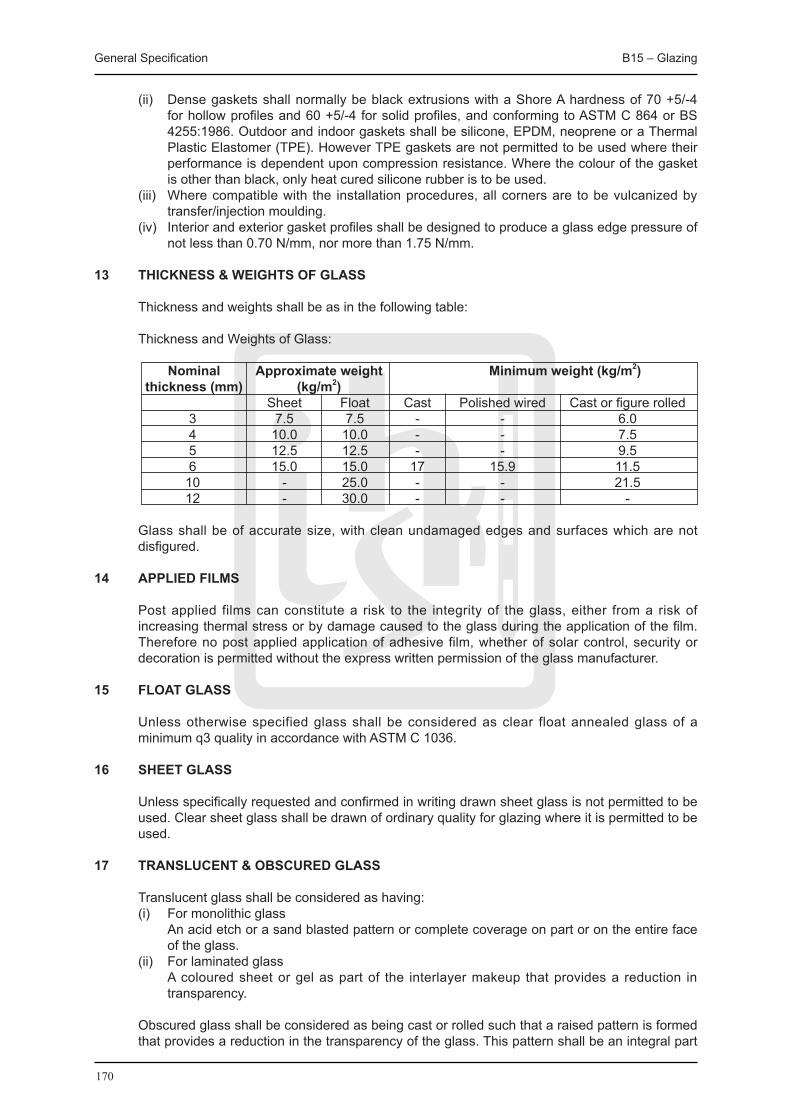
General Specification B15 – Glazing
170
(ii) Dense gaskets shall normally be black extrusions with a Shore A hardness of 70 +5/-4 for hollow profiles and 60 +5/-4 for solid profiles, and conforming to ASTM C 864 or BS 4255:1986. Outdoor and indoor gaskets shall be silicone, EPDM, neoprene or a Thermal Plastic Elastomer (TPE). However TPE gaskets are not permitted to be used where their performance is dependent upon compression resistance. Where the colour of the gasket is other than black, only heat cured silicone rubber is to be used.
(iii) Where compatible with the installation procedures, all corners are to be vulcanized by transfer/injection moulding.
(iv) Interior and exterior gasket profiles shall be designed to produce a glass edge pressure of not less than 0.70 N/mm, nor more than 1.75 N/mm.
13 THICKNESS & WEIGHTS OF GLASS
Thickness and weights shall be as in the following table:
Thickness and Weights of Glass:
Nominal Approximate weight Minimum weight (kg/m2) thickness (mm) (kg/m2) Sheet Float Cast Polished wired Cast or figure rolled 3 7.5 7.5 - - 6.0 4 10.0 10.0 - - 7.5 5 12.5 12.5 - - 9.5 6 15.0 15.0 17 15.9 11.5 10 - 25.0 - - 21.5 12 - 30.0 - - -
Glass shall be of accurate size, with clean undamaged edges and surfaces which are not disfigured.
14 APPLIED FILMS
Post applied films can constitute a risk to the integrity of the glass, either from a risk of increasing thermal stress or by damage caused to the glass during the application of the film. Therefore no post applied application of adhesive film, whether of solar control, security or decoration is permitted without the express written permission of the glass manufacturer.
15 FLOAT GLASS
Unless otherwise specified glass shall be considered as clear float annealed glass of a minimum q3 quality in accordance with ASTM C 1036.
16 SHEET GLASS
Unless specifically requested and confirmed in writing drawn sheet glass is not permitted to be used. Clear sheet glass shall be drawn of ordinary quality for glazing where it is permitted to be used.
17 TRANSLUCENT & OBSCURED GLASS
Translucent glass shall be considered as having: (i) For monolithic glass An acid etch or a sand blasted pattern or complete coverage on part or on the entire face
of the glass. (ii) For laminated glass A coloured sheet or gel as part of the interlayer makeup that provides a reduction in
transparency. Obscured glass shall be considered as being cast or rolled such that a raised pattern is formed
that provides a reduction in the transparency of the glass. This pattern shall be an integral part
General Specification B15 – Glazing
171
of the glass.
18 FIRE RATED GLASS
Wired and other specialist glasses must have been successfully tested in accordance with the relevant clauses of BS 476.
(i) Wired cast glass and wired polished glass shall have a square mesh wire 13 mm square electrically welded at each intersection that is embedded into the glass to a depth equivalent to half the glass thickness.
(ii) Wired glass is not considered a safety glass and can only be used in a non-fire rated installation with express permission.
(iii) Non insulating fire rated glass, other than wired soda lime glass should be bora silicate glass.
(iv) Insulating fire grated glass can be of any composition if the relevant fire certificate can be provided.
19 HEAT STRENGTHENED GLASS
(i) Heat strengthened glass shall be glass that has been heat treated to give increased strength, in accordance with the requirements of ASTM C 1046, to approximately twice the strength and impact resistance of untreated float glass.
(ii) To be defined as Heat Strengthened glass, the residual surface compression shall be between 24 and 52 MPa.
(iii) Glass with a surface compression in excess of 45 MPa shall be subjected to heat soak testing in accordance with the relevant procedures set out in EN 14179 Part 1:2005, including certification confirming calibration of the heat soak test oven.
(iv) Heat strengthened glass shall not be considered a safety glass.
20 FULLY TEMPERED GLASS
(i) Fully tempered glass shall be glass that has been heat treated to give increased strength, in accordance with the requirements of ASTM C 1046, to approximately four times the strength and impact resistance of untreated float glass.
(ii) To be defined as Fully Tempered glass, the residual surface compression shall be a minimum of 69 MPa, however it is recommended that the glass supplied as fully tempered shall have a minimum of 75 MPa.
(iii) It must also be noted that heat soak testing in accordance with PNAP 106, which is based upon the methodology of EN 14179:2005, must be undertaken for glass supplied as fully tempered. Therefore, it shall be subjected to heat soak testing in accordance with the relevant procedures set out in EN 14179 Part 1:2005, including certification confirming calibration of the heat soak test oven.
(iv) Fully tempered glass shall be considered a safety glass as upon fracture it would break into small fragments.
21 TINTED GLASS
Tinted glass shall be body tinted of the colour and intensity specified. This type of glass shall be considered as a heat absorbing glass when used externally and shall have a heat treatment that conforms to the ‘heat strengthened’ category of ASTM C 1046 as a minimum.
22 COATED GLASS
(i) Coated glass shall be an approved proprietary product with either (a) A metallic mirror-like reflective coating on the designated surface to the colour and of
the type and performance specified or (b) a pyrolitic or vacuum deposition low emissivity (Low-E) coating of the colour and of
the type and performance specified in the Particular Specification. (ii) All coated glass shall conform to the requirements of ASTM C 1376 as a minimum but
shall also conform to the requirements of the Particular Specification. (iii) The thermal performance and other properties of the glass shall conform to the criteria in

General Specification B15 – Glazing
172
the Particular Specification.
23 LAMINATED SAFETY AND SECURITY GLASS
Laminated Glass, dependant upon its composition can be regarded as a safety glass or a security glass.
(i) Laminated glass shall be an approved proprietary product comprising of two or more sheets of glass bonded together and incorporating a plastic interlayer, or other method of bonding, to ensure the performance specified.
(ii) Glass must conform to ASTM C 1172 as a minimum and is considered a safety glass if it has been tested to BS 6206:1981 and is in conformance with the categories A, B or C of this standard.
(iii) Other national standards that are equivalent to BS 6206:1981 are also acceptable but must be submitted and approved before the glass can be considered as a safety glass.
(iv) Where non-pyrolitic Low-E coatings are used, edge deletion of the coating is necessary unless specifically stated as not being required by the glass manufacturer.
(v) When laminated glass is used in a sloped condition, that is at angle from the vertical in excess of 10 degrees, and heat treated glass is required for thermal or strength reasons, the inner lite is to heat strengthened and not fully tempered.
(vi) Where laminated glass is used as a security glass to protect persons, it must have been tested to ensure compliance with the relevant threat level.
(vii) Certification is required for glass used in bullet resistance or blast resistant installations. (viii) The addition of an applied adhesive film, either to the external face or the internal face
will not be considered as, and does not constitute, an upgrading of the glass from that originally supplied.
24 STORAGE
Glass and plastic sheets shall be kept dry and clean during delivery and stored vertically in a well vented location, carefully protected from condensation and other moisture. There shall be air between stored glass sheets to allow air circulation unless the manufacturer has stated in writing that glass tightly packed with lining paper can be stored as delivered. In this case a time limit shall be given until glass is unpacked.
25 GLAZING COMPOUNDS
Glazing compounds shall be selected to suit the frame and glazing substrates. (i) The following compounds are permitted to be used: a) Silicone – Gunnable neutral cure silicone one part weather type sealant if glass is
retained mechanically. One or two-part structural sealant for glass not retained on all edges.
b) Polysulphide – Is permitted only if the glass is positively retained on all edges. c) Putty – Is permitted for glazing into wooden frames only. Putty for glazing to softwood
and absorbent hardwoods shall be linseed oil putty to BS 544:1969. Putty for glazing to non-absorbent hardwoods shall be an approved proprietary brand recommended by the window manufacturer for the particular application and with setting properties and unpainted life to suit the construction programme.
(ii) Compounds for glazing plastic sheets shall be compatible with the proprietary sheets and shall be either silicone or polysulphide.
(iii) All sealing compounds shall be tested for adhesion and the test reports submitted prior to the commencement of glazing.
B15.2 WORKMANSHIP
01 GENERAL
Glazing generally shall be to BS 6262:2005 and also conform to the glazing manual published by the Glass Association of North America (GANA – formerly FGMA).
Glazing shall be carried out from inside the building whenever possible. Glass and glazing
General Specification B15 – Glazing
173
materials shall be compatible with each other and the glass shall be protected from damage and staining of any kind.
Glass shall be new. Glass shall be of the specified type and quality with cleanly cut edges and sharp corners. Glass shall be inspected before installation. Defective glass shall not be installed.
02 INSTALLATION OF SAFETY GLAZING
Tempered and/or laminated glass shall be provided at the following locations: (i) Doors. (ii) Fixed and operable glazing with a vertical edge within 300 mm of a door in the closed
position and with the bottom edge less than 1500 mm above the walking surface. (iii) Fixed glazing with area exceeding one square meter, and with the lowest edge less than
450 mm above a walking surface, which is within 900 mm of such glazing; tempered and/or laminated glass is not required if there is a horizontal member with minimum 40 mm width located between 600 and 900 mm above the walking surface.
(iv) Any additional locations required by Hong Kong regulations.
03 INSTALLATION OF HEAT TREATED GLASS
Heat strengthened glass shall be provided where required by design wind pressures, anticipated thermal stress, and use in a spandrel area.
Fully tempered and/or laminated glass shall be provided only where required by Hong Kong regulations or where design pressures are beyond the capacity of heat strengthened glass.
Fully tempered glass shall also be used at locations where safety is a concern with reference to BS 6262:2005.
04 GLASS BITE
Before setting glass, frame shall be inspected for proper dimensions and squareness. Frame and/or glass size shall be adjusted as required to meet specified requirements for glass bite dimensions and glass edge clearance.
Except as otherwise specified, BS 6262:2005 shall be complied with. A minimum nominal glass bite of 13 mm shall be provided. Where joint movement shall result in variable glass bite, nominal bite shall be increased to provide 10.0 mm minimum bite and 6.0 mm minimum edge clearance. In no case shall the front and back clearances be less than 5.0 mm. GANA manual shall be referred for further information.
05 GLASS STOPS AND APPLICATION OF SEALANTS
Stops shall be removed and replaced and sealant shall be applied as required for a complete glass installation.
06 REPLACEMENT OF DAMAGED GLASS
Glass shall be left in crates until just prior to installation. Any glass which breaks or sustains edge damage, surface damage or damage to reflective coating as defined in the Particular Specification shall be replaced.
07 STRUCTURAL SILICONE
Structural silicone joints shall be cleaned, primed and masked for a maximum of 8 hours before applying the silicone.
Glass shall be temporarily clamped during cure of structural silicone. After sufficient cure, clamps shall be removed and any gaps in silicone shall be filled.

General Specification B15 – Glazing
174
Glass and aluminium shall be masked during application of structural silicone. Masking shall be removed immediately after tooling sealant.
Structural silicone shall not be applied to edges of insulating glass units, or to edges of laminated glass units. Sealants used as weather seals shall not be adhered to, or placed against, the edge of a laminated glass unit inter-layer.
08 PREPARATION OF SURROUNDS
The preparation of the surrounds for acceptance of the glazing is important.
All surrounds shall be free of any foreign matter and be cleaned to accept the sealing compound in accordance with the requirements of the sealant manufacturer.
The application of sealant to unprepared substrates is not permitted.
Aluminium surrounds shall be anodized or painted with an Architectural factory applied finish. Alternatively a chromate conversion coating is acceptable.
For all other materials, including stainless steel, details of the finish and cleaning procedures shall be submitted prior to commencement of glazing.
09 EXTERNAL GLAZING GENERALLY
External glazing shall be wind tight and watertight on completion whether the glazing has been carried out with glazing compounds or gaskets.
10 GLASS ORIENTATION
Where the glass has an integral cast or rolled pattern on one surface, that surface should be glazed facing outward.
Where the glass has a sand blasted or acid etch pattern on one surface, that surface should be glazed facing inward.
For glass with metallic coatings, reflective and Low-E, confirmation of the correct orientation shall be made by the glazing supervisor.
11 ALIGNMENT OF WIRED GLASS
Directionally patterned or wired glass shall be fixed with the pattern or wires parallel to surround and wire shall be aligned in adjacent panes. Cut edges of wired glass shall be painted with black bituminous paint to inhibit rusting.
12 EDGE CLEARANCE
Edge clearance shall be in accordance with the recommendations of the manufacturer or GANA, subject to a minimum clearance of 3 mm.
13 EDGE COVER
Edge cover is generally dependent on glass thickness and shall be in accordance with the recommendations of the manufacturer or GANA.
14 BEDDING & TOOLING
The application and tooling of all sealants and glazing compounds is important.
No voids or spaces shall be left in backing or bedding compounds and that there shall be no metal or wood to glass contact.

General Specification B15 – Glazing
175
Sealing compound shall be tooled as follows: (i) To top and side edges - flush with top of rebate or bead. (ii) To bottom edges - with a suitable angle to shed water.
15 GLAZING WITH PUTTY
Glazing with putty is only permissible in wooden frames.
Glass shall be secured to wood surrounds with glazier’s sprigs at 450 mm (maximum) centres.
Back putty shall be of regular thickness and 2 mm (minimum).
Front putty shall be formed to neat triangular fillet, stopping 2 mm short of sight lines.
Opening lights shall be left in closed position until putty has set sufficiently to prevent displacement of glass.
16 PROTECTION OF PUTTY
Linseed oil putty shall be sealed as soon as sufficiently hard and within the times recommended by their manufacturers, with primer and paint.
17 GLAZING WITH BEADS
There shall be no break in the air seal at the rear face of the glass and if necessary, beads shall be bedded in glazing compound for external glazing.
Wood beads shall be secured with rustproofed panel pins or with countersunk brass screws and cups at 200 mm (maximum) centres and 75 mm (maximum) from each corner.
Metal beads supplied with metal windows shall be removed and refixed.
18 SEALING
When specified joint between the glass and bead shall be sealed with an approved silicone sealant. All manufacturer recommended cleaning processes shall be followed.
19 GLAZING ALUMINIUM WINDOWS
Aluminium windows shall be glazed by the specialist supplying and fixing the windows.
20 LOUVRE BLADES
Louvre blades shall have edges parallel, and ground to remove sharp arises.
21 CLEANING All smears and excess glazing compound shall be removed.
Mortar, plaster or concrete spillage and paint drips shall be removed whilst wet.
Glass shall be left clean inside and out, and free from scratches.
22 MAKING GOOD
Glass or fixing materials broken or damaged shall be replaced before practical completion, and area shall be redecorated if necessary.

176
177
B16 Plumbing and Sanitary Fitments
General Specification B16 – Plumbing and Sanitary Fitments
178
B16 PLUMBING AND SANITARY FITMENTS
B16.1 WATER SUPPLY PIPE WORK, INCLUDING EXTERNAL WATER MAINS
B16.1.1 MATERIALS
01 GENERAL All plumbing works shall comply with the requirements of Water Authority and Waterworks
Regulations.
Pipe work under this section shall include: (i) External water mains and fire services mains within the site boundary. (ii) Rising water and fire services mains. (iii) Internal water distribution pipe work. (iv) Washouts, overflows and all connections to tanks.
Dry risers and fire services distribution pipes and fittings from the roof tank or the rising main to the individual discharge points shall be included in the fire services installation part of the Works.
For cold and hot potable water supply systems, copper pipes or any alternative materials which are acceptable to Water Authority and incorporated into Schedule 2 of Waterworks Regulations for use in fresh water inside service shall be used.
For make up water supply system of air conditioning system or fountain system, steel pipe or UPVC pipe shall be used where specified.
For flushing water supply systems, ductile iron or plastic pipes as specified shall be used. Ductile iron pipe riser shall be used when booster/transfer pumping system or deep bore well is adopted.
02 DUCTILE IRON PIPES
Ductile iron pipes and fittings shall comply with BS EN 598 (replacing BS 4772), metallic zinc coated.
03 STEEL PIPES
Steel pipes shall comply with BS EN 10255, medium grade and hot dip zinc coated. Fittings for steel pipes shall be malleable cast iron with screw fittings complying with BS 143 and BS 1256 hot dip zinc coated.
Stainless steel pipes shall comply with BS EN 10312:2002 light gauge stainless steel tubes, grade 304 for potable water supply and grade 316 for flushing water supply. Capillary or compression fittings shall be either of copper alloys complying with BS EN 1254-2:1998 or stainless steel complying with BS 4386:Part 3.
04 COPPER PIPES
Copper pipes shall comply with BS EN 1057:2006, Table X in half hard condition. Fittings for copper pipes shall comply with BS EN 1254-2:1998, Table 6.
05 PLASTIC PIPES
Plastic pipes shall be unplasticised PVC pipes complying with ISO 4422, Part 1 and 2 (replacing BS 3505) of the pressure rating class D or higher as specified, with fittings complying with ISO 4422, Part 3 (replacing BS 4346:Pt. 1 and Pt. 2).
General Specification B16 – Plumbing and Sanitary Fitments
179
06 CISTERNS
Cistern for cold water storage may be made of glass fibre reinforced plastic complying with BS EN 13280:2001:Pt. 1 or other material approved by the Water Authority.
07 DRAW-OFF TAPS AND VALVES
Screw-down type draw-off taps and stop valves generally shall comply with BS 1010-2:1973.
Valves and taps installed in public areas, not intended for public use, shall be housed in vandal resistant and corrosion resistant enclosures.
All valves shall be protected after installation for handing-over in perfect condition on completion.
All valves shall be suitable for both the working and test pressures of the piping system in which they are installed.
Unless otherwise specified, all valves shall have a working pressure of not less than 1370 kN/sq. m.
All valves shall be pressure tested in accordance with the relevant British Standard by the valve manufacturer before leaving the factory. Test certificate/ report from laboratories approved by the Water Authority confirming that the valves have been tested in conformance with this specification to be produced upon request. Isolating valves for general purpose other than mains (potable) services shall comply with:
(i) BS EN 1171:2002 Cast Iron Gate Valves (ii) BS EN 12334:2001 Cast Iron Check Valves (iii) BS 5154 Copper Alloy Gate and Check Valves
Isolating valves at incoming water mains shall comply with BS EN 1074-2:2000.
Manually operated valves shall be closed by turning the handwheel in a clockwise direction when facing the handwheel. All valves shall be provided with an indicator to show the open and shut position.
Isolating valves shall be of the full-way solid or split-wedge disc-type and handwheel operated.
All bronze valves shall be of the screwed female-end connections and all cast iron valves shall be of the flanged-end connections.
Threads in screwed-end connections shall comply with BS 21 and flanges of flanged-end connections shall comply with BS EN 1092-2:1997.
Unless otherwise specified, non-return valves shall be of the hinged-swing or the recoil type, suitable for both vertical and horizontal installations.
When the valve is installed vertically, the flow shall be in an upward direction.
Bronze swing non-return valves shall have screwed type cap. Cast iron swing non-return valves shall have the cap and body bolted together.
Recoil or spring-type non-return valves shall have a flow area not less than the cross-sectional area of the connected pipework and shall be non-slam in operation. The valves shall be designed to close before reversal of flow starts.
Hinge pins and springs shall be of stainless steel.
Wafer-type spring non-return valves are acceptable, provided the body ends shall be capable of matching connecting flanges complying with the requirements of BS EN 1092-2:1997.
General Specification B16 – Plumbing and Sanitary Fitments
180
Puddle flanges for fresh water and fire services water systems shall be gunmetal. Puddle flanges for salt water systems shall be cast iron.
08 PRESSURE REDUCING VALVES
The pressure reducing valve shall be of spring controlled diaphragm operated type. The body shall be bronze complying with BS EN 1982:2008 LG2 or cast iron complying with BS EN 1561:1997 Grade 220 or equivalent. The trimming shall be bronze complying with BS EN 1982:2008 LG2 or equivalent. The diaphragm shall be synthetic rubber capable of withstanding the stresses during operation and shall be approved by the Water Research Centre, United Kingdom for use in potable systems. The diaphragm spring shall be of steel suitable for the working pressure. The valve spring shall be of 13% chromium stainless steel complying with BS EN 10090:1998.
Thread-in screw and connection shall comply with BS 21 or the flanged end connection shall comply with BS EN 1092-2:1997.
The operating pressure range shall be suitable for the particular application.
The valve shall be sized large enough to satisfy the maximum flow at the rated pressure. The performance curve showing the amount of pressure reduction against flow rate shall be to the satisfaction of the Contract Administrator.
Each valve shall be hydraulic tested at 1.5 times the nominal pressure of the valve for a period of not less than 1 minute at the factory.
Type test certificate/report from the independent and reputable laboratories, for the verification of the hydraulic pressure requirements and material used, shall be produced upon request.
09 BALL VALVES
Ball valves shall be of the slow closing type, unless otherwise specified. The valve body shall be robust and shaped to give a good flow pattern. The valve piston shall close in the direction of flow such that the pressure in the Main shall tend to keep the valve closed and that the piston seal is afforded protection from the flow by the piston.
All internal parts shall be easily removable for maintenance with the face and piston seals easily replaceable.
Ball floats shall comply with BS 1968 or BS 2456 and shall be constructed of tinned copper for fresh water application and of neoprene coated copper for flush water application. All ball floats shall be spherical.
Lever arms shall be of stainless steel for flush water application. Ball valves for tanks for sizes 50 mm and under shall be bronze complying with BS 1212:Part 1, suitable for high pressure. For salt water systems the bronze shall be zinc free.
Ball valves for tanks for sizes over 50 mm shall be cast iron body with gunmetal piston, seat and guide, suitable for high pressure. For salt water systems ball valves shall be of cast iron body with zinc free bronze piston, seat and guide.
Where ball valves are installed inside sump tanks, extended guide pipes with submerged discharge ends shall be provided after ball valves. Guide pipes shall be of diameters not less than the incoming pipes and shall be holed as appropriate to avoid back-siphoning.
10 BALL VALVES FOR FLUSHING CISTERNS
Ball valves for flushing cisterns shall be diaphragm type float operated valves complying with BS 1212:Part 3 with rubber or plastics diaphragms suitable for high, medium or low pressure. Metal parts of valves shall be suitably coated to prevent corrosion.
General Specification B16 – Plumbing and Sanitary Fitments
181
11 FLUSHING VALVE
Flushing valve shall be corrosion resistant, made of brass, stainless steel or high grade thermoplastics and activated by simply pressing on a push-button or lever.
The volume of water per flushing cycle for water closet fitment shall be ranging from 7.5 litres to 15 litres. In the case of urinals, the discharge volume shall be not less than 4.5 litres for every basin or stall, or for every metre of a trough urinal.
The flow rate of the flush water shall be adjustable. The flush valve shall maintain a minimum of 1.5 litres/second flow rate.
The valve shall have such feature to allow it to go through the complete flush cycle and then shut off automatically, regardless of whether the handle is held down or released. Such automatic closure shall take place slowly and progressively without hammering effect.
12 STAMPING OF TAPS AND VALVES
Taps and valves shall be: (i) Stamped with BSI certification mark. (ii) Fittings approved by the Water Authority.
13 jOINTING MATERIALS
The use of jointing materials based on red lead shall not be permitted. Solder used for jointing copper or copper alloy potable water pipes shall be lead free and comply with BS EN 1254-1:1998.
14 INSULATING MATERIALS
Insulating materials for pipes and cylinders generally shall comply with BS 5422:2009, have a thermal conductivity of 0.04 W/mºC, be suitable for use up to 75ºC and have an outer layer of canvas calico scrim or plastic sheet.
The fire performance of all insulating materials shall be designated P when tested in accordance with BS 476:Pt. 5 or BS 476:Pt 13:1987. The insulating material shall not generate noxious and toxic fumes. When insulation is used on the exterior of pipe work that is exposed within the building, the complete assembly of materials installed shall have a rating for the surface spread of flame of not less than that for the surface of the wall or ceiling that it transverses.
Felt, hair felt, asbestos rope or other asbestos based materials and the like shall not be used. All materials shall be fire resistant and non vermin supporting.
Fixing bands shall be of non-corrosive metal.
B16.1.2 WORKMANSHIP
01 GENERAL
Water supply installation shall generally comply with BS 6700:2006+A1:2009.
02 FIXING PIPES
All pipes shall be installed to falls of 1 in 100 (minimum) to prevent air locks. Pipe runs above electrical switchgear and at locations which may cause obstructions inside pump rooms shall be avoided. Pipes shall not be fixed to ceilings of pump rooms.

General Specification B16 – Plumbing and Sanitary Fitments
182
03 PIPES ON FLAT ROOFS
Pipes on flat roofs shall be supported at least 150 mm above roof finish on concrete blocks and pipe brackets or PVC sleeves. UPVC pipes shall be painted with white acrylic paint.
04 jOINTING PIPES
All pipe joints shall be carried out in accordance with the manufacturer’s instructions.
Galvanized steel pipes of sizes up to and including 100 mm shall be jointed with screwed fittings. Screwed flanges shall be employed only for connection to flanged valves or equipment.
Galvanized steel pipes of sizes of 150 mm and above shall be jointed with screwed flanges.
All ductile iron pipes shall be jointed with flanges or flanged fittings. Flanges shall comply with BS EN 1092-2:1997.
Joints between different materials shall be made with proper adaptors.
05 STOP VALVES
Where visible internally in the completed work, chromium plated screw-down type stop valves shall be fitted in an easy clean pattern.
06 FIXING OF FLUSHING VALVE
The pipe work shall be drained thoroughly prior to the installation of the flushing valve into service.
No pipe sealant or plumbing grease shall be allowed on any flushing valve components or couplings unless otherwise specified in the manufacturer’s literature.
The flushing valve shall be installed with its outlet connecting to a vertical down pipe.
07 CONNECTIONS TO CISTERNS AND TANKS
Generally, when connecting pipes to cisterns and tanks, cisterns and tanks shall be properly supported to avoid undue stress on the pipe connections. Holes shall be correctly positioned for the connection of pipes to cisterns and tanks. All debris and fillings shall be removed. Holes in cisterns and tanks shall not be formed by flame cutters.
08 CONNECTING STEEL PIPES TO STEEL OR GRP CISTERNS
Steel pipes shall be connected to steel or glass fibre reinforced plastics cisterns and tanks by either:
(i) backnuts and washers both inside and outside. (ii) by using bolted or welded flanged connections.
09 CONNECTING COPPER OR PLASTIC PIPES TO STEEL OR GRP CISTERNS
Plastic pipes shall be connected to steel or glass fibre reinforced plastics cisterns by a backnut to the inside. Corrosion resistant support washers shall be used on both the inside and outside of the cistern or tank.
Copper pipes shall be connected to GRP cisterns or tanks in a similar manner. Copper pipes shall not be connected to steel cisterns or tanks.
10 CONNECTIONS TO CONCRETE TANKS
Pipes shall be connected to concrete tanks with short thread flanged connections having a
General Specification B16 – Plumbing and Sanitary Fitments
183
puddle flange either cast or welded on. The connections shall be properly aligned both in the horizontal and vertical planes when being cast into the concrete. The puddle flange shall be compacted around to ensure a water tight joint.
11 OVERFLOW PIPES
Overflow pipes shall be one pipe size larger than the inlet pipe and in no case less than 25 mm diameter and shall be extended to terminate in conspicuous positions.
The top of the overflow pipe shall be not less than 25 mm below the invert of the inlet pipe.
12 ACCESS COVERS AND FRAMES
Galvanized access covers and frames shall be fitted to water tanks.
Double sealed access covers shall be fitted to potable water tanks.
Access cover frames shall be bedded and haunched in cement mortar and seal covers with grease.
13 INSULATION
Insulating materials in accordance with BS 6700:2006 + A1:2009 shall be used.
Hot water service pipe work shall be fitted with insulating material.
Insulating quilts shall be secured to cylinders with bands, or by binding with tape or cord.
14 PROTECTION OF UNDERGROUND PIPES
Steel pipes laid below ground shall be protected by wrapping with an approved protective petroleum based tape.
15 PIPES UNDER ROAD, ETC.
Pipes crossing under roads shall be passed through in ducts of similar construction to cable ducts.
16 CLEANING OUT
Tanks and cisterns shall be cleaned out. Pipe work, including overflows, shall be flushed out with fresh water on completion.
17 TESTING
Service and distributing pipes shall be tested to the satisfaction of the Contract Administrator, as follows:
(i) Slowly fill the installation with water, with the highest draw-off point open to allow air to be expelled from the system.
(ii) Subject the pipes, pipe fittings and connected fitments to a test pressure of 1.5 times the maximum working pressure, with the pressure applied and maintained for at least one hour. Note any loss of water or leakage.
(iii) Check each draw-off tap. Show fitting and float-operated valves for rate of flow against the specific requirements.

General Specification B16 – Plumbing and Sanitary Fitments
184
B16.2 SANITARY FITMENTS
B16.2.1 MATERIALS
01 GENERAL
Certain standard sanitary fitments may be supplied by the Employer, as scheduled on the drawings. These may include brackets, waste fittings, traps, taps, valves, chains and plugs & all fittings which relate to fixtures.
All other sanitary fitments as specified shall be provided. Samples of all sanitary fittings shall be submitted for approval.
(i) All sanitary fittings unless specified otherwise shall be white, from an approved manufacturer, generally ensuite and completed with all necessary fittings.
(ii) Wastes and bath overflows, chains and stays, shall be chromium plated brass complying with BS EN 274-1:2002.
(iii) Taps and combination tap assemblies shall be chromium plated brass complying with BS 5412.
02 BATHS
Baths shall be vitreous enamelled sheet steel complying with BS 1390 with adjustable feet for 75 mm seal trap holed at end for and including combined waste and overflow complying with BS EN 274-1:2002 complete with plug and chain and chromium plated brass taps complying with BS 5412.
03 SHOWER TRAYS
Shower trays shall comply with BS 6340: Pt 8 or ABS capped resin-stone.
04 SHOWER FITTINGS
Shower fittings shall be approved chromium plated brass easy clean valve, thermostatic valve or as specified fitted with one of the following:
(i) Concealed or exposed shower fittings for lever with flexible hose 1500 to 1800 mm long c/w chrome plated sliding bar and head. (ii) Time-delayed control for adjust 15 sec. to 30 sec. cold or mixer. (iii) Self cleansing swivel-jointed rose with an adjustable spray.
05 TAPS
Taps shall be: (i) Sensor tap complying with BS EN 816:1997. Operating pressure between 0.3 – 10 bar.
Flow rate 2 - 6 litre per min. Max. water temp. 80 degree aerator. Self cleaning. Turn-off control pre-set 0 – 3 sec.
(ii) Sensor mixer or cold. (iii) Self-closing tap for time delay function. (iv) Bib tap.
06 WASH BASINS
Wash basins shall comply with BS 1188:1974 and shall be made from vitreous china complying with BS 3402 of the following types as specified:
(i) Under counter basin with overflow. (ii) Wall hung basin with or without pedestal as specified. (iii) Semi-recessed basin with or without overflow as specified. (iv) Counter top basin with or without overflow as specified.

General Specification B16 – Plumbing and Sanitary Fitments
185
07 STAINLESS STEEL SINKS
Sinks shall comply with BS 1244: Part 2:1988, stainless steel grade 304 (0.8 to 0.9 mm) or grade 316 (1.5 to 1.6 mm) minimum thick, with satin finish to the size and configuration shown on the drawings with overflow and sound deadening pads under the sink and drainers.
Sinks shall be provided with an effective means of attaching a bonding conductor which shall be accessible to the electrician after the sink has been installed.
08 CLEANER’S SINKS
Fireclay cleaner’s sink shall comply with BS 6340 in white colour, fitted with a 38 mm hole for chrome plated waste and provided with or without overflow as specified.
09 WATER CLOSETS (W.C.)
Water closet pans shall be vitreous china washdown with horizontal outlet complying with BS EN 997:2003, white plastic single ring seat and cover with plastic fixing bolts all to BS 1254 and flushing cistern to BS 7357, complete with 7.5 litres max capacity flushing apparatus, discharge pipe, ball valve and overflow, of one of the following types as specified:
(i) Low level plastic. (ii) High level plastic. (iii) Low level vitreous china. (iv) Close coupled vitreous china.
Sensor valve where specified for automatic flushing shall comply with BS EN 12164 CW602N. Operating pressure shall be 0.5 – 10 bar rinse.
Time-off control shall be approximately 10 sec. and be remotely adjustable from 1.5 – 30 sec. Dry battery shall be 6V Lithium 2 CR5. A/C operation shall be 220 to 230/50z; voltage 6V.
Sensor fittings shall be suitable for use in salt water application.
10 URINALS
Urinals shall be vitreous china bowl type complying with BS 5520:1977 with 50 mm diameter of waste outlet, complete with vitreous china automatic flushing cistern complying with BS 1876:1990, chromium plated flush pipes and spreaders to suit the number of appliances in the range as follows:
(i) 4.5 litres to serve single bowl. (ii) 9 litres to serve 2 bowls. (iii) 13.5 litres to serve 3 bowls.
Sensor valve shall comply with BS EN 12164 CW602N. Operating pressure shall be 0.3 – 10 bar rinse. Time-off control shall be approximately 9 sec. and be remotely adjustable from 7 – 22 sec. Dry battery shall be 6V Lithium 2 CR5. A/C operate shall be 220-230/50z; voltage 6V.
Sensor fittings shall be suitable for use in salt water application.
11 FIRECLAY SLAB URINAL
Fireclay slab urinal shall comply with BS 6340 in white colour to the size and configuration shown on the drawings. The length of urinal slab shall be max. 4200 mm.
12 STAINLESS STEEL SLAB URINAL
Stainless steel slab urinal shall comply with BS 4880-1:1973 grade 316 1.5 to 1.6 mm thick, with satin finish to the size configuration shown on the drawing with sound deadening pads behind the slab. Custom made size slab urinal may be straight, L-shaped or U-shaped as shown on the drawings with join and the length of slab not exceed 4200 mm.

General Specification B16 – Plumbing and Sanitary Fitments
186
13 STORAGE
Fitments shall be stored under cover and kept dry. Fitments shall be separated with dust sheets or polythene sheets when not in manufacturer’s own packing.
All metal sinks etc. shall be stored on a level surface to prevent twisting. Contact with cement or lime shall be avoided.
14 TRAPS
Traps shall have 75 mm seal, unless otherwise specified. Cast iron traps shall comply with BS 416-1:1990, Table 18. Plastic waste traps shall comply with BS EN 274-1:2002 or shall be of an approved proprietary brand.
15 SILICONE SEALANT
Silicone sealants shall comply with BS EN ISO 11600:2003 Type B in white colour or match sanitary fixtures.
B16.2.2 WORKMANSHIP
01 FIXING GENERAL
All necessary jointing compound, mortar, lead plugs and other accessory materials shall be provided. Brackets shall be cut and pinned, or plugged and screwed, and all necessary connections to water supply services, overflows, wastes and ventilating pipes shall be made.
All sanitary fitments shall be adequately supported when being fixed. Where build-in types of brackets are used, the tails of such supports shall be built into the wall at least 75 mm and where wall fixing types are used, the wall finish shall have been arranged to make provision for them.
All fittings shall be pointed as necessary with the following: (i) White or coloured cement. (ii) White or coloured silicone sealant. All fittings shall be de-greased and dried before the
application of sealant.
Discharge pipes and water supply pipes shall be installed before fixing the fitments. Protective coverings shall be retained during and after fixing when practicable and cleaned off when required.
Any fitments which are chipped or scratched shall be replaced either before or after fixing.
02 WASTE OUTLETS
Waste outlets to wash basins, sinks, baths and showers shall be bedded in proprietary jointing compound.
03 FIXING TAPS
Taps shall be fixed to make a water tight seal with the sanitary fitment. Hot tap shall be placed to left of cold tap as viewed by the user. Hot/Cold markings shall be correctly applied and located.
04 CONNECTIONS
Connectors shall be provided for service and waste pipes.
General Specification B16 – Plumbing and Sanitary Fitments
187
05 FIXING WASH BASINS
Wash basins shall be supported on one of the following as specified: (i) Pair of concealed painted steel brackets. (ii) Pair of porcelain enamelled towel rail brackets. (iii) Set of porcelain enamelled or chromium plated legs and brackets. (iv) Approved proprietary brackets to suit the basins. (v) Counter top as shown on drawings or manufacturer’s details.
Water tight seal between the walls and the basins shall be made by using silicone sealant.
06 FIXING W.C. PANS W.C. pans shall be fixed as follows: (i) Pedestal type (a) Bed W.C. pans on concrete floors in white lead putty or other non-hardening
compound. If cement mortar is used for bedding, it shall be not richer than 1:6, and a thin layer shall be applied only to that part of the pedestal which is in contact with the floor. Fix with No. 14 SG round-headed brass screws 70 mm long with domed plastic inserts in colour to match to fixture.
(b) Joint W.C. pans to soil or drain pipes with approved PVC W.C. pan connectors to BS 5627 or other approved type.
(ii) Squatting type (a) Bed W.C. pans in concrete floors in cement and sand mortar 1:3 and joint to soil or
drain pipes in similar mortar. (iii) Wall hung type (a) Fix wall hung type WC pans to load bearing walls or support frame by non-ferrous
fixing bolts. Water tight seal between the walls and the edge of the W.C. pans shall be made by appropriate sealant.
07 FIXING URINALS
Urinals shall be fixed as follows: (i) Slab type (a) Bed channel outlet to waste connector in proprietary jointing compound. (b) Bed treads in cement and sand mortar 1:3 with fall towards channel. Completely fill space behind slabs with cement and sand mortar 1:5. (c) Joints shall be 3 mm (maximum) wide. Rake out joints to a depth of 5 mm and point
flush with an approved proprietary white grout. (ii) Stall type (a) Bed outlet to waste connector in proprietary jointing compound. (b) Bed base and overlap facing in cement and sand mortar 1:3. (iii) Wall type (a) Fix bowl and division to wall with brackets, concealed hangers or screws, as required.
08 FIXING BATHS
Supports for the bath shall be adjustable to permit the bath to be properly levelled when installed. Bearing plates shall be provided under bath feet.
A permanent watertight seal between the wall and the edge of the bath shall be made by using silicone sealant. All bath surfaces shall be properly protected up to completion stage.

188

189
B17 Drainage
General Specification B17 – Drainage
190
B17 DRAINAGE
B17.1 SURFACE WATER DRAINAGE ABOVE GROUND
B17.1.1 MATERIALS
01 GENERAL All material and drainage works shall comply with the requirements of the Buildings Ordinance
and relevant regulations.
Generally all pipes shall be marked permanently in English or Chinese with the following: (i) Nominal size (ii) Name of manufacturer (or Trade Mark) (iii) Standard to which pipes are manufactured (iv) Other information required by the particular standard
Markings shall be in colour and marked at intervals laid down in the particular standard.
02 CAST IRON RAINWATER PIPES
Cast iron rainwater pipes shall be as follows: (i) Rainwater pipes gutters and fittings for use externally shall comply with BS 460:2002. Rainwater pipes shall have Type A or B sockets without ears. Holderbats shall be cast iron with 8 mm brass or cadmium plated steel screws, bolts and
washers. Gutters shall be half round or ogee section or as specified, with galvanised mild steel
brackets. (ii) Cast iron rainwater pipes and fittings for use internally shall comply with BS 416:1990 with
Type A or B sockets without ears. Holderbats shall be cast iron with 8 mm brass or cadmium plated steel screws, bolts and
washers. Cast iron roof outlets shall comply with BS 416:1990 Table 20, 21, 22 and 23. Domical
gratings shall be provided if specified.
03 PLASTIC RAINWATER PIPES
Plastic rainwater pipes not exceeding 80 mm diameter, gutters and fitting shall comply with ISO 4435 (replacing BS 4576) or other approved rainwater system. All internal pipe work and external pipes exceeding 80 mm diameter and fittings shall comply with ISO 3633 (replacing BS 4514). Colour of plastic pipes gutters and fittings shall be black, “terra-cotta”, light grey, or white as specified. All metal fittings shall be galvanized or plastic coated.
Combination of products from different manufacturers shall not be permitted unless otherwise approved.
Plastic roof outlets shall be an approved proprietary make complete with sealing flange and screw fixed flat or domical grating.
B17.1.2 WORKMANSHIP
01 FIXING GUTTERS
Gutters shall generally be laid to falls of 1 in 300 (minimum).
02 CAST IRON PIPES AND GUTTERS
Pipes shall be jointed with gaskin and cold caulking compound.
Cast iron gutters shall be fixed with screwed brackets at 1 m (maximum) centres.
General Specification B17 – Drainage
191
Gutters shall be jointed with jointing compound and bolted together.
03 PLASTIC PIPES AND GUTTERS
Plastic pipe and gutters shall be jointed in accordance with the manufacturer ’s recommendations.
Roof outlet gratings shall not be fixed until after all other work at roof level is completed. Outlets that are contaminated in any way shall be replaced.
04 TESTING
(i) Internal pipes shall be tested with air, using approved testing equipment, as follows: (a) Isolate the length of pipe to be tested and plug ends. (b) Test with air at a pressure equal to 38 mm water gauge. (c) Maintain this pressure for 3 minutes. (ii) External gutters and pipes shall be tested with water as follows: (a) Plug the gutter outlet(s). (b) Fill the gutter with water to the overflow level or to the lower level of the freeboard. (c) Check visually for leakage after 5 minutes. (d) To satisfy the Contract Administrator that gutters are laid to correct falls and that
gutters and pipes are unobstructed. (e) Make good all defects revealed by the tests.
B17.2 FOUL WATER DRAINAGE ABOVE AND BELOW GROUND LEVEL
B17.2.1 MATERIALS
01 CONCRETE PIPES
Precast concrete pipes and fittings shall comply with BS 5911-1:2002, BS EN 1916:2002 with flexible joints of spigot and socket or rebated type. Concrete pipes shall have wall thickness and strength not less than those specified.
Class and nominal internal diameter of concrete pipe shall be as specified.
02 DUCTILE IRON PIPES
Ductile iron pipes and fittings shall comply with BS EN 598:2007, metallic zinc coated.
03 CAST IRON PIPES
Cast iron soil, waste and ventilating pipes and fittings shall be: (i) To BS 416:1990 with type A or B sockets without ears. (ii) All spigot spun pipes from an approved manufacturer with flexible joints to BS EN
877:1999+A1:2006.
Holderbats shall be cast iron with 8 mm brass or cadmium plated steel bolts and nuts.
04 SUBSOIL DRAIN PIPES
Subsoil drain pipes shall be: (i) Concrete porous drain pipes to BS 5911: Pt. 114. (ii) Unglazed clayware field drain pipes and junctions to BS 1196:1989. (iii) Perforated vitrified clayware to BS 65:1991 as Clause 23.04. (iv) Perforated plastics pipes and fittings to BS 4962:1989.
05 STEEL PIPES
Steel pipes shall comply with BS EN 10255:2004 medium grade and hot dip zinc coated. Fitting
General Specification B17 – Drainage
192
for steel pipes shall be malleable cast iron screwed fittings to BS 143 and 1256:2003, and hot dip zinc coated.
06 PLASTIC PIPES
Plastic soil and ventilating pipes and fittings shall comply with ISO 3633 (replacing BS 4514).
Plastic waste pipes and fittings shall comply with BS 5255:1989. W.C. connectors shall comply with BS 5627:1989.
Pipes and fittings shall be suitable for their intended use, particularly where non-domestic effluents or hot liquids in kitchens, laboratories etc. may be discharged into the system.
07 GRANULAR BEDDING
Recycled or non-recycled granular bedding material shall be clean, hard, durable, crushed rock or crushed concrete, broken stone, hard brick, concrete, or other comparable hard inert, approved material to pass a 25 mm BS sieve, but shall be retained on a 5 mm BS sieve. The material shall be tested as specified.
08 CONCRETE WORK
Concrete shall be as specified in relevant section of specification and used as follows: (i) Grade 20/20 - channels, manholes, inspection chambers, gullies, catchpits and all
reinforced concrete work. (ii) Grade 10/20 - pipe bedding, pipe haunching, pipe surrounds and all other work. (iii) Grade 10/40 - filling.
09 MORTAR
Mortar for bedding covers or for rendering shall consist of one part cement and three parts clean well graded sand with just enough water to give plastic consistency.
10 CAST IRON DRAINAGE GOODS
Standard manhole covers and frames shall comply with BS EN 124:1994 with coating to BS 4164:2002 of the type and grade specified.
Cast iron covers, gratings, overflow weirs and frames shall be clean, free from air holes, sand holes, cold shuts and chill, neatly dressed and carefully fettled. Castings shall be free from voids, whether due to shrinkage, gas inclusions or other causes.
Manhole steps shall comply with BS EN 13101:2002 of malleable iron to BS EN 1562:1997 hot
dip galvanized.
11 BALLOON GRATINGS
Balloon gratings shall be: (i) Galvanized steel wire or copper wire balloons. (ii) Plastic balloons of an approved proprietary brand.
B17.2.2 WORKMANSHIP
01 GENERAL
Foul water drainage above ground shall generally comply with BS EN 12056-2:2000.
02 ACCESS DOORS IN PIPES
Bolted access doors or inspection units shall be provided to all branches and bends (other than
General Specification B17 – Drainage
193
ventilating and anti-syphon pipes) and at the foot of main soil stacks. Access doors to cast iron soil stacks shall be fitted with gun metal bolts.
03 PIPE HANDLING
Pipes shall be taken care of to prevent chipping, spalling or other damage.
Pipes shall not be rolled over rough ground.
Timber skids of adequate strength may be used for heavy pipes.
Pipes off loaded on skids shall be suitably wrapped to avoid risk of damage.
Pipes shall not be lifted by slings or chains passing through bore.
04 PIPE STACKING
Pipes shall be supported under barrel with sockets overhanging.
Bottom layer of pipes shall be adequately chocked in stack to prevent stack collapse.
Pipes shall not be stacked higher than 2 m.
05 SETTING OUT
The centerline and top width of trench marked shall be set out accurately by means of suitable pegs and offset side check pegs.
Temporary benchmarks shall be established in stable positions. Strong site rail, planed true, painted in contrasting colours shall be erected and fixed to rigid posts across center of each manhole. The centerline of pipeline shall be indicated on sight rail and its height related to an even dimension to invert level of pipe. At least three rails shall be provided on each gradient at maximum spacings of 30 m. Length of travellers used between sight rails shall be checked at frequent intervals.
06 LEVELS OF EXISTING DRAINS
Before commencing excavation, invert levels of existing drains, sewers and manholes against levels shown on drawings shall be checked.
07 BEDDING AND LAYING OF PIPES
Only one type of pipe and bedding within any individual drain length between any two drainage chambers shall be used.
08 TIMING OF BEDDING AND LAYING OF PIPES
Laying of pipes shall be proceeded without delay on completion of excavation. Brick or other hard material shall not be used under pipe for temporary support.
09 LAYING PIPES
Pipes shall be laid single, straight to line and true to gradient with sockets facing upstream starting at the downstream end of the trench.
10 GRANULAR BEDDING
Granular bedding shall be compacted and trimmed to correct gradient and shaped under barrel and pipe sockets to ensure uniform support along whole barrel length.
General Specification B17 – Drainage
194
After laying, jointing and testing pipeline, granular bedding material shall be compacted concurrently on each side of the pipe to specified level.
11 NATURAL BEDDING
Natural bed shall be accurately trimmed to provide uniform and solid bearing for pipes throughout the length of the barrels. Short recesses shall be formed in bed to clear sockets by 50 mm (minimum).
12 CONCRETE BEDDING
Concrete work shall comply with relevant section of specification.
13 HAUNCHING AND SURROUNDS
Concrete bed, haunch and surround to pipelines for drainage works shall be constructed as follows:
(i) Pipes shall be supported at the required level by Grade 10/20 precast concrete wedges, blocks or cradles or by other methods agreed by the Contract Administrator. One support shall be placed adjacent to each end of each pipe and the spacing between supports shall not exceed 3 m. Compressible sheeting shall be placed between the pipes and supports.
(ii) Flexible joints shall be formed in concrete bed, haunch and surround at flexible joints in pipelines. Joint filler shall be placed next to the flexible joint in the pipeline and to extend for the complete thickness of the bed, haunch and surround. The filler shall be precut to the finished profile of concrete and pipe. Joint filler shall be 25 mm thick for pipes not greater than 1200 mm diameter and 50 mm thick for pipes greater than 1200 mm diameter.
(iii) Polythene sheeting or a blinding layer shall be placed on the trench bottom before concreting.
(iv) Concrete shall be placed evenly over the complete width of the end and over the complete length of the pipe being concreted up to a level of 25 mm below the underside of the pipe. Concrete shall be placed on one side of the pipe only and work under the pipe until the concrete spread under the pipe. Concrete shall be placed equally on both sides of the pipe to the specified level.
(v) Pipes for drainage works which are within 1 m below the surface of a carriageway shall be protected with Grade 10/20 concrete surround.
(vi) Concrete and pipes shall be kept damp until backfilling placed. (vii) Backfilling shall not commence at least 24 hours from time of placing concrete.
If specified, reinforcement shall be placed and secured in position. Reinforcement shall not pass through flexible joints in the concrete bedding.
Unless otherwise specified, pipes for subsoil and cut-off drains shall be bedded on a 75 mm thick of Grade 15/20 concrete, which is to be brought up until at least one third of the depth of the pipe is supported and in the case of perforated pipes, no line of perforations shall be blocked. Pipes for subsoil and cut off drains shall be laid generally in accordance with the requirements for other drains.
14 jOINTING CAST IRON PIPES
Cast iron pipes shall be jointed with: (i) Gaskin and caulked lead, or cold caulking compound. (ii) Flexible joints in accordance with the manufacturer’s recommendations.
Cast iron pipes shall be jointed to clay spigot and socket pipes with gaskin and cement and sand 1:2.
15 jOINTING STEEL PIPES
Steel pipes shall be jointed with screwed sockets with jointing compound or pipe thread tape.

General Specification B17 – Drainage
195
Threads shall be cut with a tapered die. Threads found to be cut too deep shall be rejected.
Steel pipes shall be jointed to sockets of cast iron pipes with gaskin and lead or cold caulking compound.
Steel pipes shall be jointed to clay spigot and socket pipes with gaskin and cement and sand 1:2.
16 jOINTING PLASTIC PIPES
Screw threads to plastic pipes shall not be allowed unless ordered otherwise by the Contract Administrator. Where screw connections are required, screwed adapter bushes shall be used.
Plast ic pipes shal l be f ixed and jointed in accordance with the manufacturer ’s recommendations. Plastic pipes shall be jointed to pipes of other materials with proprietary adapters.
17 CONCRETE WORKS FOR MANHOLES, GULLIES, CATCHPITS, SURFACE CHANNELS ETC.
Concrete work for manholes, inspection chamber, gullies, catchpits, surface channels etc. cast in-situ shall be structural concrete grade 20/20 as specified. All internal faces of these structures shall be rendered with cement mortar so as to provide a smooth and impervious surface.
18 STEP IRONS AND LADDERS
Step irons and ladders shall be built in as work proceeds.
19 DROP PIPES
Drop pipes to manholes shall be coated cast iron, provided with bolted access doors, or swept tee fitted with a capped end. If the pipe is external it shall be surrounded with concrete grade 20/20, if internal it shall be secured with holderbats.
20 FRAMES AND GRATINGS
Frames and gratings shall be fixed as shown on the drawing. Two keys shall be provided for each pattern of cover used.
21 BACKFILLING
Backfilling around structures shall be as specified. Backfilling shall be delayed until concrete in structures other than surface channels is at least 7 days old and until testing completed. For surface channels, backfilling shall be delayed for at least 2 days.
22 WATER TIGHTNESS
All structures shall meet testing requirements as specified.
23 SURFACE CHANNEL MOVEMENT jOINTS
Formed joints shall be provided and prepared in surface channels at maximum 10 m intervals and as specified.
24 CONNECTIONS TO EXISTING SEWERS AND DRAINS
When specified, existing sewers and drains shall be extended and jointed to new sewers, culverts, drains or channels. All connections shall be made during construction of main sewer, drain or other work and positions shall be recorded. Copy of connections made on previous day shall be handed to Contract Administrator on daily basis. For pipe connections to brick sewers,

General Specification B17 – Drainage
196
concrete culverts, stone built or lined channels, pipes shall be built tightly into brick, concrete, or stone work and placed to discharge at angle less than 60 degrees to direction of main flow. End of pipe shall be cut to provide flush finish. At least two flexible joints shall be provided on each connection.
1000 mm maximum length pipes shall be provided at all connections.
25 TESTING
Each drainage stack shall be tested to the satisfaction of the Contract Administrator as soon as practicable after completion. Air testing above the level of the lowest sanitary appliance shall be as follows:
(i) Fully charge water seals of all sanitary appliances. (ii) Insert test plugs in open ends of pipework being tested. (iii) Test with air using approved testing equipment, at a pressure equal to 38 mm water
gauge. (iv) Maintain this pressure for 5 minutes.
Water testing below the level of the lowest sanitary appliance shall be as follows: (i) Insert test plug in lower end of pipe. (ii) Fill pipe with water up to flood level of lowest sanitary appliance. (iii) Static head shall not exceed 1.2 m at the high point of the test and be a maximum of 2.4
m at the low point.
26 SMOKE TESTING
All pipelines exceeding 300 mm diameter shall be tested by smoke test complying with BS EN 752:2008 or air test complying with BS EN 752:2008.
Both ends of pipeline shall be sealed and smoke shall be introduced either by approved cartridge or approved smoke machine. Pipeline shall be completely smoke tight.
The air testing shall comply with BS EN 752:2008. The test shall be carried out by inserting expanding drain plugs or inflatable canvas or rubber bags in the upper and lower ends of the pipeline, and pumping air in under pressure.
Where cement mortar joints are used, the joint shall be left for at least 24 hours before testing.
27 CLEANING OUT
After completion of the drainage system, and after testing, a mandrel 750 mm long and 12 mm less in diameter than diameter of the pipe shall be drawn through each completed section of pipeline not greater than 300 mm diameter. Any obstructions in the pipeline shall be removed and any unevenness shall be made good in the invert.
On completion of work, all manholes and drains shall be flushed out from end to end with water and left clean and free from obstruction.
28 RECORD DRAWINGS
All information required by the Contract Administrator for the preparation of record drawings shall be provided.
B17.3 A/C DRAIN PIPE INSTALLATION
17.3.1 MATERIALS
The uPVC pipe and fittings shall be submitted to the Contract Administrator for prior approval in advance of work commencement.

General Specification B17 – Drainage
197
All uPVC fittings required for system such as tees, elbows, reducing tees etc. shall be of approved quality and shall be subjected to test if required. All pipe brackets shall be of stainless steel with plastic cover and fixing screws shall be of stainless steel.
Unless expressly authorized by the Contract Administrator, interchangeability shall not be allowed between individual pipe manufacturer’s products.
17.3.2 DESIGN
The routing of the new A/C drain pipe shall be approved prior to commencement of work. The vertical ends of all new A/C drain pipes shall be connected to the nearest rain water pipe or surface channel at G/F.
The finally agreed routes and levels of pipes and the number, depths and locations of manholes may not necessarily coincide precisely with the information given on the drawings, but shall be determined by the Contract Administrator in the light of information resulting from exploratory excavations, or obtained from other sources.
17.3.3 WORKMANSHIP
All jointing of uPVC pipes shall be executed in accordance with the manufacturer’s instructions. For jointing between uPVC pipes which will need to be disconnected and for jointing between uPVC pipes and metal pipes etc. tapered gunmetal union joints shall be used.
The laying and fixing of uPVC pipes shall be carefully executed by skilled workmen and the work shall be carried out with skilled supervision and in strict accordance with the manufacturer’s instructions. Any pipe which in the opinion of the Contract Administrator is not properly laid, fixed or jointed shall be removed and replaced at the contractor’s expense.
All uPVC pipes laid horizontally and exposed shall be held in position by approved saddles or supports, packed with felt or other approved soft material. Vertical pipes shall be supported with approved stainless steel pipe clips, packed with felt or other approved soft material. Heavy parts shall be supported so that their weight shall not stress the pipe line.
Special precautions shall be taken that the uPVC pipes shall not be subjected to impact or shock.
All pipe work shall be free from burrs, rust and scale and shall be thoroughly cleaned before erection. Open ends during the progress of work shall be blanked-off with purpose-made metal or plastic caps and the use of wooden plugs is forbidden. Should any stoppage in the flow occur after the various systems have been put into operations, owing to non-compliance with this requirement, the contractor shall rectify the fault at his own expense.
Pipes shall be installed with correct falls for venting, and drainage and attention shall be paid to neatness of installation. Groups of pipers shall be accurately spaced and valves, joints, etc. symmetrically arranged.
All pipe work, fittings, connections, etc. shall be sufficiently supported with bracket. All pipe work shall be supported at intervals not greater than the following on straight runs; and additional supports shall be provided at bends, etc.
Positioning of pipeworks shall be in accordance with the following requirements: (i) All exposed pipework shall be parallel to the building grid, diagonal pipe runs shall not be
accepted. (ii) Where required the contractor shall mark, free of charge the exact position of the pipes on
site before installation commences. (iii) Pipe runs, where exposed, shall be positioned at least 38 mm from the finished surface or
hard against the finished surfaces as directly by the Contract Administrator.
The contractor shall clean the entire A/C drain pipes after installation and keep them in a new

General Specification B17 – Drainage
198
condition.
Removable plastic pipe cap/cover shall be placed at every branch pipe inlets when such inlets are not connected to drain outlet of A/C units.
All pipes etc. shall be flushed through with water, rodding where necessary to ensure the system is not blocked by debris.
Cleaning and flushing shall be carried out in sections as installations are completed.
Piping shall be flushed and cleaned after installation and prior to running water test. Temporary water and drainage connections shall be made where necessary to facilitate flushing.

199
B18 ExternalWorks

General Specification B18 – External Works
200
B18 EXTERNAL WORKS
B18.1 ROAD, CAR PARK AND PAVED AREAS
01 GENERAL
The clauses under this sub-heading relate to pedestrian ways, cycle paths, playgrounds and other pedestrian paved areas and also include work in small areas, additional areas and the reinstatement and maintenance of existing surfaces.
Generally unless otherwise specified in Drawings or otherwise approved by the Contract Administrator, the construction of road, car-parks and paved areas shall comply with the requirement in Highways Department Standard Drawings.
02 IN-SITU CONCRETE PAVING
In-situ concrete paving, channels and kerbs shall be constructed, if so specified, in accordance with Section of Concrete for Minor Work and Concrete Repair.
03 PRECAST CONCRETE PAVING
For concrete paving blocks in landscape hard work, they shall be in accordance with Highways Department Standard Drawings No. H5101 and H5102 for concrete paving blocks type “A” and “B”, unless otherwise specified in Drawings or approved by the Contract Administrator.
04 BITUMINOUS PRODUCTS GENERALLY
Bituminous materials for footways, cycle tracks and paved areas shall be laid and compacted with steel-wheeled and pneumatic-typed rollers.
Construction of typical bituminous pavement construction shall be in accordance with Highways Department Standard Drawings H1101, unless otherwise specified in the Drawings or approved by the Contract Administrator.
05 TACK COAT
Tack coat shall comply with BS 434:Pt. 2:2006 of the following types: (i) Anionic bitumen emulsion Table 1, Class A1-40 (ii) Cationic bitumen emulsion Table 2, Class K1-40
06 BITUMINOUS BASE AND WEARING COURSES
Bituminous base and wearing courses shall be used in accordance with Table as follows:
Bituminous base and wearing courses:
Nominal Use Thickness per course size (mm) Min. (mm) Max. (mm)
37.5 Coarse base course 60 120 28 Fine base course 50 85 20 Wearing course 40 60 10 Wearing course 20 40
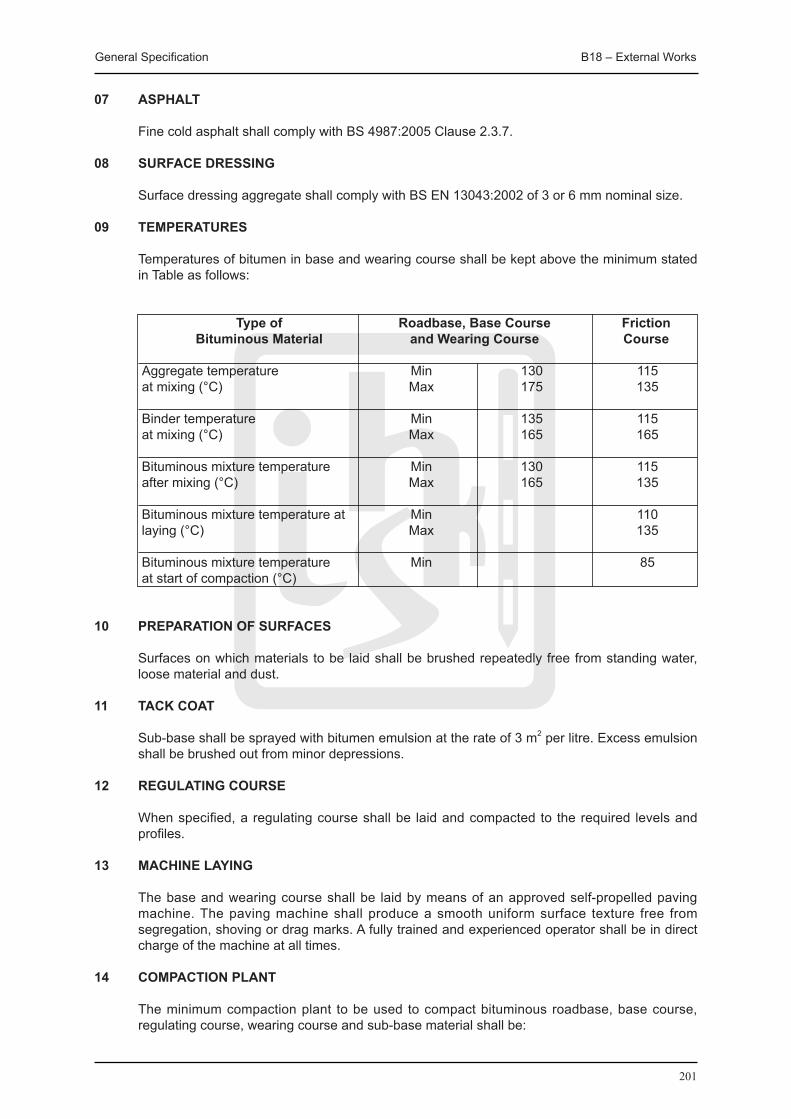
General Specification B18 – External Works
201
07 ASPHALT
Fine cold asphalt shall comply with BS 4987:2005 Clause 2.3.7.
08 SURFACE DRESSING
Surface dressing aggregate shall comply with BS EN 13043:2002 of 3 or 6 mm nominal size.
09 TEMPERATURES
Temperatures of bitumen in base and wearing course shall be kept above the minimum stated in Table as follows:
Type of Roadbase, Base Course Friction Bituminous Material and Wearing Course Course
Aggregate temperature Min 130 115 at mixing (°C) Max 175 135 Binder temperature Min 135 115 at mixing (°C) Max 165 165
Bituminous mixture temperature Min 130 115 after mixing (°C) Max 165 135
Bituminous mixture temperature at Min 110 laying (°C) Max 135
Bituminous mixture temperature Min 85 at start of compaction (°C)
10 PREPARATION OF SURFACES
Surfaces on which materials to be laid shall be brushed repeatedly free from standing water, loose material and dust.
11 TACK COAT Sub-base shall be sprayed with bitumen emulsion at the rate of 3 m2 per litre. Excess emulsion
shall be brushed out from minor depressions.
12 REGULATING COURSE
When specified, a regulating course shall be laid and compacted to the required levels and profiles.
13 MACHINE LAYING
The base and wearing course shall be laid by means of an approved self-propelled paving machine. The paving machine shall produce a smooth uniform surface texture free from segregation, shoving or drag marks. A fully trained and experienced operator shall be in direct charge of the machine at all times.
14 COMPACTION PLANT
The minimum compaction plant to be used to compact bituminous roadbase, base course, regulating course, wearing course and sub-base material shall be:

General Specification B18 – External Works
202
(i) A smooth three-wheeled steel-wheeled roller with a mass of between 6 tonne and 12 tonne, or a vibrating tandem steel-wheeled roller with an effective mass of between 6 tonne and 12 tonne, and a smooth pneumatic-tyred roller with a mass of between 12 tonne and 25 tonne, and with not less than seven overlapping wheels which have tyres that are capable of having pressures varying between 300 MPa and 800 MPa, and suitable mechanical rammers and hand-tools.
(ii) Other types of rollers, vibrating plants and rammers approved by the Contract Administrator, or other similar plant approved by the Contract Administrator, necessary to produce the required degree of compaction.
15 COMPACTION
Compaction shall be commenced as soon as the material will bear the weight of the roller. Roll in a longitudinal direction only, each successive pass overlapping the last by at least a half-width of the rear roller. Rollers shall not stand on newly laid material. Compact the base and wearing course so that air voids in the mixture are between 3 and 5% when measured.
16 HAND LAYING AND CONSOLIDATION
Hand operated mechanical compaction plant laying and consolidation by means of an approved mechanical tamper shall be permitted for work executed in patching-in repairs, reinstating surfaces over excavated trenches, surfacing areas inaccessible to the paving machine or roller, and surfacing areas which in the opinion of the Contract Administrator, are too small to warrant the use of a paving machine and roller.
17 WET WEATHER
Laying bituminous surfacings during wet weather shall be avoided. Laying during heavy rains or when free-standing water is present on surfaces to be coated shall not be allowed.
18 jOINTING
(i) The screed of the paving machine shall overlap previously laid strips of bituminous material by at least 50 mm and shall be sufficiently high that compaction shall produce a smooth dense flush joint. Bituminous materials overlapping the previously laid strip shall be pushed back to the edge of the previously laid strip and the excess material shall be removed.
(ii) Longitudinal joints in friction course or wearing course shall be formed coincident with the specified position of the lane-markings unless otherwise permitted by the Contract Administrator.
(iii) A prepared joint shall be formed between hot bituminous material and cold material or existing bituminous material which is at a temperature below the minimum specified laying temperature.
(iv) The distance between prepared longitudinal joints in different layers shall be at least 150 mm, and the distance between prepared transverse joints in different layers shall be at least 500 mm.
(v) Prepared joints in base course and wearing course shall be formed by cutting back the face of the cold material or existing bituminous material for a minimum distance of twice the depth of the layer or 100 mm, whichever is greater; a vertical face shall be cut for the full depth of the layer. All loosened materials shall be removed and the face shall be coated with bituminous emulsion; the bituminous emulsion shall not be applied beyond the edges of the joint. The hot bituminous materials shall be laid and compacted against the coated face with a joint formed as stated in this clause.
(vi) Unless otherwise permitted by the Contract Administrator friction course joints shall not be coated with bituminous emulsion.

General Specification B18 – External Works
203
19 ACCURACY
The level of each pavement course shall be determined from the surface of the wearing course calculated from the levels, sections, falls and cross falls shown on the drawings and the specified thickness of each course subject to the tolerances stated in Table as follows, but in no circumstances is the nominal thickness of the wearing coat to be reduced by more than 5 mm.
The maximum deviation permitted in surfaces shall be 6 mm from a 3000 mm straight edge.
Tolerances in level of formation and pavement courses (mm):
Type of surface Permitted tolerance in level (mm)
Sub-base +10 -20 Roadbase course +8 -15 Base course Wearing course +6 Friction course
20 CONSTRUCTION
Various pavement courses shall be kept free from deleterious material at all times. No vehicular traffic shall be permitted on wearing courses or surfaces treated with bituminous material until 6 hours after the initial laying.
21 COLD ASPHALT
Tack coat shall be applied, laid by hand and consolidated as specified.
22 SURFACE DRESSING EXISTING AREAS
Existing areas shall be thoroughly dried and swept completely clean of all loose materials, bitumen or bitumen emulsion at the rate of 3 m2 per litre shall be applied evenly by spray or brush as directed. Immediately after the bitumen has been applied, a layer of 3 mm or 6 mm dry granite chipping shall be spread over the surface and rolled in until thoroughly embedded in the bitumen to obtain a uniform compact surface. Approximately one week later, the area shall be swept clear of all loose chipping and removed from Site.
23 CLEANING OFF
After surfacing or dressing has been executed, all channels, kerbs, manhole covers, gratings, etc. shall be cleared and cleaned free of all excess materials and bitumen.
B18.2 EXTERNAL SERVICES
01 CABLE DUCTS
Cable ducts shall be constructed generally in accordance with Section B18 on Drainage in this Specification.
Pipes which form multiple cable ducts shall be spaced 100 mm (minimum) apart. One 6 mm diameter nylon draw cord shall be left in position in each length of duct.
02 DRAW IN PITS
Temporary draw in pits shall be formed and backfilled with clean sand and provided with 50x50x600 mm long timber location marker. Draw-in pits shall be constructed in accordance with drawings.
General Specification B18 – External Works
204
03 RECORD DRAWINGS
All information required by the Contract Administrator shall be provided for preparation of record drawings.
B18.3 FENCING AND GATES
B18.3.1 MATERIALS
01 FENCING WIRE
Steel wire for fencing, including chain link and barbed wire shall comply with BS 4102:1998. (i) Galvanised steel wire. (ii) Grade A - Plastic coated galvanised steel wire. (iii) Grade B - Plastic coated steel wire.
Galvanised wire netting shall comply with BS EN 10223-2:1998, or of approved local manufacture.
02 STEEL FENCE POSTS AND GATES
Steel fence posts and gates shall be constructed in accordance with Metalwork.
B18.3.2 WORKMANSHIP
01 FENCING GENERALLY
Fencing shall be erected to the lines and levels indicated on the drawings. Fencing shall be erected to a smooth alignment with no abrupt irregularities. The ground shall be trimmed or filled in such a manner that the bottom of the fence will approximately follow the level of the ground. The distance between the bottom of chain link mesh and hoarding and the ground shall not exceed 100 mm.
02 FENCING WIRE
Line wire, chain link mesh and barbed wire for fencing shall be strained tightly between straining posts. Winding brackets shall be used for straining between steel posts. The tension in the wire on each side of straining posts shall be equal. Wire shall be strained until at least 14 days after concrete has been placed in the foundation.

205
B19 SundryItems

General Specification B19 – Sundry Items
206
B19 SUNDRY ITEMS
B19.1 FIXINGS / ADHESIVES
01 FIXING
Suitable fixing and jointing methods and types, sizes, quantities and spacings of fastenings having regard to the following shall be used:
(i) Nature of and compatibility with product/material being fixed and fixed to, (ii) Recommendations of manufacturers of fastenings and manufacturers of components,
products or materials being fixed and fixed to, (iii) Materials and loads to be supported, (iv) Conditions expected in use, (v) Appearance, this being subject to approval.
02 FASTENINGS
Fastenings for materials and components forming part of external construction shall be of corrosion resistant material or shall have a corrosion resistant finish.
03 FIXING THROUGH FINISHES
Fastenings and plugs (if used) shall have ample penetration into the backing.
04 CRAMP FIXING
Cramps shall be fixed with stainless or galvanized steel strip complying with BS EN 845-1:2003+A1:2008 vertical twist ties except with no twist, split one end only and once bent.
Cramps shall be positioned 150 mm from each end of jambs and at 600 mm maximum centres.
Cramps shall be secured to frames with two sherardized screws and fully bed in mortar.
05 PELLETING
Screw heads shall be countersunk 6 mm below timber surface and grain-matched pellets cut from matching timber shall be glued in. Surface shall be finished off flush with face.
06 ADHESIVES
Types: As specified in the relevant section. Surfaces to receive adhesive shall be sound, unfrozen and free from contamination likely to
affect bond. Where necessary, surfaces shall be cleaned as recommended by manufacturer. Surfaces shall be of sufficient smoothness and evenness to suit gap filling and bonding
characteristics of adhesive. Manufacturer’s and statutory requirements for storage and safe usage of adhesives shall be
observed. Adhesive shall not be used in unsuitable environments or beyond the manufacturer’s
recommended time period. Adhesive shall be applied by using recommended spreaders/applicators to ensure correct
coverage. Surfaces shall be brought together within recommended time period with pressure applied to ensure full bonding.
Surplus adhesive shall be removed by using methods recommended by manufacturer, without
damage to affected surfaces.
General Specification B19 – Sundry Items
207
B19.2 MORTARS
01 MORTAR MIX PROPORTIONS Mortar mix proportions and other particular requirements are specified elsewhere. 02 SAND FOR MORTAR
Sand and mortar shall comply with BS EN 13139:2002 unless specified otherwise. Sand for facework mortar shall be from one source, different loads to be mixed if necessary to
ensure consistency of colour and texture. When a range is specified (e.g. 1:1:5-6) lower proportion of sand for Grade G sands and higher
proportion for Grade S shall be used.
03 READY-MIXED LIME:SAND
Unless specified otherwise, ready-mixed lime:sand complying with BS EN 998-2:2003, BS EN 998-1:2003 shall be used. Coloured mortar, where required, shall be made using a proprietary coloured ready-mixed lime:sand, with colour to approval where not specified.
04 SITE PREPARED LIME:SAND MIX
Ready prepared lime putty complying with BS EN 459-1:2001 shall be thoroughly mixed with sand, stored in airtight bins and prevented from drying out. Before gauging with other constituents the mix shall be thoroughly rammed, beaten and chopped.
05 CEMENT FOR MORTAR
When not specified otherwise, cement shall be Portland cement or Portland blastfurnace cement, complying with class 42.5 or 52.5, manufactured and supplied under the BSI Kitemark scheme for cement. All cements shall comply with the appropriate British Standard.
06 ADMIXTURES: To BS EN 934-3:2003
Admixture shall not be used in mortar unless specified or approved. Calcium chloride or any admixtures containing calcium chloride shall be used.
07 MAKING MORTAR
Materials shall be measured accurately by volume using clean gauge boxes. Proportions of mixes are for dry sand; bulking shall be allowed for if sand is damp.
Ingredients shall be mixed thoroughly to a consistence suitable for the work and free from
lumps. Mortars containing air entraining admixtures shall not be over-mixed. Mortar shall not be mixed when the air temperature is at or below 3 oC. Mortar shall be used within about two hours of mixing at normal temperatures.
Mortar shall not be used after the initial set has taken place and retemper mortar is not allowed. Plant and banker boards shall be kept clean at all times.
General Specification B19 – Sundry Items
208
B19.3 SEALANTS
01 SUITABILITY OF jOINTS
Before commencement of works, the following shall be checked: (i) Joint dimensions are within limits specified for the sealant. (ii) Surfaces are smooth and undamaged. (iii) Preparatory work which shall be done before assembly of the joint has been carried out. Contract Administrator shall be informed if joints are not suitable to receive sealant and
proposals for rectification shall be submitted.
02 PREPARING jOINTS
All temporary coatings, tapes, loosely adhering material, dust, oil, grease and other contaminants which may affect bond shall be removed.
Backing strip, bond breaker, primer of types recommended for the purpose by sealant
manufacturer shall be used. Backing strips and/or bond breaker tape shall be inserted into joint leaving no gaps. Adjacent surfaces shall be covered with masking tape to prevent staining and surfaces which
would be difficult to clean if smeared with primer or sealant shall be protected.
03 APPLYING SEALANTS
Sealants shall not be applied to damp surfaces (unless recommended otherwise), to surfaces affected by ice or snow or during inclement weather. Joints shall not be heated to dry or to raise the temperature.
Joints shall be filled completely, leaving no gaps, excluding all air and ensuring firm adhesion
of sealant to required joint surfaces. Sealant shall be tooled to a neat, slightly concave profile unless specified otherwise.
B19.4 POWDER COATINGS
01 POWDER COATING MATERIALS
They shall be obtained from the selected manufacturers. The Contract Administrator shall be informed of selected manufacturer at an early date.
02 WORKING PROCEDURES
Unless specified otherwise, all relevant requirements and recommendations of the following standards shall be complied with:
(i) BS 6496:1984 for aluminium alloy backgrounds. (ii) BS EN 13438:2005 for galvanized steel backgrounds. (iii) British Coatings Federation: Code of safe practice - Application of powder coatings by
electrostatic spraying. 03 APPLICATOR REqUIREMENTS
Powder coatings shall be applied by an applicator approved by the powder coating manufacturer. Evidence of approval shall be provided to the Contract Administrator on request.
Only one plant of the applicator shall be used wherever practical. The applicator shall comply with all quality procedures, standards and tests required by the
powder coating manufacturer.

General Specification B19 – Sundry Items
209
The applicator shall issue a certificate to the Contract Administrator on request and before delivery of work to site, confirming that coatings are in accordance with this specification.
Copies of the powder coating manufacturer’s and/or applicator’s guarantees shall be issued to the Contract Administrator on completion of work.
04 CONTROL SAMPLES
Prior to ordering materials for the works, approval for the following shall be obtained: Uncoated and powder coated samples of the various grades and forms of background metal to
be used.
Fabrication samples showing joint assembly, how powder coating is affected and how any cut metal edges are protected.
05 TESTING
Independent acceptance testing of powder coatings will be commissioned by the Contract Administrator in the event of any deficiency in tested production samples or in finished components. Production samples for testing and/or safe access for site testing shall be provided when requested by the Contract Administrator.
06 COMPONENT DESIGN
Components to be powder coated shall comply with relevant recommendations of BS 4479:Parts 1,3,4, and 6:1990, and are of suitable size to fit plant capacity and of suitable thickness to withstand oven curing.
Deflection under design load or thermal movement of background metal of components shall
not be detrimental to powder coatings.
07 PRETREATMENT
All components to be powder coated shall be free from corrosion and damage, and suitable for and compatible with the pretreatment and powder coating process.
All components shall be cleaned, conversion coated, conditioned, drained and dried in
accordance with the powder coating manufacturer’s requirements and the pretreatment supplier’s recommendations.
08 EXTENT OF POWDER COATINGS
Approval of drawn proposals or schedules for component surfaces to receive powder coatings shall be obtained.
All approved surfaces shall be deemed ‘significant surfaces’ for relevant BS 6496:1984/BS
6497:1984, performance requirements.
09 APPEARANCE OF POWDER COATINGS
The quality of finish must be consistent and in accordance with BS 6496:1984/BS 6497:1984, clause 10.2. A slight degree of ‘orange peel’ texture may be acceptable, subject to approval of the Contract Administrator and the powder coating manufacturer.
The gloss level of finish shall be consistent and when tested in accordance with BS 6496:1984/
BS 6497:1984, clause 4.3 shall be within the relevant range given in the powder coating manufacturer’s literature.
General Specification B19 – Sundry Items
210
10 ALUMINIUM ALLOY FABRICATIONS
Units may be assembled:
(i) Before powder coating. (ii) From components powder coated after cutting to size. (iii) From components powder coated before cutting to size, subject to approval of the
Contract Administrator and the powder coating manufacturer. Assembly of components resulting in exposure of background metal shall not be accepted.
11 STEEL FABRICATIONS
Wherever practical units shall be assembled before powder coating.
12 FIXINGS
All exposed metal fixings shall be powder coated together with components, or coated with matching repair paint system applied in accordance with the powder coating manufacturer’s recommendations.
13 FABRICATION DAMAGE REPAIR / REPLACEMENT
All components shall be checked before delivery to site for powder coating damage. Findings and proposed method of repair or replacement shall be reported to the Contract Administrator and approval shall be obtained before commencing remedial work.
Components with minor damage shall be repaired as soon as possible by cleaning, abrading
and coating with matching repair paint system applied in accordance with the powder coating manufacturer’s recommendations.
Components with major damage considered unacceptable for repair shall be replaced.
Stripping and recoating of components shall only be acceptable by prior agreement of the powder coating manufacturer. Stripping, pretreatment and powder coating shall be in accordance with manufacturer’s requirements.
Overcoating of components shall not be acceptable.
14 PROTECTION
All powder coated surfaces of components vulnerable to damage during handling and installation, or by subsequent site operations, shall be fully protected throughout the course of these works.
Protective coverings shall be resistant to all weathers, removable from areas inaccessible
after installation, and partially removable and replaceable for access to fixing points during installation or subsequent site operations.
Any protective tapes used in direct contact with powder coatings shall be low tack, self
adhesive type and light in colour. Their use for application to powder coatings shall be approved by the tape manufacturer, and shall be applied and removed in accordance with the tape manufacturer’s requirements and the powder coating manufacturer’s recommendations.
Monthly inspections of protective coverings shall be carried out and any deterioration or
deficiency shall be promptly repaired. Protective coverings shall be removed only when instructed by the Contract Administrator.
General Specification B19 – Sundry Items
211
15 PROTECTION MOCK-UPS
Protection mock-ups in similar exposure conditions to their proposed installation shall be erected and inspection procedures shall be agreed with the Contract Administrator.
16 SITE DAMAGE REPAIR / REPLACEMENT
Any damage to powder coatings caused during handling and installation, or by subsequent site operations, shall be rectified immediately. Approval shall be obtained before commencing extensive repairs or replacements.
Components with minor damage shall be repaired by cleaning, abrading and coating with
matching repair paint system applied in accordance with the powder coating manufacturer’s recommendations.
Components with major damage considered unacceptable for repair shall be repaired.
17 MAINTENANCE
After removal of protective coverings, all powder coated surfaces shall be cleaned and maintained at regular intervals until Practical Completion. All maintenance shall be in accordance with procedures detailed in the powder coating manufacturer’s technical literature and the guarantee.
B19.5 REPLACEMENT OF EXPANSION jOINT SEALANT
Expansion joint shall be repaired strictly in accordance with the following specification: - (i) Thoroughly rake out and cart away existing backing rod/joint filler and sealant of
expansion joints in wall (one or both sides of the wall where appropriate). (ii) Carefully saw-cut, take down and remove defective wall tiles/mortar or internal plaster on
both sides of the expansion joint and fix new wall tiles or plaster and finished to flush with existing wall surfaces to match.
(iii) All cracks, spalling and other defect of expansion joint should be rectified by approved method and material before installation of new materials for expansion joints.
(iv) Concrete surface of expansion joints shall be smooth and primed and must be dry, free of debris, dust, dirt, grease, oil and other contaminants.
(v) Clean the joint surface by mechanical grinding followed by a high air pressure blasting. (vi) Clean the joint surfaces again with approved degreasing solvent. (vii) Place backing rod/joint filler at the required depth and place masking tape to both sides of
joint to assure neat sealant line. (viii) Installation of new silicone building sealant at a width to depth ratio of 2:1 to the joint or
strictly in accordance with the manufacturer’s recommendation. (ix) Tool the installed sealant with light pressure to spread the material against the back-up
material and the joint surface.
The sealant for expansion joints repair shall be approved by Contract Administrator.
The colour of new applied expansion joint shall match with the surroundings or be subject to the approval of Contract Administrator. The contractor shall submit sample of sealant of expansion joint, backing rod, joint filler and primer to the Contract Administrator for approval in advance of work commencement.
The contractor shall upon instruction by the Contract Administrator carry out random follow-up inspection as a final check for adhesion of the installed sealant. A hand pull test shall be carried out on site after the sealant is fully cured (approx. 7-14 days). The hand pull test procedures shall be as follows:
(i) Make a knife cut horizontally across the joint. (ii) Make two vertical cuts approximately 50 mm long at the sides of the joint, meeting the
horizontal cut at the top of two 50 mm cuts. (iii) Grasp the 50 mm piece of sealant firmly between the fingers and pull down at 90 degree

General Specification B19 – Sundry Items
212
angle or more, and try to pull the uncut sealant out of the joint. (iv) If adhesion is acceptable, the sealant should tear cohesively in itself before releasing
adhesively from the substrate. (v) Sealant cut in adhesion test is to be replaced by applying sealant in the same manner as
originally installed.
B19.6 SEEDING/TURFING
01 TOPSOIL
At the time of starting the work, the areas to be seeded/turfed shall be covered by topsoil. Undisturbed topsoil shall be prepared as necessary by the Main Contractor so that it is in a
suitable state for the cultivation operations specified in this section.
02 CLIMATIC CONDITIONS
Work shall be carried out during appropriate seasons and while soil and weather conditions are suitable for the relevant operations.
03 MACHINES AND TOOLS
Only machinery and tools suitable for the site conditions and the work to be carried out shall be used. Hand tools shall be used around trees, plants and in confined spaces where it is impracticable to use machinery.
04 WATER
It shall be provided by the Main Contractor up to Practical Completion of the Main Contract Works and/or thereafter by the Employer, in each case subject to availability of supply.
05 DROUGHT CONDITIONS
If water supply is or is likely to be restricted by emergency legislation: (i) Contract Administrator shall be informed without delay and availability and additional
cost of second class water from a sewage works or other approved source shall be ascertained.
(ii) If seeding/turfing has not been carried out, do not do so until instructed. (iii) If seeding/turfing has been carried out, obtain instructions on supply of water.
06 NOTICE TO CONTRACT ADMINISTRATOR
Advance arrangements shall be made with Contract Administrator to give him the opportunity of being present during:
(i) Setting out (ii) Application of weedkiller (iii) Application of fertilizer (iv) Seeding or turfing (v) Planting of shrubs (vi) Planting of trees into previously dug pits (vii) Each site visit during maintenance period.
07 SETTING OUT
Boundaries of seeding/turfing areas shall be clearly marked and approval shall be obtained before starting work.
08 CHEMICALS
Chemicals shall be used only where specified or approved, and shall be products on the
General Specification B19 – Sundry Items
213
current list of the Agricultural Chemicals Approval Scheme.
Where work is near water, drainage ditches or land drains, ‘Code of Practice for the use of herbicides on weeds in water courses and lakes’ shall be complied with.
All precautions recommended by the manufacturer shall be observed and containers shall be removed from site immediately after emptied or are no longer required.
09 HERBICIDE
Herbicide shall be of a type recommended for the purpose in the current list of the Agricultural Chemicals Approval Scheme.
Herbicide shall be applied to perennial weeds and period of time shall be allowed to elapse as
recommended by manufacturer before cultivation.
10 SAND
Sand shall be coarse grained, washed river sand with neutral pH.
11 PEAT
Spagnum peat shall comply with BS EN 12579:2000, BS EN 13038:2000, BS EN 13039:2000, BS EN 13041:2000. No alkaline peat shall be used unless instructed.
12 COMPOST
Sewage sludge: Dewatered solid sludge cake with a maximum moisture content of 10% and containing not less than 6% nitrogen, 3% phosphate, 5% potash.
Manure: Well rotted horse or farmyard dung but not poultry or pig manure.
Mushroom compost: Spent mushroom beds containing only well rotted manure, peat, chalk and residual mushroom growth.
Leaf mould: Well rotted broad leaves from deciduous trees but not ash, poplar or sycamore leaves.
Other well rotted organic material subject to approval.
13 CULTIVATION
Any compacted topsoil to full depth shall be broken up.
Top 100 mm of all topsoil shall be reduced to a tilth suitable for blade grading (10 mm down particles).
Undesirable material brought to the surface including stones and clay balls larger than 50 mm in any dimension, roots, tufts of grass and foreign matter shall be removed.
14 GRADING
When topsoil is reasonably dry and workable, it shall be graded to smooth, flowing contours, with falls for adequate drainage, removing all minor hollows and ridges.
Unless otherwise stated, finished levels after settlement shall be 30 mm above adjoining paving, kerbs, manholes etc.

General Specification B19 – Sundry Items
214
15 FERTILIZER
Three to five days before seeding/turfing and before final cultivation both the following fertilizers, each at 70g/sq m, in transverse directions shall be applied:
Superphosphate with a minimum of 18% water soluble phosphoric acid.
A sulphate of ammonia with a minimum of 20% nitrogen.
16 FINAL CULTIVATION
After grading and fertilizing, further cultivation shall be carried out to reduce top 25 mm to a fine tilth.
Surface shall be raked to a true, even, lightly firmed, removing all stones and clay balls more than 50 mm in any dimension on general areas and 25 mm on fine lawns.
Cultivation shall be extended into any adjacent existing grass areas to ensure full marrying in of levels.
Approval of appearance of prepared soil areas shall be obtained before seeding/turfing.
B19.7 SEEDING
01 qUALITY OF SEED
Fresh seed for each growing season shall be purchased and seed purchased for previous seasons shall not be used.
Germination capacity: Not less than 80% Purity of mixture: Not less than 90% Total weed seed content: Not more than 0.5% Total content of other crop seeds: Not more than 1%.
When requested, results of testing for germination, purity and composition carried out by an Official Seed Testing Station shall be submitted.
02 SOWING
Seed shall be spreaded evenly at the specified rate(s) applied in two equal sowings in transverse directions, lightly harrowed or raked and on light soils rolled and cross rolled after seeding using a lightweight roller.
03 PRE-EMERGENT HERBICIDE
Where soil has not been allowed to lie fallow, a suitable pre-emergent herbicide shall be applied immediately after sowing.
04 TURF EDGING TO SEEDED AREAS
Before sowing, a 300 mm wide margin around prepared seed beds where shown on drawings shall be raked back.
A single row of turves (complying with BS 3969:1998 with no ryegrass) shall be laid end to end and trimmed to a line.
Level of seed bed shall be married in with the turf and turf shall be watered on completion.
05 HYDRAULIC SEEDING
A proprietary seeding system suitable for the location and conditions, including all necessary
General Specification B19 – Sundry Items
215
preparation and ancillary work, shall be carried out by an approved specialist subcontractor.
Hardcore and stones exceeding 100 mm in any dimension and all rubbish shall be removed.
All pernicious weeds shall be killed using a selective hormone weedkiller and other weeds shall be killed using a contact selective weedkiller.
Surface shall be smoothened by filling depressions and ruts and levelling ridges to avoid sudden changes in level of more than 100 mm.
Basic cultivation shall be carried out as much as possible to ensure that the roots can penetrate into the substrate, and fertilizer as recommended by the subcontractor shall be applied.
The grass shall be cut when well established and approximately 75 mm of growth shall be left. Arisings shall be spread evenly over the cut areas.
B19.8 TURFING
01 STORAGE
Supply of turves shall be arranged to avoid stacking for more than three days.
Storage shall not be stacked to a height of more than 1 m.
Turves which show any signs of deterioration shall be used without delay or laid out on topsoil and kept moist.
02 TURFING GENERALLY
Turf shall be laid during autumn or early winter or at times agreed with Contract Administrator.
Turf shall not be laid when persistent cold or drying winds are likely to occur or soil is frost bound, waterlogged or excessively dry.
Turf shall be laid with broken joints, well butted up, working from planks laid on previously laid turves.
Whole turves at edges shall be used and trimmed to a true line.
Levels shall be adjusted by raking out or infilling with fine soil under turves.
Turf shall be consolidated by lightly and evenly firming with wooden beaters as the laying proceeds. Rollers shall not be used.
Turf shall be dressed with finely sifted topsoil/peat/sand and brushed well in to completely fill all joints.
The completed turf shall be watered thoroughly within 24 hours of laying.
03 BANKS EXCEEDING 30 DEGREES SLOPE
Turves shall be laid diagonally or horizontally and secured with either: (i) pointed softwood pegs, 200 mm long x 25 mm square, or (ii) galvanised wire pins, bent or hairpin pattern, 200 mm long x 4 mm diameter. All pegs or pins shall be removed when turf is well established.
04 NEWLY PLANTED TREES
Turf shall be neatly cut away to a diameter of 800 mm around individual trees and leave open.
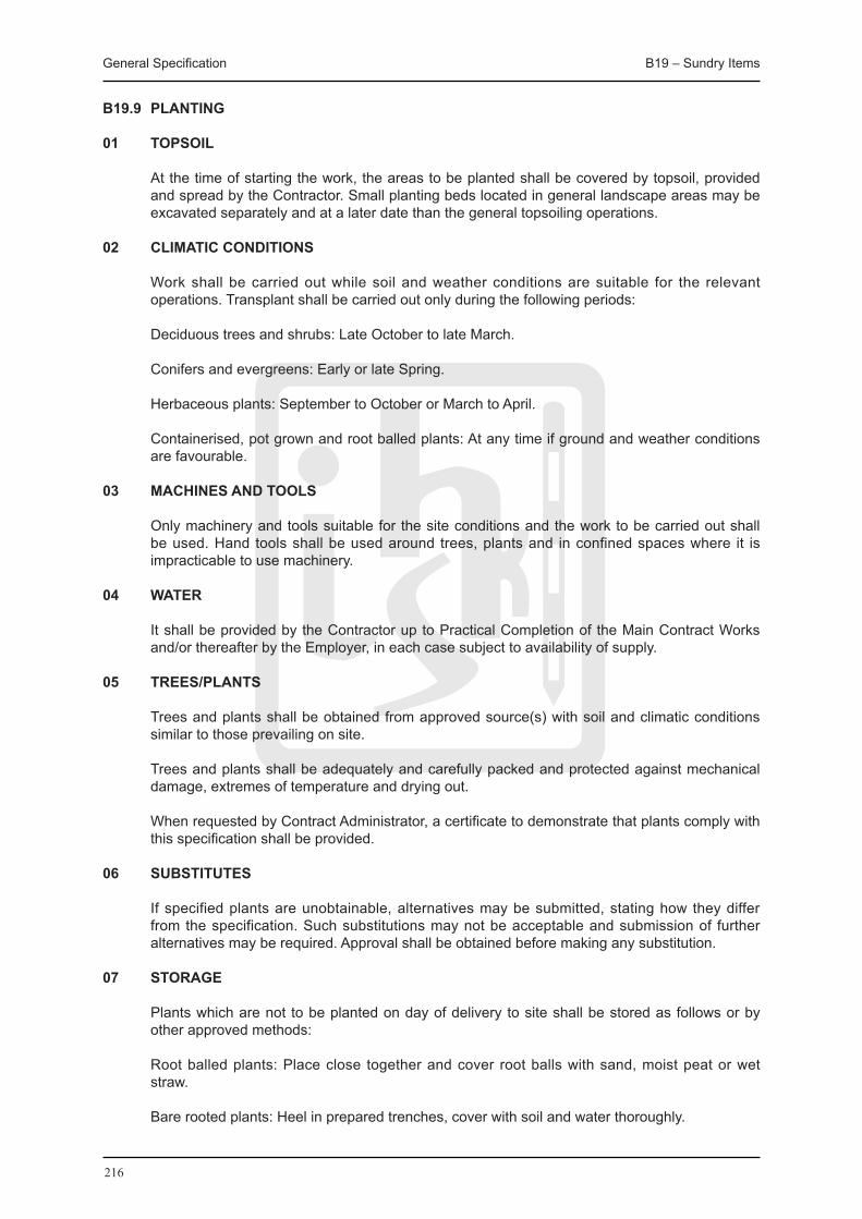
General Specification B19 – Sundry Items
216
B19.9 PLANTING
01 TOPSOIL
At the time of starting the work, the areas to be planted shall be covered by topsoil, provided and spread by the Contractor. Small planting beds located in general landscape areas may be excavated separately and at a later date than the general topsoiling operations.
02 CLIMATIC CONDITIONS
Work shall be carried out while soil and weather conditions are suitable for the relevant operations. Transplant shall be carried out only during the following periods:
Deciduous trees and shrubs: Late October to late March.
Conifers and evergreens: Early or late Spring.
Herbaceous plants: September to October or March to April.
Containerised, pot grown and root balled plants: At any time if ground and weather conditions are favourable.
03 MACHINES AND TOOLS
Only machinery and tools suitable for the site conditions and the work to be carried out shall be used. Hand tools shall be used around trees, plants and in confined spaces where it is impracticable to use machinery.
04 WATER
It shall be provided by the Contractor up to Practical Completion of the Main Contract Works and/or thereafter by the Employer, in each case subject to availability of supply.
05 TREES/PLANTS
Trees and plants shall be obtained from approved source(s) with soil and climatic conditions similar to those prevailing on site.
Trees and plants shall be adequately and carefully packed and protected against mechanical damage, extremes of temperature and drying out.
When requested by Contract Administrator, a certificate to demonstrate that plants comply with this specification shall be provided.
06 SUBSTITUTES
If specified plants are unobtainable, alternatives may be submitted, stating how they differ from the specification. Such substitutions may not be acceptable and submission of further alternatives may be required. Approval shall be obtained before making any substitution.
07 STORAGE
Plants which are not to be planted on day of delivery to site shall be stored as follows or by other approved methods:
Root balled plants: Place close together and cover root balls with sand, moist peat or wet straw.
Bare rooted plants: Heel in prepared trenches, cover with soil and water thoroughly.
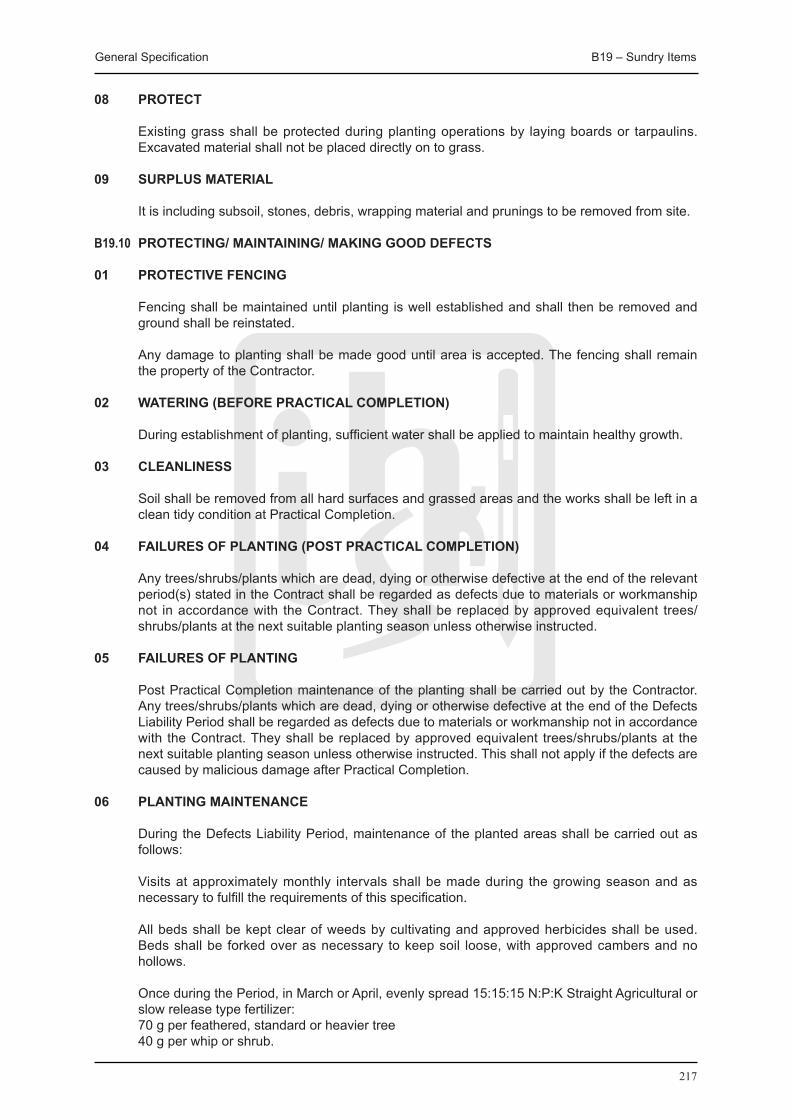
General Specification B19 – Sundry Items
217
08 PROTECT
Existing grass shall be protected during planting operations by laying boards or tarpaulins. Excavated material shall not be placed directly on to grass.
09 SURPLUS MATERIAL
It is including subsoil, stones, debris, wrapping material and prunings to be removed from site.
B19.10 PROTECTING/ MAINTAINING/ MAKING GOOD DEFECTS
01 PROTECTIVE FENCING
Fencing shall be maintained until planting is well established and shall then be removed and ground shall be reinstated.
Any damage to planting shall be made good until area is accepted. The fencing shall remain the property of the Contractor.
02 WATERING (BEFORE PRACTICAL COMPLETION)
During establishment of planting, sufficient water shall be applied to maintain healthy growth.
03 CLEANLINESS
Soil shall be removed from all hard surfaces and grassed areas and the works shall be left in a clean tidy condition at Practical Completion.
04 FAILURES OF PLANTING (POST PRACTICAL COMPLETION)
Any trees/shrubs/plants which are dead, dying or otherwise defective at the end of the relevant period(s) stated in the Contract shall be regarded as defects due to materials or workmanship not in accordance with the Contract. They shall be replaced by approved equivalent trees/shrubs/plants at the next suitable planting season unless otherwise instructed.
05 FAILURES OF PLANTING
Post Practical Completion maintenance of the planting shall be carried out by the Contractor. Any trees/shrubs/plants which are dead, dying or otherwise defective at the end of the Defects Liability Period shall be regarded as defects due to materials or workmanship not in accordance with the Contract. They shall be replaced by approved equivalent trees/shrubs/plants at the next suitable planting season unless otherwise instructed. This shall not apply if the defects are caused by malicious damage after Practical Completion.
06 PLANTING MAINTENANCE
During the Defects Liability Period, maintenance of the planted areas shall be carried out as follows:
Visits at approximately monthly intervals shall be made during the growing season and as necessary to fulfill the requirements of this specification.
All beds shall be kept clear of weeds by cultivating and approved herbicides shall be used. Beds shall be forked over as necessary to keep soil loose, with approved cambers and no hollows.
Once during the Period, in March or April, evenly spread 15:15:15 N:P:K Straight Agricultural or slow release type fertilizer:
70 g per feathered, standard or heavier tree 40 g per whip or shrub.
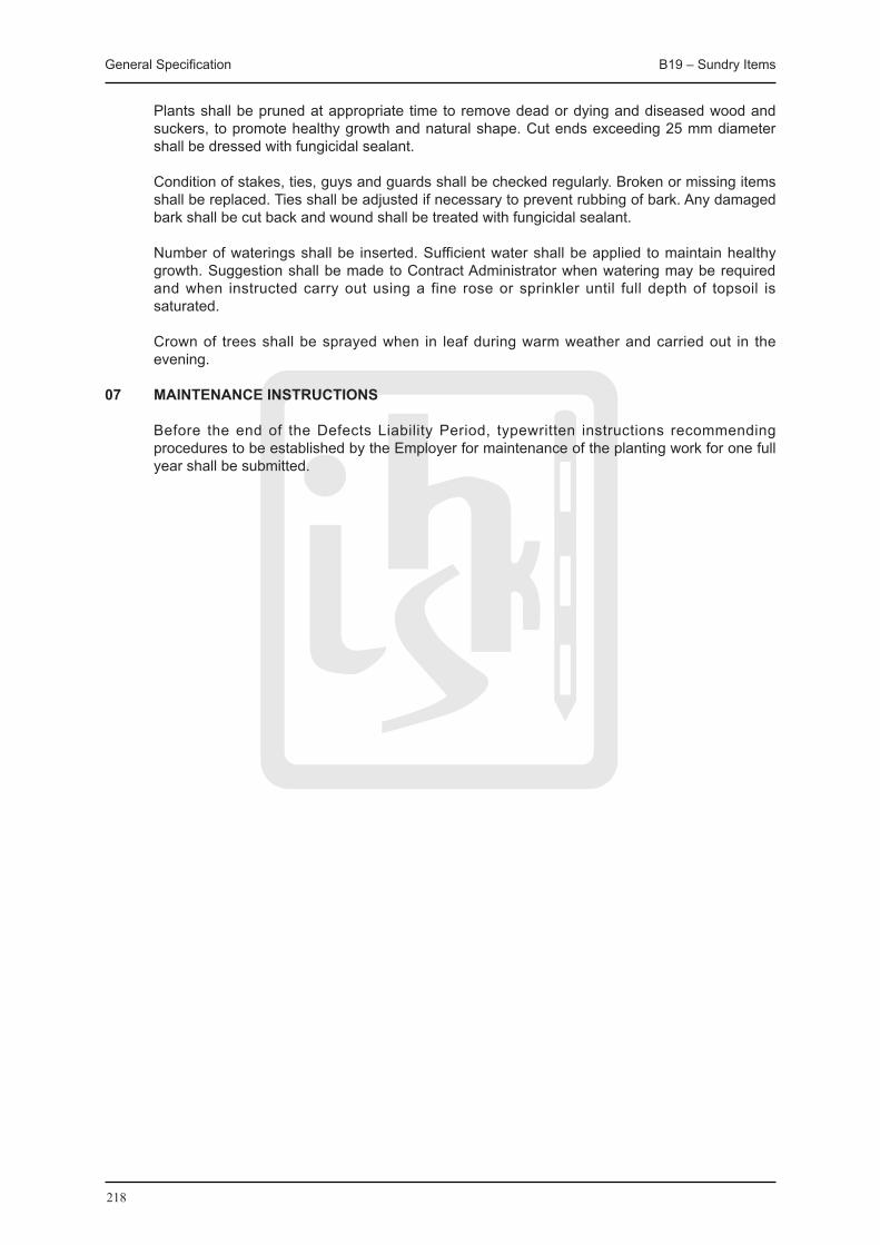
General Specification B19 – Sundry Items
218
Plants shall be pruned at appropriate time to remove dead or dying and diseased wood and suckers, to promote healthy growth and natural shape. Cut ends exceeding 25 mm diameter shall be dressed with fungicidal sealant.
Condition of stakes, ties, guys and guards shall be checked regularly. Broken or missing items shall be replaced. Ties shall be adjusted if necessary to prevent rubbing of bark. Any damaged bark shall be cut back and wound shall be treated with fungicidal sealant.
Number of waterings shall be inserted. Sufficient water shall be applied to maintain healthy growth. Suggestion shall be made to Contract Administrator when watering may be required and when instructed carry out using a fine rose or sprinkler until full depth of topsoil is saturated.
Crown of trees shall be sprayed when in leaf during warm weather and carried out in the evening.
07 MAINTENANCE INSTRUCTIONS
Before the end of the Defects Liability Period, typewritten instructions recommending procedures to be established by the Employer for maintenance of the planting work for one full year shall be submitted.

219
C20 WaterSupplySystem
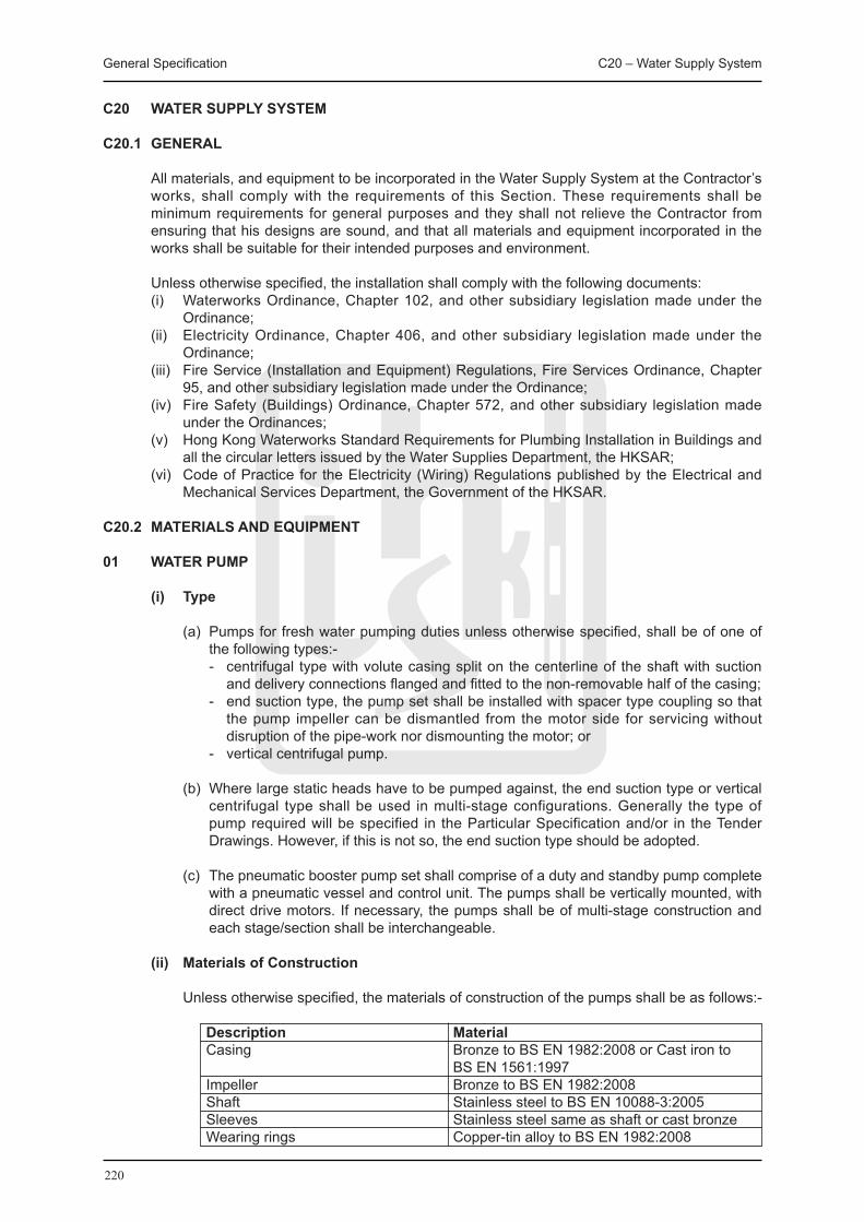
General Specification C20 – Water Supply System
220
C20 WATER SUPPLY SYSTEM
C20.1 GENERAL
All materials, and equipment to be incorporated in the Water Supply System at the Contractor’s works, shall comply with the requirements of this Section. These requirements shall be minimum requirements for general purposes and they shall not relieve the Contractor from ensuring that his designs are sound, and that all materials and equipment incorporated in the works shall be suitable for their intended purposes and environment.
Unless otherwise specified, the installation shall comply with the following documents: (i) Waterworks Ordinance, Chapter 102, and other subsidiary legislation made under the
Ordinance; (ii) Electricity Ordinance, Chapter 406, and other subsidiary legislation made under the
Ordinance; (iii) Fire Service (Installation and Equipment) Regulations, Fire Services Ordinance, Chapter
95, and other subsidiary legislation made under the Ordinance; (iv) Fire Safety (Buildings) Ordinance, Chapter 572, and other subsidiary legislation made
under the Ordinances; (v) Hong Kong Waterworks Standard Requirements for Plumbing Installation in Buildings and
all the circular letters issued by the Water Supplies Department, the HKSAR; (vi) Code of Practice for the Electricity (Wiring) Regulations published by the Electrical and
Mechanical Services Department, the Government of the HKSAR.
C20.2 MATERIALS AND EqUIPMENT
01 WATER PUMP
(i) Type
(a) Pumps for fresh water pumping duties unless otherwise specified, shall be of one of the following types:-
- centrifugal type with volute casing split on the centerline of the shaft with suction and delivery connections flanged and fitted to the non-removable half of the casing;
- end suction type, the pump set shall be installed with spacer type coupling so that the pump impeller can be dismantled from the motor side for servicing without disruption of the pipe-work nor dismounting the motor; or
- vertical centrifugal pump.
(b) Where large static heads have to be pumped against, the end suction type or vertical centrifugal type shall be used in multi-stage configurations. Generally the type of pump required will be specified in the Particular Specification and/or in the Tender Drawings. However, if this is not so, the end suction type should be adopted.
(c) The pneumatic booster pump set shall comprise of a duty and standby pump complete with a pneumatic vessel and control unit. The pumps shall be vertically mounted, with direct drive motors. If necessary, the pumps shall be of multi-stage construction and each stage/section shall be interchangeable.
(ii) Materials of Construction
Unless otherwise specified, the materials of construction of the pumps shall be as follows:-
Description Material Casing Bronze to BS EN 1982:2008 or Cast iron to BS EN 1561:1997 Impeller Bronze to BS EN 1982:2008 Shaft Stainless steel to BS EN 10088-3:2005 Sleeves Stainless steel same as shaft or cast bronze Wearing rings Copper-tin alloy to BS EN 1982:2008
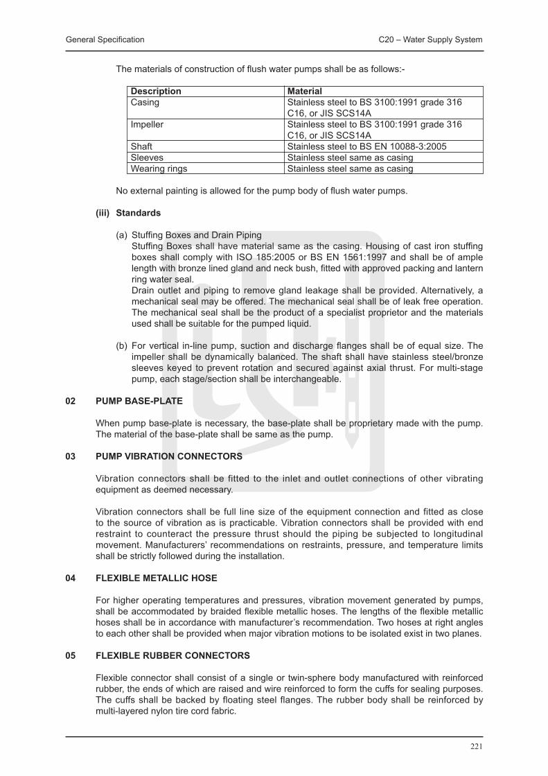
General Specification C20 – Water Supply System
221
The materials of construction of flush water pumps shall be as follows:-
Description Material Casing Stainless steel to BS 3100:1991 grade 316 C16, or JIS SCS14A Impeller Stainless steel to BS 3100:1991 grade 316 C16, or JIS SCS14A Shaft Stainless steel to BS EN 10088-3:2005 Sleeves Stainless steel same as casing Wearing rings Stainless steel same as casing
No external painting is allowed for the pump body of flush water pumps.
(iii) Standards
(a) Stuffing Boxes and Drain Piping Stuffing Boxes shall have material same as the casing. Housing of cast iron stuffing
boxes shall comply with ISO 185:2005 or BS EN 1561:1997 and shall be of ample length with bronze lined gland and neck bush, fitted with approved packing and lantern ring water seal.
Drain outlet and piping to remove gland leakage shall be provided. Alternatively, a mechanical seal may be offered. The mechanical seal shall be of leak free operation. The mechanical seal shall be the product of a specialist proprietor and the materials used shall be suitable for the pumped liquid.
(b) For vertical in-line pump, suction and discharge flanges shall be of equal size. The impeller shall be dynamically balanced. The shaft shall have stainless steel/bronze sleeves keyed to prevent rotation and secured against axial thrust. For multi-stage pump, each stage/section shall be interchangeable.
02 PUMP BASE-PLATE
When pump base-plate is necessary, the base-plate shall be proprietary made with the pump. The material of the base-plate shall be same as the pump.
03 PUMP VIBRATION CONNECTORS
Vibration connectors shall be fitted to the inlet and outlet connections of other vibrating equipment as deemed necessary.
Vibration connectors shall be full line size of the equipment connection and fitted as close to the source of vibration as is practicable. Vibration connectors shall be provided with end restraint to counteract the pressure thrust should the piping be subjected to longitudinal movement. Manufacturers’ recommendations on restraints, pressure, and temperature limits shall be strictly followed during the installation.
04 FLEXIBLE METALLIC HOSE
For higher operating temperatures and pressures, vibration movement generated by pumps, shall be accommodated by braided flexible metallic hoses. The lengths of the flexible metallic hoses shall be in accordance with manufacturer’s recommendation. Two hoses at right angles to each other shall be provided when major vibration motions to be isolated exist in two planes.
05 FLEXIBLE RUBBER CONNECTORS
Flexible connector shall consist of a single or twin-sphere body manufactured with reinforced rubber, the ends of which are raised and wire reinforced to form the cuffs for sealing purposes. The cuffs shall be backed by floating steel flanges. The rubber body shall be reinforced by multi-layered nylon tire cord fabric.
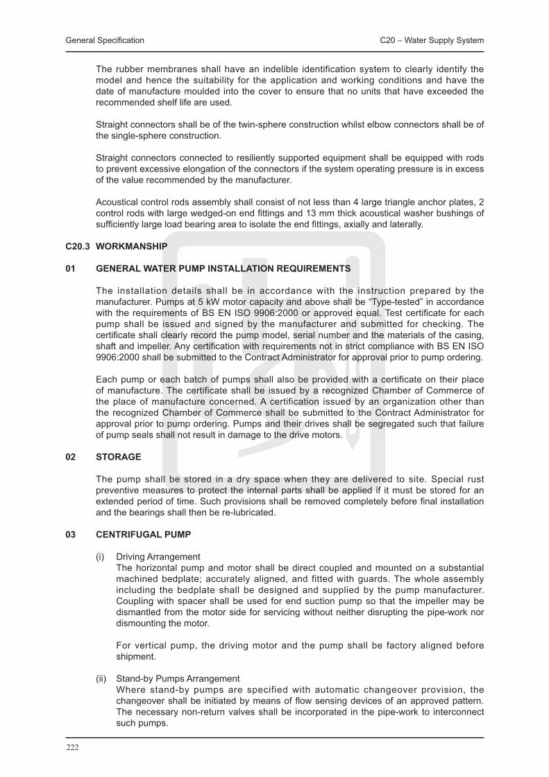
General Specification C20 – Water Supply System
222
The rubber membranes shall have an indelible identification system to clearly identify the model and hence the suitability for the application and working conditions and have the date of manufacture moulded into the cover to ensure that no units that have exceeded the recommended shelf life are used.
Straight connectors shall be of the twin-sphere construction whilst elbow connectors shall be of the single-sphere construction.
Straight connectors connected to resiliently supported equipment shall be equipped with rods to prevent excessive elongation of the connectors if the system operating pressure is in excess of the value recommended by the manufacturer.
Acoustical control rods assembly shall consist of not less than 4 large triangle anchor plates, 2 control rods with large wedged-on end fittings and 13 mm thick acoustical washer bushings of sufficiently large load bearing area to isolate the end fittings, axially and laterally.
C20.3 WORKMANSHIP
01 GENERAL WATER PUMP INSTALLATION REqUIREMENTS
The installation details shall be in accordance with the instruction prepared by the manufacturer. Pumps at 5 kW motor capacity and above shall be “Type-tested” in accordance with the requirements of BS EN ISO 9906:2000 or approved equal. Test certificate for each pump shall be issued and signed by the manufacturer and submitted for checking. The certificate shall clearly record the pump model, serial number and the materials of the casing, shaft and impeller. Any certification with requirements not in strict compliance with BS EN ISO 9906:2000 shall be submitted to the Contract Administrator for approval prior to pump ordering.
Each pump or each batch of pumps shall also be provided with a certificate on their place of manufacture. The certificate shall be issued by a recognized Chamber of Commerce of the place of manufacture concerned. A certification issued by an organization other than the recognized Chamber of Commerce shall be submitted to the Contract Administrator for approval prior to pump ordering. Pumps and their drives shall be segregated such that failure of pump seals shall not result in damage to the drive motors.
02 STORAGE
The pump shall be stored in a dry space when they are delivered to site. Special rust preventive measures to protect the internal parts shall be applied if it must be stored for an extended period of time. Such provisions shall be removed completely before final installation and the bearings shall then be re-lubricated.
03 CENTRIFUGAL PUMP
(i) Driving Arrangement The horizontal pump and motor shall be direct coupled and mounted on a substantial
machined bedplate; accurately aligned, and fitted with guards. The whole assembly including the bedplate shall be designed and supplied by the pump manufacturer. Coupling with spacer shall be used for end suction pump so that the impeller may be dismantled from the motor side for servicing without neither disrupting the pipe-work nor dismounting the motor.
For vertical pump, the driving motor and the pump shall be factory aligned before shipment.
(ii) Stand-by Pumps Arrangement Where stand-by pumps are specified with automatic changeover provision, the
changeover shall be initiated by means of flow sensing devices of an approved pattern. The necessary non-return valves shall be incorporated in the pipe-work to interconnect such pumps.

General Specification C20 – Water Supply System
223
04 PUMP ROOM LAYOUT
The Contractor shall check and assure that adequate working space shall be provided to access for maintenance and sufficient headroom to lift the parts for repair is provided. For large pump, a hoist with travelling crane or other facility shall be provided over the pump location.
For an open loop system, the location of pump shall be sited so that it will use the shortest and most direct suction and smallest vertical lift.
Where possible, the pump centreline shall be placed below the level of the liquid in the suction tank.
05 PUMP FOUNDATION
(i) The foundation shall be of sufficient size and rigidity to properly support the full area of the pump base-plate, to absorb any normal strains and to maintain correct alignment for the pump assembly.
(ii) Space between the pump unit and the foundation bolts shall be allowed in accordance with the manufacturer’s recommendation.
(iii) For vertical pump, the foundation shall be of sufficient size and rigidity to properly support
the full base area of the pump.
(iv) The foundation shall be surrounded by 50 mm thick cork and housed in a 100 mm thick concrete plinth. The cork shall enclose the 4 sides and the bottom of the foundation to isolate vibration generated by the pump to the floor structure. The cork and the concrete plinth and foundation shall be filled up with bitumen.
(v) For horizontal pump, an inertia block shall be provided, with minimum mass of concrete not less than 2.5 times the mass of the pump assembly and with at least 100 mm thick and 150 mm wider than the pump base-plate. Unless otherwise specified, the pump base shall be mounted on the raised housekeeping plinth using appropriate anti-vibration spring mountings. Each spring shall be individually selected according to load distribution and shall have an additional free travel equal to one half of the rated deflection. Spring mounts shall have a levelling bolt and shall be mounted to the concrete inertia block via height saving brackets that allows a base clearance of 50 mm. When the horizontal pump motor size is less than 5.5 kW and the pump is located in a pump room which is not susceptible to structural bond noise, the use of inertia block may not be necessary subject to Contract Administrator’s approval.
06 PUMP ALIGNMENT
The pump unit shall be accurately aligned in accordance with the manufacturer’s instructions prior to operation. The alignment shall be rechecked after the suction and discharge piping have been bolted to the pump to test the effect of piping strains. The pump and driver alignment shall be rechecked and adjusted correctly within ±0.05 mm tolerance.
07 SUPPORT FOR PIPING
Suction and delivery pipes shall be supported independently of the pump. The connecting pipes to a pump shall not strain the pump. Pipes installation shall match up to the respective flanges without being strained into position. The faces of the coupling shall be checked with a straight edge to make sure that they are parallel and concentric.
08 CONNECTION PIPING TO PUMP
(i) Suction Piping The suction piping shall be properly installed for a satisfactory pump operation. This shall
be achieved by keeping as direct and as short as practicably possible with a minimum

General Specification C20 – Water Supply System
224
number of bends, and by avoiding air pockets forming. Concentric reducers shall not be used on suction branch.
The size of the suction pipe shall be larger than the pump inlet and when applicable eccentric reducer may be used. If the source of supply is located below the pump centre line, the reducer shall be installed straight side up. If the source of supply is above the pump, the straight side of the reducer shall be at the bottom.
A straight section piping at least 4 to 6 diameters long at the pump inlet with long radius bend shall be used for suction pipeline installation to create less friction and provide more uniform flow distribution as deemed necessary.
(ii) Delivery Piping Unless otherwise specified, the size of the delivery pipe shall be at least one size larger
than the pump delivery. The check valve shall be installed between the pump and the gate valve.
The gate valve shall be installed close to the pump discharge for pump priming and repairing.
Air release valves shall be installed at the highest points on each rise to allow accumulated air or vapour or other gases to escape from the pipe.
Adequate support and anchorage shall be provided if the pipes are laid above or below ground. For this purpose, it is acceptable to have thrust blocks in either corner type or puddle flange type that are designed to absorb reactions or turning forces to ensure no mechanical and hydraulic forces are imposed on the pump.
(iii) Pipe Flanges Pipe flanges shall match with the sizes of pump flanges with full-face gaskets.
(iv) Expansion joints Expansion joints shall be installed in suction and delivery pipelines to avoid transmitting
any piping strains. A suitable pipe anchor shall be installed between the expansion joint and the pump. If expansion joints are not specified, expansion loops that are formed by looping the pipe shall be provided to prevent the transmission of strains to the pump.
09 FLUSHING STRAINER
The suction strainer shall be installed as close as practicably possible to the pump. This suction pipe strainer should not be used for flushing the pipe. A temporary strainer fitted with a finer mesh than the permanent strainer shall be used for flushing all piping and cleaning thoroughly all possible mill scale and other foreign matter. The temporary strainer shall be removed afterwards.
10 VENTING VALVES FOR PUMP-SET
Venting valves shall be installed at one or more points of the pump-casing waterway to provide a means to escape for air or vapour trapped in the casing. These valves shall be connected so as not to endanger the operation staff.
11 DRAINS FOR PUMP-SET
All drain and drip connections shall be piped to a point where the leakage can be disposed of or collected for reuse if specified.
12 INSTRUMENTATION
Each pump installation shall include pressure gauges and a gauge cock to measure the system pressures and pressure drop. All measuring and isolation instruments, such as
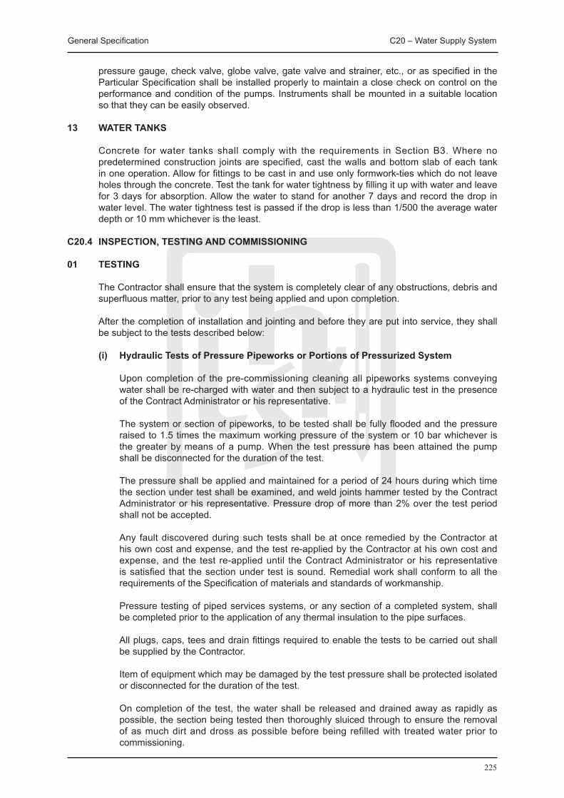
General Specification C20 – Water Supply System
225
pressure gauge, check valve, globe valve, gate valve and strainer, etc., or as specified in the Particular Specification shall be installed properly to maintain a close check on control on the performance and condition of the pumps. Instruments shall be mounted in a suitable location so that they can be easily observed.
13 WATER TANKS
Concrete for water tanks shall comply with the requirements in Section B3. Where no predetermined construction joints are specified, cast the walls and bottom slab of each tank in one operation. Allow for fittings to be cast in and use only formwork-ties which do not leave holes through the concrete. Test the tank for water tightness by filling it up with water and leave for 3 days for absorption. Allow the water to stand for another 7 days and record the drop in water level. The water tightness test is passed if the drop is less than 1/500 the average water depth or 10 mm whichever is the least.
C20.4 INSPECTION, TESTING AND COMMISSIONING
01 TESTING
The Contractor shall ensure that the system is completely clear of any obstructions, debris and superfluous matter, prior to any test being applied and upon completion.
After the completion of installation and jointing and before they are put into service, they shall be subject to the tests described below:
(i) Hydraulic Tests of Pressure Pipeworks or Portions of Pressurized System
Upon completion of the pre-commissioning cleaning all pipeworks systems conveying water shall be re-charged with water and then subject to a hydraulic test in the presence of the Contract Administrator or his representative.
The system or section of pipeworks, to be tested shall be fully flooded and the pressure raised to 1.5 times the maximum working pressure of the system or 10 bar whichever is the greater by means of a pump. When the test pressure has been attained the pump shall be disconnected for the duration of the test.
The pressure shall be applied and maintained for a period of 24 hours during which time the section under test shall be examined, and weld joints hammer tested by the Contract Administrator or his representative. Pressure drop of more than 2% over the test period shall not be accepted.
Any fault discovered during such tests shall be at once remedied by the Contractor at his own cost and expense, and the test re-applied by the Contractor at his own cost and expense, and the test re-applied until the Contract Administrator or his representative is satisfied that the section under test is sound. Remedial work shall conform to all the requirements of the Specification of materials and standards of workmanship.
Pressure testing of piped services systems, or any section of a completed system, shall be completed prior to the application of any thermal insulation to the pipe surfaces.
All plugs, caps, tees and drain fittings required to enable the tests to be carried out shall be supplied by the Contractor.
Item of equipment which may be damaged by the test pressure shall be protected isolated or disconnected for the duration of the test.
On completion of the test, the water shall be released and drained away as rapidly as possible, the section being tested then thoroughly sluiced through to ensure the removal of as much dirt and dross as possible before being refilled with treated water prior to commissioning.

General Specification C20 – Water Supply System
226
The Contractor shall carry out hydraulic tests as requested by the FSD and the Water Authority and shall ensure that all the hydraulic tests are satisfied with the FSD and the Water Authority regulations and requirements.
Pressurized pipework may be carried out in portions upon approval of the Contract Administrator.
(ii) Testing of Water Tanks
All water storage tanks or water containing structure, shall be filled with water and left to stand full for at least 24 hours, after which they shall not show any leak or permanent distortion. The initial filling shall be carried out within 7 days of completion or erection, and all costs of filling and emptying shall be included in the Contract.
02 COMMISSIONING
Systems (including condensate collection system) shall be twice flushed through from the high points prior to the completed systems being put into commission. All dirt pockets, drain pockets and strainers shall be cleaned on each occasion.
Particular care shall be taken to ensure that all parts liable to damage such as pumps, control valves, etc. are adequately protected.
The commissioning and balancing of the systems shall be carried out in accordance with the CIBS Commissioning Code Series W - Water Systems. Particular attention shall be paid to the permitted tolerances specified in these documents.
In addition to the above codes, systems shall generally be commissioned as follows:
(i) After the entire installation has been completed the equipment shall be operated under normal conditions prevailing at the time while making all required adjustments to balancing valves, air vents, automatic controls, plant items, etc. until all performance requirements are met. Properly balance all water circulating systems.
(ii) After all water systems have been balanced, a record shall be made of all regulating valve settings. All strainers shall be cleared and all valves shall be checked to ensure they are operational.
Pumps shall be fitted with pressure gauges on the suction and discharge connections. In addition the electrical consumption of the pump motor shall be recorded using a hand held portable instrument, or an ammeter installed as part of the installation. A copy of the test curve indicating the final operating points shall be included in the commissioning record forwarded to the Contract Administrator.

227
C21 FireServicesInstallationSystem

General Specification C21 – Fire Services Installation System
228
C21 FIRE SERVICES INSTALLATION SYSTEM
C21.1 GENERAL
All materials, and equipment to be incorporated in the Fire Services Installation at the Contractor’s works, shall comply with the requirements of this Section. These requirements shall be minimum requirements for general purposes and they shall not relieve the Contractor from ensuring that his designs are sound, and that all materials and equipment incorporated in the works are suitable for their intended purposes and environment.
Unless otherwise specified, the installation shall comply with the following documents:
(i) Electricity Ordinance, Chapter 406, and other subsidiary legislation made under the Ordinance;
(ii) Fire Service (Installation and Equipment) Regulations, Fire Services Ordinance, Chapter 95, and other subsidiary legislation made under the Ordinance;
(iii) Fire Safety (Buildings) Ordinance, Chapter 572, and other subsidiary legislation made under the Ordinance;
(iv) Waterworks Ordinance, Chapter 102, and other subsidiary legislation made under the Ordinance;
(v) Code of Practice for the Electricity (Wiring) Regulations published by the Electrical and Mechanical Services Department, the Government of the HKSAR;
(vi) Codes of Practice for Minimum Fire Service Installations and Equipment and Inspection, Testing and Maintenance of Installations and Equipment published by Fire Services Department, the Government of the HKSAR (hereinafter referred as FSDCoP);
(vii) Code of Practice for the Provision of Means of Escape In Case of Fire, Code of Practice for Fire Resisting Construction, and Code of Practice for Means of Access for Firefighting and Rescue published by the Buildings Department, the Government of the HKSAR;
(viii) All requirements of the FSD including FSD Circular Letters and Fire Protection Notices of the Fire Services Department, the HKSAR (hereinafter referred collectively as FSD Requirements and Circular Letters);
(ix) Loss Prevention Council Rules for Automatic Sprinkler Installations (including all the LPC Technical Bulletins, Notes, Commentary, and Recommendation) incorporating BS EN 12845:2004, FSD Circular Letter No. 3/2006, and all the subsequent amendments by the FSD (hereinafter referred collectively as LPC Rules for Sprinkler Installations).
No substitutions to these standards will be permitted without the endorsement of the Contract Administrator.
C21.2 MATERIALS AND EqUIPMENT
C21.2.1 EMERGENCY LIGHTING, EXIT SIGN AND EMERGENCY GENERATOR
01 GENERAL
Emergency lighting for fire escape purpose shall comply with BS 5266-1:2005, BS EN 50172:2004, BS 5266-8:2004, BS EN 1838:1999 and the requirements of the FSD and Building Authority.
Emergency lighting shall be backed up by emergency power supply.
In the event of power failure, the emergency lighting shall be activated within 5 seconds or within such shorter time specified elsewhere in the Specification upon mains power failure. To meet this requirement, emergency lighting shall be provided with secondary battery supply, uninterrupted power supply, or an approved source of backup power supply accepted by the Contract Administrator even when they are connected to the emergency generator.
Where an emergency generator is provided in a building for fire service installation, all emergency lighting systems with or without battery system shall be connected to and backed up by the emergency generator for fire fighting purpose.
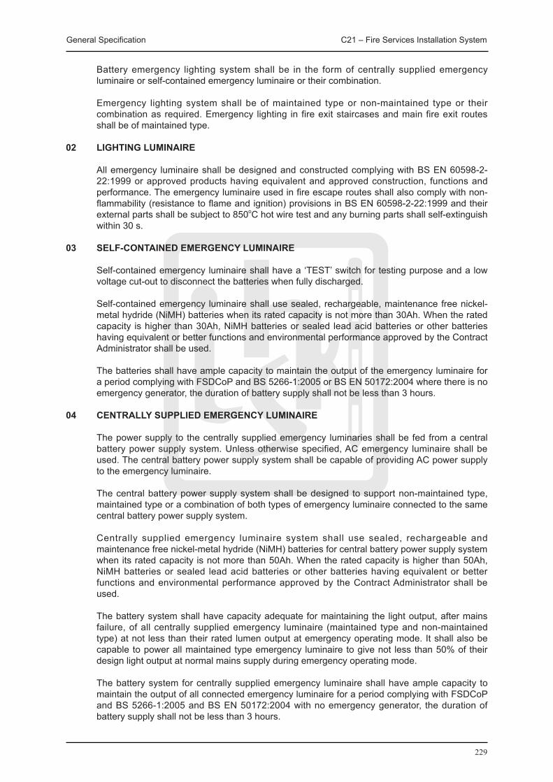
General Specification C21 – Fire Services Installation System
229
Battery emergency lighting system shall be in the form of centrally supplied emergency luminaire or self-contained emergency luminaire or their combination.
Emergency lighting system shall be of maintained type or non-maintained type or their combination as required. Emergency lighting in fire exit staircases and main fire exit routes shall be of maintained type.
02 LIGHTING LUMINAIRE
All emergency luminaire shall be designed and constructed complying with BS EN 60598-2-22:1999 or approved products having equivalent and approved construction, functions and performance. The emergency luminaire used in fire escape routes shall also comply with non-flammability (resistance to flame and ignition) provisions in BS EN 60598-2-22:1999 and their external parts shall be subject to 850oC hot wire test and any burning parts shall self-extinguish within 30 s.
03 SELF-CONTAINED EMERGENCY LUMINAIRE
Self-contained emergency luminaire shall have a ‘TEST’ switch for testing purpose and a low voltage cut-out to disconnect the batteries when fully discharged.
Self-contained emergency luminaire shall use sealed, rechargeable, maintenance free nickel-metal hydride (NiMH) batteries when its rated capacity is not more than 30Ah. When the rated capacity is higher than 30Ah, NiMH batteries or sealed lead acid batteries or other batteries having equivalent or better functions and environmental performance approved by the Contract Administrator shall be used.
The batteries shall have ample capacity to maintain the output of the emergency luminaire for a period complying with FSDCoP and BS 5266-1:2005 or BS EN 50172:2004 where there is no emergency generator, the duration of battery supply shall not be less than 3 hours.
04 CENTRALLY SUPPLIED EMERGENCY LUMINAIRE
The power supply to the centrally supplied emergency luminaries shall be fed from a central battery power supply system. Unless otherwise specified, AC emergency luminaire shall be used. The central battery power supply system shall be capable of providing AC power supply to the emergency luminaire.
The central battery power supply system shall be designed to support non-maintained type, maintained type or a combination of both types of emergency luminaire connected to the same central battery power supply system.
Centrally supplied emergency luminaire system shall use sealed, rechargeable and maintenance free nickel-metal hydride (NiMH) batteries for central battery power supply system when its rated capacity is not more than 50Ah. When the rated capacity is higher than 50Ah, NiMH batteries or sealed lead acid batteries or other batteries having equivalent or better functions and environmental performance approved by the Contract Administrator shall be used.
The battery system shall have capacity adequate for maintaining the light output, after mains failure, of all centrally supplied emergency luminaire (maintained type and non-maintained type) at not less than their rated lumen output at emergency operating mode. It shall also be capable to power all maintained type emergency luminaire to give not less than 50% of their design light output at normal mains supply during emergency operating mode.
The battery system for centrally supplied emergency luminaire shall have ample capacity to maintain the output of all connected emergency luminaire for a period complying with FSDCoP and BS 5266-1:2005 and BS EN 50172:2004 with no emergency generator, the duration of battery supply shall not be less than 3 hours.
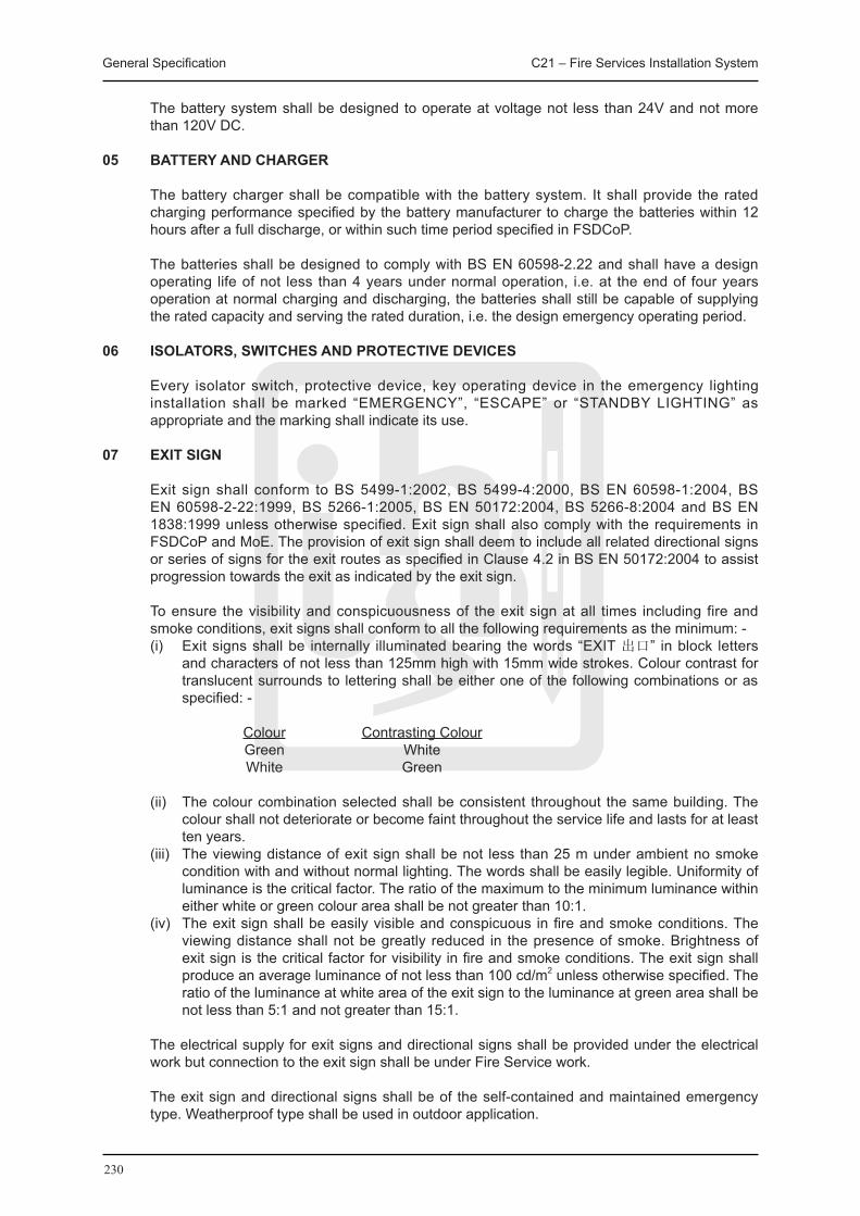
General Specification C21 – Fire Services Installation System
230
The battery system shall be designed to operate at voltage not less than 24V and not more than 120V DC.
05 BATTERY AND CHARGER
The battery charger shall be compatible with the battery system. It shall provide the rated charging performance specified by the battery manufacturer to charge the batteries within 12 hours after a full discharge, or within such time period specified in FSDCoP.
The batteries shall be designed to comply with BS EN 60598-2.22 and shall have a design operating life of not less than 4 years under normal operation, i.e. at the end of four years operation at normal charging and discharging, the batteries shall still be capable of supplying the rated capacity and serving the rated duration, i.e. the design emergency operating period.
06 ISOLATORS, SWITCHES AND PROTECTIVE DEVICES
Every isolator switch, protective device, key operating device in the emergency lighting installation shall be marked “EMERGENCY”, “ESCAPE” or “STANDBY LIGHTING” as appropriate and the marking shall indicate its use.
07 EXIT SIGN
Exit sign shall conform to BS 5499-1:2002, BS 5499-4:2000, BS EN 60598-1:2004, BS EN 60598-2-22:1999, BS 5266-1:2005, BS EN 50172:2004, BS 5266-8:2004 and BS EN 1838:1999 unless otherwise specified. Exit sign shall also comply with the requirements in FSDCoP and MoE. The provision of exit sign shall deem to include all related directional signs or series of signs for the exit routes as specified in Clause 4.2 in BS EN 50172:2004 to assist progression towards the exit as indicated by the exit sign.
To ensure the visibility and conspicuousness of the exit sign at all times including fire and smoke conditions, exit signs shall conform to all the following requirements as the minimum: -
(i) Exit signs shall be internally illuminated bearing the words “EXIT 出口” in block letters and characters of not less than 125mm high with 15mm wide strokes. Colour contrast for translucent surrounds to lettering shall be either one of the following combinations or as specified: -
Colour Contrasting Colour Green White White Green
(ii) The colour combination selected shall be consistent throughout the same building. The colour shall not deteriorate or become faint throughout the service life and lasts for at least ten years.
(iii) The viewing distance of exit sign shall be not less than 25 m under ambient no smoke condition with and without normal lighting. The words shall be easily legible. Uniformity of luminance is the critical factor. The ratio of the maximum to the minimum luminance within either white or green colour area shall be not greater than 10:1.
(iv) The exit sign shall be easily visible and conspicuous in fire and smoke conditions. The viewing distance shall not be greatly reduced in the presence of smoke. Brightness of exit sign is the critical factor for visibility in fire and smoke conditions. The exit sign shall produce an average luminance of not less than 100 cd/m2 unless otherwise specified. The ratio of the luminance at white area of the exit sign to the luminance at green area shall be not less than 5:1 and not greater than 15:1.
The electrical supply for exit signs and directional signs shall be provided under the electrical work but connection to the exit sign shall be under Fire Service work.
The exit sign and directional signs shall be of the self-contained and maintained emergency type. Weatherproof type shall be used in outdoor application.
General Specification C21 – Fire Services Installation System
231
C21.2.2 HYDRANT AND HOSE REEL SYSTEM
01 GENERAL
The hydrant and hose reel system and the individual equipment installations shall comply with FSDCoP, FSD Requirements and Circular Letters.
The fire service inlets, hydrant outlet valves and hose reels shall be FSD approved type. This equipment shall be stamped with relevant British Standard Mark or accompanied with a valid letter of approval issued by the Water Supplies.
02 FS INLET
F.S. inlet shall be constructed of gunmetal or brass body, bronze extruded spindle, aluminium or cast iron hand wheel approved by FSD.
Twin inlet shall be parallel of inclined at 65° with each other and constructed of 65mm instantaneous male couplings.
The inlet shall be clearly marked in English and Chinese.
An integral spring loaded resilient seated non-return valve shall be fitted behind each inlet.
A drain cock shall be provided to each inlet.
Each inlet shall be affixed with a stainless steel identification plate engraved with the words ‘FIRE SERVICE INLET’ in English and ‘消防入水掣’ in Chinese characters of at least 50mm high.
03 FIRE HYDRANT OUTLET
Hydrant outlet shall be constructed of gunmetal body to BS 5041:1987, bronze extruded spindles and aluminium or cast iron hand-wheel approved by FSD.
The outlet shall be 63.5mm standard female instantaneous type to BS 336:1989.
The hydrant outlet shall be capable to withstand a working pressure of not less than 16 bars.
The direction of opening of the valve shall be clearly engraved in both Chinese and English on the wheel.
04 VENTING AND DRAINING
All hydrant risers shall be supplied and installed with automatic air vents of 25 mm size at the highest points and drain valves at the lowest points of the systems.
05 PRESSURE REDUCING HYDRANT OUTLETS
Pressure reducing hydrant outlet shall be supplied and installed at outlet locations where the static and pump pressure exceeds 700 kPa.
The pressure reducing hydrant outlet shall be in the form of a parity valve incorporated in the hydrant outlet and valve assembly with suitable connection to the drain pipe not less than 40 mm diameter. Alternatively, where specified, the pressure reducing hydrant outlet can be in the form of self-contained type without the use of the parity valve and drain pipe. It shall be capable to reduce the running pressure and satisfy the flow test requirements. The pressure reducing mechanism of the valve shall be located at down stream of the valve seat. Pressure reduction shall be achieved by means of hydraulic pressure balancing with metal diaphragm. The 100% effectiveness pressure reducing performance shall be maintained at all times of operation.

General Specification C21 – Fire Services Installation System
232
06 HOSE REEL
Reel drum and reel disc shall be constructed in mild steel and the reel stem shall be in brass to the requirement of FSD.
The hose reel shall be completed with 30 meter 19 mm diameter non-kinking, rubber hose fitted with a two way plastic shut off valve to FSD approved pattern. The rubber hose and nozzle shall be of FSD approved type.
For the wall fixed type, wall-mounting brackets of substantial construction shall be capable in supporting the entire weight of the hose reel and tubing under all operating conditions as required.
For the swing-out type, the support brackets and the swing-out arm shall enable the whole hose reel assembly to be swung through 180o in a horizontal plan.
Each hose reel nozzle shall be housed inside a glass fronted metal box. The box shall be fabricated from sheet metal not less than 0.8 mm thick with a hinged door with front break glass and padlocking facility. The metal box shall be painted and finished to the satisfaction of the Contract Administrator. The break glass shall be of fragile type not more than 1.5 mm thick. The break glass shall be easily replaced. Common key shall be used for the padlocks. Five common keys shall be provided. A metal or plastic striker about 300 mm long, secured by steel chains, shall be provided for each box for the purpose of breaking the glass panel in case of emergency.
C21.2.3 PORTABLE HAND-OPERATED APPROVED APPLIANCES
01 GENERAL
Portable hand-operated approved appliances shall comply with FSDCoP and where applicable BS 5306-3:2006.
02 SAND BUCKETS
Sand buckets shall conform to the requirements of the FSD. Sand bucket shall be galvanized steel painted in red and 0.01 cubic metre in capacity and fill with dry sand. Wooden/ Steel stand shall be provided for the sand bucket.
03 FIRE BLANKETS
Fire blankets shall comply with BS 7944:1999.
Fire blankets shall be heavy duty and reusable type and approved by the FSD and made of cloth woven with fibreglass and the size shall not be less than 1200 x 1200mm.
04 FIRE EXTINGUISHERS
Fire extinguishers shall be rechargeable hand-operated extinguishers complying with FSDCoP and of appropriate type to BS EN 3-7:2004+A1:2007, NFPA 10:2007, ISO 7165:2009, BS 5306-3:2009 and BS 7863:2009 for water, foam, dry powder, carbon dioxide, NASF III, FM200 or other approved agent type with a capacity as specified.
Fire extinguishers shall be manufactured and tested to recognized international standards.
Portable fire extinguisher shall be constructed with aluminium alloy, anodized for corrosion protections and equipped with solid brass operating head fitted with a brass discharge nozzle and piercing spindle connected by a stainless steel spring to a chrome-plated brass operating handle.
Fire extinguisher shall be operable to -40°C.

General Specification C21 – Fire Services Installation System
233
A sturdy wall hanger shall be provided for proper fixing of fire extinguisher.
The necessary operation, maintenance and re-loading instructions (including capacity, due date of annual inspection, types of fire suitable, gross and net weight) shall be clearly displayed permanently on the extinguisher body.
C21.2.4 MANUAL AND AUTOMATIC FIRE ALARM SYSTEM
01 BREAK GLASS UNIT
Break glass unit shall comply with BS EN 54-11:2001 and shall be LPC/UL listed and be approved by FSD.
Break glass unit shall have at least 2 pairs of normal-open (NO) contacts, and one pair of normal-close (NC) contact.
The NO contacts shall close and NC contacts shall open immediately when the front glass is smashed.
The unit shall be of pleasing appearance and styling, constructed of non-corrodible materials and finished enamel red. The words “In case of fire, Break Glass” shall be engraved or embossed on the front in both English and Chinese characters.
The unit shall be suitable for 24V D.C. operation. The contacts shall be of silver or approved non-deteriorating alloy.
The breaking of the glass shall not release an alarm. The glass plate shall be designed in a way to prevent injuries when struck by the personnel. The pushing of the call button will initiate an alarm.
The unit shall be possible to test without breaking the glass by use of a special tool.
Generally, the unit shall be fixed at a height of 1.15 m above finished floor level unless otherwise required to comply with the universal accessibility best practices. They shall be surface mounted, or semi-recessed, in order to present a side profile area of not less than 750 mm2.
The unit shall be provided at all escape routes and in particular at each hose reel point, all storey exits and all exits to open air.
Manual call points shall be of addressable type when analogue addressable manual and automatic fire alarm system is provided.
02 HEAT DETECTORS
All heat detectors shall comply with BS EN 54 Part 5:2001, and the FOC Rules, and shall be of the manufacturer and type approved by FSD and listed by the Fire Offices’ Committee.
All heat detectors shall be housed in corrosion-proof, plug-in unit designed to be mounted on a false ceiling or concrete soffit.
The detector shall be capable of operating satisfactorily under a reasonable variation in supply voltage such as may normally occur in service due to charging and discharging of the alarm system battery.
All detectors shall have alarm condition, neon lamp indicators, which can only be reset locally after actuation of the detector. Where detectors are installed inside a normally unoccupied area, the neon indicators shall be extended to a location outside the area.
Detectors shall have removable protective covers to enable thorough cleaning. Detectors shall
General Specification C21 – Fire Services Installation System
234
not be capable of further dismantling.
Heat detector shall function correctly at ambient temperature between -20oC to the maximum application temperature specified in BS EN 54-5:2001 for respective class. Heat detector shall be designed to assume minimum protection rating of IP 43.
Installation of heat detector shall be in accordance with the LPC Rules for AFA installations.
Heat detector shall be mounted not less than 500 mm away from any walls or partitions and not less than 25 mm or more than 150 mm below the ceiling or roof. In open areas under flat horizontal ceilings, the horizontal distance between any point in the area and the nearest point-type heat detector shall not exceed 5.3 m.
03 SMOKE DETECTOR
Smoke detector shall be of proprietary design to avoid false fire alarms. The Contractor shall supply and install smoke detectors that have good track record or job reference on no false fire alarm.
Smoke detector shall function correctly at continuous ambient temperature between 0oC and 48oC, relative humidity up to 99% continuous non-condensing in non-air-conditioned space and relatively humidity up to 95% continuous non-condensing in air-conditioned space unless otherwise specified.
Smoke detector shall be housed in a corrosion-proof plug-in unit designed to mount pendent, surface or semi-recessed as specified. Sensitivity shall be adjustable by means of a pre-set control only accessible by use of a special tool or in the central fire alarm control system.
Smoke detector installed inside lift shaft and outdoors shall be completed with extra wind-shield to cater for higher air current and shall also be of harsh type with anti-condensation facilities designed for higher temperature fluctuation, relative humidity and dirt accumulation.
Smoke detector shall have normal working life (mean failure time) of not less than 10 years.
Installation of smoke detector shall be in accordance with the LPC Rules for AFA Installations.
04 ALARM BELL
Alarm bells shall be of minimum 150 mm diameter gong suitable for 24 V DC operations. They shall comply with BS EN 54-3:2001. Each alarm bell shall be capable of producing a minimum sound level of 80 dB(A) at 3 m.
The bell shall consist of a micro motor as the driving unit offering high performance and reliability together with low current consumption and low starting voltage characteristics.
The bells shall be painted red and labeled “FIRE ALARM 火警警鐘” in both English and Chinese.
The alarm bells shall produce an alarm sound level complying with BS 5839-1:2002 in all accessible parts of the buildings when the doors of the rooms are closed.
The alarm bells shall be sited and distributed throughout the buildings to produce the alarm sound level.
05 ALARM INDICATION LAMP FOR DETECTOR
Where detectors are installed inside plant rooms, electrical equipment rooms, store rooms, dangerous good stores etc. which are unoccupied and normally kept locked, similar remote indicator lamps shall be supplied and installed above the doors outside the rooms to show the alarm status. If there is more than one detector inside the room, the indicator lamps shall be connected to a common remote indicator lamp mounted above the door outside the room.
General Specification C21 – Fire Services Installation System
235
C21.2.5 INTELLIGENT ADDRESSABLE DEVICE
01 GENERAL
All devices in the addressable fire alarm system shall be of analogue addressable type, and of type approved by the Contract Administrator, including the detectors, manual call points, flow switches, pressure sensors etc. where appropriate.
Each device/detector shall be addressable via a mechanism approved by the Contract Administrator. The address of each unit shall be easily set and changed. The allowable address shall be adequate to cater for the whole fire alarm system with ample spare capacity for future expansion. Dip switch type address setting mechanism is generally not preferred. Unless otherwise approved by the Contract Administrator, the address setting mechanism shall be attached to the base of the device/detector so that the device/detector head can be changed and replaced without the need to re-set the address. The device/detector shall constantly verify against the database in the addressable fire alarm control and indicating panel via an addressable detection cable loop.
Addressable devices shall provide information for continuous monitoring and control of detector status and annunciate the need for immediate service. The decision on the control actions shall however be from the fire alarm control system and not on individual detector. Connection wires for the addressable devices shall be of approved type by the Contract Administrator. Unless otherwise specified, twisted pairs in concealed conduits for point-to-point connection shall be used.
Detector shall be fully compensated for temperature, humidity and barometric changes in the surroundings. All electronic components shall be hermetically sealed to prevent their operation from being impaired by dust, dirt, humidity, corrosion or mechanical shock. All circuitry must be protected against typical electrical transients and electromagnetic interference according to BS EN 608012/ BS EN 61000-4~11 BS EN 61000-4-3 / IEC 801-3. The termination shall be so designed that the terminals are polarity insensitive. Built-in testing facility shall be provided.
One LED indicator designed for 360 degree viewing or two built-in LED indicators shall be provided for each detector unless otherwise accepted by the Contract Administrator and they shall be so positioned that at least one LED can be seen from any angle.
Remote LED indicator may be added to substitute one of the built-in LED indication requirement when approved. The detector shall have provisions to drive remote visual alarm indicator. Remote indicator shall be compatible with the detector so that the operation of the indicator shall not affect the brightness of the detector’s built-in LED.
02 ADDRESSABLE HEAT DETECTOR
Addressable heat detector shall continuously measure the temperature of air and generate a proportional analogue output.
The detector shall employ two matched thermal sensing elements in a bridge configuration to give a response which depends both on temperature and the rate of change of temperature. The reference and sensing thermal sensors shall be fabricated under identical conditions to ensure good matching and excellent tracking with both temperature and ageing.
03 ADDRESSABLE SMOKE DETECTOR
Addressable smoke detector shall continuously measure the products of combustion in the air and generate a proportional analogue output.
The measuring chamber shall be so designed to create a very low background signal in clean air condition. A specially designed device shall be incorporated to control dust settlement on non-critical surfaces so that high dust level in the surroundings can be tolerated.
General Specification C21 – Fire Services Installation System
236
04 ADDRESSABLE MANUAL CALL POINT
The addressable manual call point shall be of a type approved by the Contract Administrator.
05 FEATURES
The addressable detectors (heat, smoke or others) shall be provided with the following features as a minimum: -
(i) Remote adjustment of detector sensitivity to suit the occupancy and/or the environment of a detector at any time;
(ii) Sensor monitoring with automatic compensation of sensor alarm threshold due to aging, humidity and accumulation of dirt and dust with time (automatic drift compensation);
(iii) Adjustable time lag from the time of reaching alarm threshold to the time of issuing or communicating a fire alarm (pre-alarm, alarm verification);
(iv) Different alarm levels are provided such as detection level, maintenance or regular servicing level, fire alarm level etc. to give an early warning for maintenance to avoid false fire alarm (multi-sensitivity levels, day/night adjustment, and maintenance alert);
(v) Alarm condition simulation for testing purpose; and
(vi) Loop monitoring for error such as short circuit, open circuit, detector removed and detector communication failure (auto detector test, circuitry test).
C21.2.6 ADDRESSABLE INTERFACE MODULE
01 GENERAL
Various modules shall be provided for the addressable automatic fire alarm system for the required functions, interfacing with non-addressable devices and other services. Modules shall be mounted into junction boxes for easy installation. The addresses of these modules shall be easily set, seen and changed.
The module shall have a conspicuously located LED, which blinks or does not blink, upon being scanned by the panel. Upon determination of an alarm condition, the LED shall be latched on and blink or not blink as assigned.
02 MONITOR MODULE
Monitor module allows the panel to interface with and monitor individual non-addressable monitoring alarms, such as a non-addressable manual call point, sensors, detectors, water flow switches, sprinkler supervisory devices etc.
The module shall provide addressable inputs for all N.D. or N.C. contact for continuous monitoring. In addition to the supervised state of the monitored device, the measurement of the supervision shall be sent to the addressable automatic fire alarm control and indicating panel.
The monitor module shall also provide a supervised initiating circuit. An open-circuit or short-circuit fault shall be indicated at the fire alarm control and indicating panel.
Facilities shall be provided for carrying testing at the monitor module during maintenance and diagnostics.
03 CONTROL MODULE
Control module supervises and monitors wiring to appliances of small connected load like alarm bells, flashing light units, indicator units, and interface relays. Upon command from the
General Specification C21 – Fire Services Installation System
237
addressable automatic fire alarm control and indicating panel, the module shall disconnect the supervision and connect the external power supply to the device and a signal shall then be sent to the panel to indicate that the command was executed. The external power shall be isolated, so a trouble condition at the power supply shall not interfere with the rest of the system.
The connected alarm load shall be closely monitored for any open and short circuit conditions. The output circuit connected to the loading shall be short circuit protected.
04 FAULT ISOLATOR MODULE
The non-addressable fault isolator module shall detect and isolate a short-circuited segment of a fault-tolerant loop whilst allowing the rest of the addressing circuit to function normally.
At least one fault isolator module shall be provided for every 20 intelligent addressable devices, i.e. detectors, monitor modules and control modules to limit the number of devices lost in the event of a short-circuit.
C21.2.7 SPECIAL DETECTION SYSTEM
Special detection systems, including optical light beam smoke detection system (complying with BS EN 54-12:2002), VESDA (very early smoke detection alarm system), line-type heat detection system, flame detection system (complying with BS EN 54-10:2002), aspirating smoke detection system (complying with BS EN 54-20), carbon monoxide detection system, gas detection system, infrared detection system, ultraviolet detection system, video smoke detection system, dust detection system etc. shall be provided where specified or where required to meet with the requirements for a particular application. The detection system shall be of a type acceptable to the FSD and approved by the Contract Administrator. Selection of special detection system shall be to suit a particular application, environmental condition and fire hazard. The Contractor shall submit detailed performance data, equipment catalogue, description, technical information, test report and certificate to the Contract Administrator for approval. The Contractor shall submit information proving the suitability of the special detection system for approval.
C21.2.8 AUTOMATIC SPRINKLER SYSTEM
01 GENERAL
Sprinkler heads shall be of LPC approved type and be approved by HKFSD. For general application, quartzoid bulb spray type 68oC sprinkler head shall be used.
All necessary equipment, components, materials, testing devices, testing facilities, controls, signs, notices, etc. as so required according to LPC Sprinkler Rules and appropriate FSD requirements shall be fully provided to complete entire sprinkler system.
02 SPRINKLER HEAD
Type and finish Sprinkler heads shall be approved by F.O.C./L.P.C. and suitable for either upright or pendent
position or side wall or concealed types as indicated on Drawings and with the following finish: (i) All exposed metal parts of the sprinkler heads shall be chromium plated. (ii) Sprinklers on suspended ceiling shall be of pendent glass bulb type and provided with
ceiling plate for base flush fitting to the false ceiling with the heat-sensitive element below the false ceiling line.
(iii) In concealed spaces and service areas, the sprinkler heads shall be of glass bulb plain brass spray pattern type.
Temperature Rating Generally, the temperature rating of sprinkler heads shall have a nominal temperature rating of
68 degree C.
General Specification C21 – Fire Services Installation System
238
Orifice Sizes The sprinkler head orifice sizes shall be 15mm.
03 SPRINKLER INLETS
Sprinkler inlets shall be of the F.S.D. approved type. Each inlet shall consist of twin 65mm instantaneous male coupling and complete with an integral non-return valve. A 25mm diameter drain valve shall be incorporated and connected to an appropriate drain outlet.
The inlet couplings shall be not less than 600mm nor more than 1000mm above the ground level.
04 SPRINKLER CONTROL VALVE SETS
Each control valve set shall be complete with the following: (i) Main stop valve and subsidiary stop valve (ii) Alarm valve water motor alarm gong (iii) Water motor alarm gong (iv) Pressure gauges to indicate ‘up-stream’ and ‘downstream’ system pressure (v) Test and drain valve (vi) Permanent direct reading flow meter.
Every stop valve in the sprinkler installation including the main stop valve shall be secured open by a leather strap and brass lock under the master key system.
C21.2.9 TANKS AND PUMPS
01 WATER TANKS
Water tanks shall be constructed in compliance with FSDCoP, LPC Rules for Sprinkler Installations, FSD Requirements and Circular Letters, and the requirements of Water Supplies Department.
Puddle flanges for inlet and outlet pipes shall be supplied by the Contractor and installed by the Contractor unless otherwise specified. All other piping connections and valves shall be supplied and installed by the Contractor except overflow, drains and inlet piping which will be supplied and installed by Building Contractor unless otherwise specified.
02 WATER PUMPS
Water pumps for sprinkler systems shall comply with the LPC Rules for Sprinkler Installations. Sprinkler pumps shall be approved by LPCB or other similar widely recognized independent regulatory body acceptable by the Contract Administrator.
Water pumps for hydrant/hose reel systems shall comply with FSDCoP, FSD Requirements and Circular Letters and wherever applicable BS 5306-1:1988. Pumps shall be manufactured by a manufacturer possessing certified ISO 9001:2000 quality assurance system.
There shall be at least one standby pump in addition to the duty pumps for each pump set. In addition, there shall be at least one jockey pump installed for each sprinkler pump set.
03 FACTORY TEST AND CERTIFICATION
All sprinkler pumps before delivery shall be factory tested and certified on the performance. Factory test certificates and records shall be submitted to the Contract Administrator. Where the manufacturer does not have an approved test facilities required by the LPCB for the test in the factory, the Contractor shall, before delivery, arrange the test to be carried out by an independent testing organization approved by the LPCB or a widely recognized approved independent regulatory body acceptable to the Contract Administrator. On-site test will not be accepted as a substitute for the factory test or the test by the independent testing organization.
General Specification C21 – Fire Services Installation System
239
Test certificates endorsed by the independent testing organization shall be submitted to the Contract Administrator for approval and record.
Package fire pump set shall be factory tested and certified with all test details same as the sprinkler pump.
Where specified, factory test and certification shall be provided for other pumps adopting the same requirements as the sprinkler pump.
C21.3 WORKMANSHIP
C21.3.1 ELECTRICAL WORK FOR FIRE SERVICES INSTALLATION
01 GENERAL
The Contractor shall employ Registered Electrical Workers of the appropriate grades in accordance with the Electricity Ordinance to carry out the electrical works for the fire service installation. All relevant certificates/test reports shall be duly signed by the Registered Electrical Contractor and the Registered Electrical Workers and submitted to the Contract Administrator for record.
02 EARTHING
Proper earthing shall be supplied and installed for the electrical and electronic equipment as well as bonding of all exposed conductive parts of the fire service installation to the main earthing system.
03 FIRE RESISTING CABLE
Fire resistant cables used for fire service installation shall be of low smoke zero halogen type and shall comply with all the following standards:
(i) BS 6387:1994 Category CWZ; (ii) BS EN 50200 (class PH30 or better); (iii) BS EN 61034-1:2005 or IEC 61034-1 or 2:2005; (iv) BS EN 50267-2:1999 or IEC 60754-1:1994 / IEC 60754-2:1991 (with less than 0.5% acid
gas emission and pH level for the gases evolved not less than 4.3); and (v) BS 7629-1:1997 or BS 7846:2000 where applicable for relevant types of cables under the
standard.
C21.3.2 PIPEWORKS
01 PIPEWORK INSTALLATION
Pitcher tees, bends, twin elbows etc. of pipework installation shall be of the same size as the pipes connected to them.
Tubes shall be reamed after cutting and shall be free from burrs, rust, scale, and other defects and shall be thoroughly cleaned and treated for corrosion protection before and after erection.
Joints shall not be made in the thickness of any wall, floor or ceiling.
Pipes pass through fire rated walls or floors shall be constructed of fireproof material by the Contractor.
Pipework shall follow the contours of walls. Generally, pipework shall avoid running near to or above electrical equipment, electrical appliances, cables, trunkings and conduits. The clearance between pipework and the wall and any other fixtures shall be not less than 25 mm.

General Specification C21 – Fire Services Installation System
240
02 PIPEWORK SUPPORTS
All pipework shall be properly supported with substantial hangers, anchors, brackets, saddles, guide etc. with adequate provision for expansion and contraction and for corrosion protection.
Pipework supports shall be arranged as close as practicably possible to joints and changes of direction and each support shall take its share of the load.
Vertical rising pipework shall be supported at the base, or as indicated, to withstand the total weight of the riser. Branches from risers shall not be used as a means of support for the riser.
C21.3.3 MISCELLANEOUS
01 LABELS & NOTICES
Labels and notices shall be supplied and installed for all pumps, valves, switches, gauges, indicators, cables, internal wiring terminals and all other equipment to facilitate operation and proper maintenance of the fire service installation.
Labels and notices required by statutory requirements shall be inscribed accordingly whereas other labels shall indicate name and purpose of the equipment together with ratings and commissioned set values where applicable.
Notices for safety warning and instructions shall be constructed of heavy gauge aluminium sheets painted with symbols or wording as appropriate.
Notices for instruction for operation and use of the equipment shall be provided as appropriate and necessary. Instructions for use shall be provided to all equipment for use by the general public and for operation by the operating staff.
Labels and notices shall be fixed by screws. Where drilling and tapping is impracticable, approved adhesive may be used subject to prior approval by the Contract Administrator. For pipelines or valves, where applicable, labels shall be fixed by means of a key ring attached to the upper corner of the pipe mounting bracket or the hand wheel of valves. The labels shall be suspended from brass or stainless steel chain loops over the relevant pipe.
Danger notices worded: “DANGER-PLANT ON AUTOMATIC START” in English and Chinese shall be supplied and installed adjacent to all automatically controlled motor-driven and engine-driven pumps.
02 SPARES AND TOOLS
The Contractor shall provide the types of spare parts generally for the particular plant and/or equipment that is subject to frictional wear, vibration or temperature fatigue, rupture to safety (or otherwise), corrosion, erosion, decay, limited operating life, unacceptable deposits and/or saturation, normal fair wear and tear and is likely to fail or reach an unacceptably low performance level.
The Contractor shall supply and install locked cabinet or cabinets in the plant room(s) and/or control room(s) for housing the spares and tools.
C21.3.4 MAINTENANCE SERVICES
01 GENERAL
The Contractor shall carry out full operational maintenance and emergency servicing of the Fire Services Installation as defined in this Section.
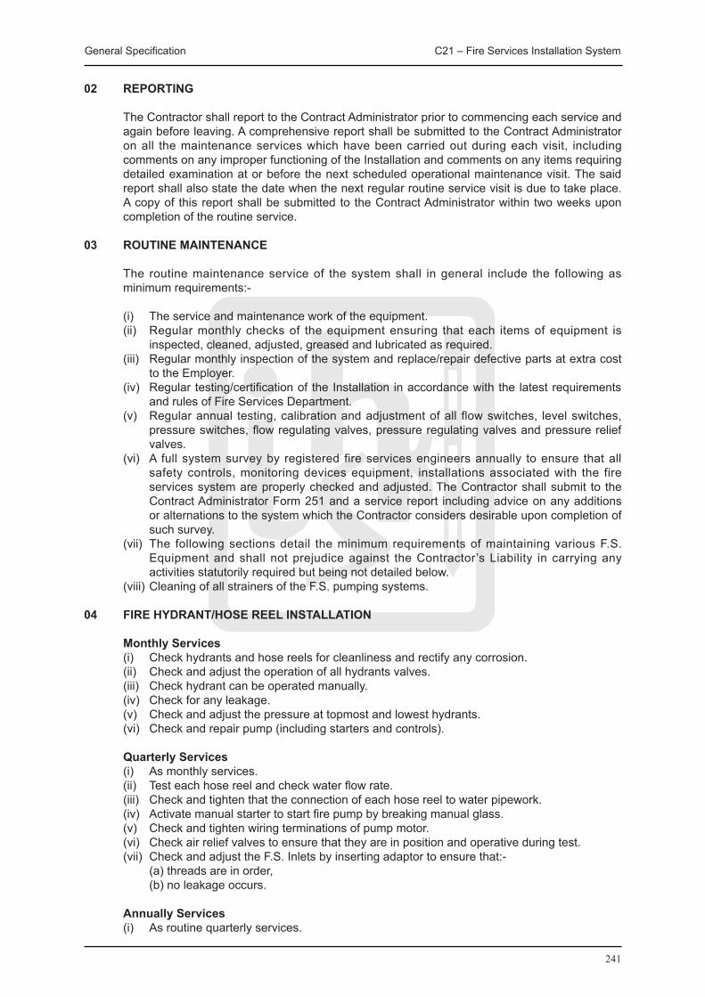
General Specification C21 – Fire Services Installation System
241
02 REPORTING
The Contractor shall report to the Contract Administrator prior to commencing each service and again before leaving. A comprehensive report shall be submitted to the Contract Administrator on all the maintenance services which have been carried out during each visit, including comments on any improper functioning of the Installation and comments on any items requiring detailed examination at or before the next scheduled operational maintenance visit. The said report shall also state the date when the next regular routine service visit is due to take place. A copy of this report shall be submitted to the Contract Administrator within two weeks upon completion of the routine service.
03 ROUTINE MAINTENANCE
The routine maintenance service of the system shall in general include the following as minimum requirements:-
(i) The service and maintenance work of the equipment. (ii) Regular monthly checks of the equipment ensuring that each items of equipment is
inspected, cleaned, adjusted, greased and lubricated as required. (iii) Regular monthly inspection of the system and replace/repair defective parts at extra cost
to the Employer. (iv) Regular testing/certification of the Installation in accordance with the latest requirements
and rules of Fire Services Department. (v) Regular annual testing, calibration and adjustment of all flow switches, level switches,
pressure switches, flow regulating valves, pressure regulating valves and pressure relief valves.
(vi) A full system survey by registered fire services engineers annually to ensure that all safety controls, monitoring devices equipment, installations associated with the fire services system are properly checked and adjusted. The Contractor shall submit to the Contract Administrator Form 251 and a service report including advice on any additions or alternations to the system which the Contractor considers desirable upon completion of such survey.
(vii) The following sections detail the minimum requirements of maintaining various F.S. Equipment and shall not prejudice against the Contractor’s Liability in carrying any activities statutorily required but being not detailed below.
(viii) Cleaning of all strainers of the F.S. pumping systems.
04 FIRE HYDRANT/HOSE REEL INSTALLATION
Monthly Services (i) Check hydrants and hose reels for cleanliness and rectify any corrosion. (ii) Check and adjust the operation of all hydrants valves. (iii) Check hydrant can be operated manually. (iv) Check for any leakage. (v) Check and adjust the pressure at topmost and lowest hydrants. (vi) Check and repair pump (including starters and controls).
quarterly Services (i) As monthly services. (ii) Test each hose reel and check water flow rate. (iii) Check and tighten that the connection of each hose reel to water pipework. (iv) Activate manual starter to start fire pump by breaking manual glass. (v) Check and tighten wiring terminations of pump motor. (vi) Check air relief valves to ensure that they are in position and operative during test. (vii) Check and adjust the F.S. Inlets by inserting adaptor to ensure that:- (a) threads are in order, (b) no leakage occurs.
Annually Services (i) As routine quarterly services.

General Specification C21 – Fire Services Installation System
242
(ii) Drain and clean all hydrant water tanks and check and report of any sign for leakage. (iii) Check, clean and adjust ball valves and level switches as required. (iv) Touch up paint work as necessary.
05 SPRINKLER SYSTEM
Monthly Services (i) Check and rectify any leakage and damage on all sprinklers and piping. (ii) Check and repair any leakage of sprinkler control valves and check system water
pressures. (iii) Check and repair water motor alarm. (iv) Check and repair sprinkler pumps (including starters and controls) by:- (a) Manual start, (b) Operation of flow switch, (c) Check all wiring terminations and secure, (d) Check F.S. Inlets by inserting adaptor, (e) Check water tank level.
quarterly Services (i) As monthly services. (ii) General cleaning and greasing on moving mechanism and valves.
Annually Services (i) As quarterly services. (ii) Drain and clean water tank. Report any sign of leakage. (iii) Clean and adjust ball valves of water tank/adjust flow switch and level switches. (iv) Touch up paint work as necessary. (v) Test run the sprinkler at on load condition with the power supply feed from emergency
generators to be operated by personnel of the Employer.
06 FIRE ALARM AND DETECTION SYSTEM
Monthly Services (i) Visual inspection for all manual break glass units, alarm bells and control panels are free
from mechanical damage and corrosion and that mains connected to these point functions are “ON”.
(ii) Check all fuses and D.C. batteries are in operating condition, including voltage, electrolyte specific gravity, etc.
(iii) Test line between panel and F.S.D. (iv) Spot check not less than 10 smoke detectors and/or heat detectors functions. (v) Spot check not less than 5 manual call points function. (vi) Check correct operation of the fire alarm and control panels and the fire control console
(including the printer). (vii) Check normal operation of fire services related computerized workstation system including
all interfacing panels.
quarterly Services (i) As monthly services. (ii) Check electrical main supply to control cabinet ensuring all line-supply and earth are
correctly connected at cabinet. (iii) Check main supply voltage. (iv) Check fire alarm panel for indication on:- (a) Fire under normal alarm condition, (b) Fault when mains are “OFF”, (c) Fault when batteries are disconnected, (d) Signal to Fire Control Centre. (v) Check to ensure indicating lamp of detector operates correctly.
Semi-Annually Services (i) As quarterly services.
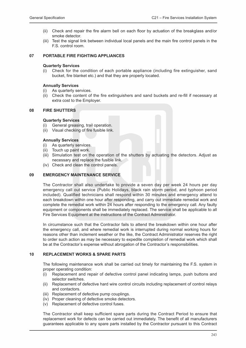
General Specification C21 – Fire Services Installation System
243
(ii) Check and repair the fire alarm bell on each floor by actuation of the breakglass and/or smoke detector.
(iii) Test the signal link between individual local panels and the main fire control panels in the F.S. control room.
07 PORTABLE FIRE FIGHTING APPLIANCES
quarterly Services (i) Check for the condition of each portable appliance (including fire extinguisher, sand
bucket, fire blanket etc.) and that they are properly located.
Annually Services (i) As quarterly services. (ii) Check the content of the fire extinguishers and sand buckets and re-fill if necessary at
extra cost to the Employer.
08 FIRE SHUTTERS
quarterly Services (i) General greasing, trail operation. (ii) Visual checking of fire fusible link.
Annually Services (i) As quarterly services. (ii) Touch up paint work. (iii) Simulation test on the operation of the shutters by actuating the detectors. Adjust as
necessary and replace the fusible link. (iv) Check and clean the control panels.
09 EMERGENCY MAINTENANCE SERVICE
The Contractor shall also undertake to provide a seven day per week 24 hours per day emergency call out service (Public Holidays, black rain storm period, and typhoon period included). Qualified technicians shall respond within 30 minutes and emergency attend to each breakdown within one hour after responding, and carry out immediate remedial work and complete the remedial work within 24 hours after responding to the emergency call. Any faulty equipment or components shall be immediately replaced. The service shall be applicable to all Fire Services Equipment at the instructions of the Contract Administrator.
In circumstance such that the Contractor fails to attend the breakdown within one hour after the emergency call, and where remedial work is interrupted during normal working hours for reasons other than inclement weather or the like, the Contract Administrator reserves the right to order such action as may be necessary to expedite completion of remedial work which shall be at the Contractor’s expense without abrogation of the Contractor’s responsibilities.
10 REPLACEMENT WORKS & SPARE PARTS
The following maintenance work shall be carried out timely for maintaining the F.S. system in proper operating condition:
(i) Replacement and repair of defective control panel indicating lamps, push buttons and selector switches.
(ii) Replacement of defective hard wire control circuits including replacement of control relays and contactors.
(iii) Replacement of defective pump couplings. (iv) Proper cleaning of defective smoke detectors. (v) Replacement of defective control fuses.
The Contractor shall keep sufficient spare parts during the Contract Period to ensure that replacement work for defects can be carried out immediately. The benefit of all manufacturers guarantees applicable to any spare parts installed by the Contractor pursuant to this Contract
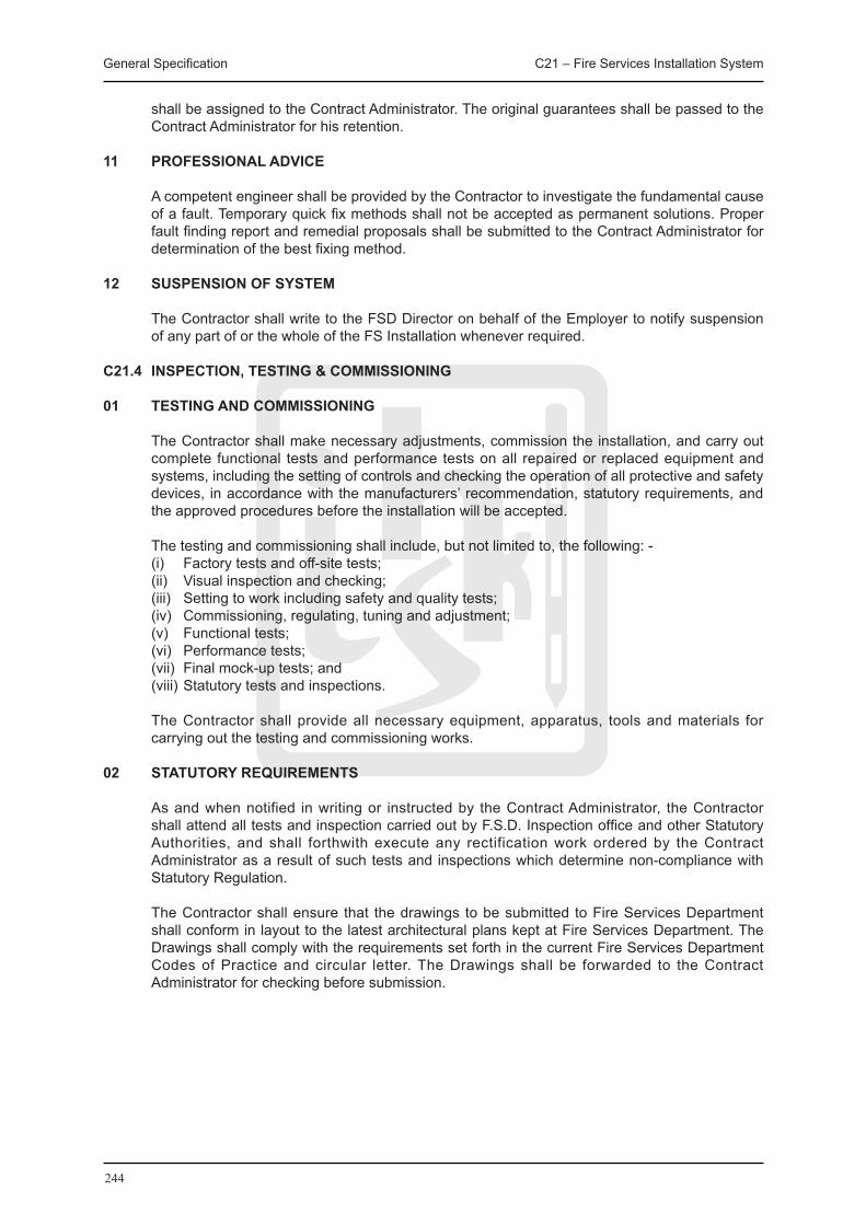
General Specification C21 – Fire Services Installation System
244
shall be assigned to the Contract Administrator. The original guarantees shall be passed to the Contract Administrator for his retention.
11 PROFESSIONAL ADVICE
A competent engineer shall be provided by the Contractor to investigate the fundamental cause of a fault. Temporary quick fix methods shall not be accepted as permanent solutions. Proper fault finding report and remedial proposals shall be submitted to the Contract Administrator for determination of the best fixing method.
12 SUSPENSION OF SYSTEM
The Contractor shall write to the FSD Director on behalf of the Employer to notify suspension of any part of or the whole of the FS Installation whenever required.
C21.4 INSPECTION, TESTING & COMMISSIONING
01 TESTING AND COMMISSIONING
The Contractor shall make necessary adjustments, commission the installation, and carry out complete functional tests and performance tests on all repaired or replaced equipment and systems, including the setting of controls and checking the operation of all protective and safety devices, in accordance with the manufacturers’ recommendation, statutory requirements, and the approved procedures before the installation will be accepted.
The testing and commissioning shall include, but not limited to, the following: - (i) Factory tests and off-site tests; (ii) Visual inspection and checking; (iii) Setting to work including safety and quality tests; (iv) Commissioning, regulating, tuning and adjustment; (v) Functional tests; (vi) Performance tests; (vii) Final mock-up tests; and (viii) Statutory tests and inspections.
The Contractor shall provide all necessary equipment, apparatus, tools and materials for carrying out the testing and commissioning works.
02 STATUTORY REqUIREMENTS
As and when notified in writing or instructed by the Contract Administrator, the Contractor shall attend all tests and inspection carried out by F.S.D. Inspection office and other Statutory Authorities, and shall forthwith execute any rectification work ordered by the Contract Administrator as a result of such tests and inspections which determine non-compliance with Statutory Regulation.
The Contractor shall ensure that the drawings to be submitted to Fire Services Department shall conform in layout to the latest architectural plans kept at Fire Services Department. The Drawings shall comply with the requirements set forth in the current Fire Services Department Codes of Practice and circular letter. The Drawings shall be forwarded to the Contract Administrator for checking before submission.

245
C22 Electrical Installation System

General Specification C22 – Electrical Installation System
246
C22 ELECTRICAL INSTALLATION SYSTEM
C22.1 GENERAL REqUIREMENTS
The contractor shall identify all necessary diversions of the existing building services and notify the Contract Administrator in writing with proposals, method statements and drawings. All services diversion associated with the Works shall be carried out by the contractor unless otherwise stated.
The contractor shall carry out a site survey and performance assessment of existing electrical
devices in Meter Room and LV Switch Room before work start. Moreover, the contractor shall notify the Contract Administrator in writing with report.
All cabling that not complied with the latest ordinance and regulations shall be replaced.
Newly installed trunking, cable tray and conduit with adaptable box shall be painted and labelled.
All temporary power fixtures and equipment and cables, costs used during the construction stage shall be born by the contractor.
Materials for electrical conduit systems and for cable duct systems shall be stored in accordance with the manufacturers’ recommendations in a dry and weatherproof store.
Holes and recesses shall be left in structures for electrical installations. If instructed by the Contract Administrator, holes and recesses shall be cut in structures for electrical installations.
Holes and recesses in internal floors, stairways and platforms shall be protected with temporary covers or by other methods agreed by the Contract Administrator until the electrical installation starts. Holes and recesses in roofs, external walls and external floors shall be sealed with watertight temporary covers until the electrical installation starts.
Holes in structures shall be filled and made good after electrical installations are complete. Holes left in structural elements designated as fire barriers shall be sealed to at least the same degree of fire resistance as the structural element.
The tolerance in floor levels for switchgear rooms shall be as follows: (i) ± 2 mm in 1000 mm for high voltage switchgear rooms, (ii) ± 4 mm in 1000 mm for medium voltage switchgear rooms.
The tolerance lamp standards shall be within 0.1 degrees of the vertical.
C22.2 MATERIALS AND EqUIPMENT SPECIFICATION
C22.2.1 ELECTRICAL CONDUITS AND FITTINGS
Electrical conduits and fittings shall comply with BS 4568:1970 Parts 1 and BS EN 50086-1:1994 and shall have Class 4 heavy protection inside and outside. Conduits shall be heavy gauge with screw-end construction in steel and shall have an external diameter of at least 20 mm. Conduits shall be longitudinally welded.
Metal boxes for enclosing electrical accessories shall comply with BS 4662:2006+A1:2009 and shall have heavy protection inside and outside. The boxes shall be of preferred sizes and shall be 35 mm or 47 mm deep as appropriate. Circular ceiling boxes of deep pattern shall comply with BS 4568:Part 2 and shall have Class 4 heavy protection inside and outside. The boxes shall be at least 60 mm deep internally.
Circular boxes, dome covers and hook covers shall be cast iron. Bushes and plugs shall be brass.
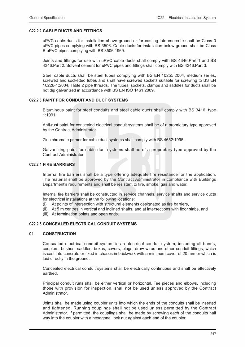
General Specification C22 – Electrical Installation System
247
C22.2.2 CABLE DUCTS AND FITTINGS
uPVC cable ducts for installation above ground or for casting into concrete shall be Class 0 uPVC pipes complying with BS 3506. Cable ducts for installation below ground shall be Class B uPVC pipes complying with BS 3506:1969.
Joints and fittings for use with uPVC cable ducts shall comply with BS 4346:Part 1 and BS 4346:Part 2. Solvent cement for uPVC pipes and fittings shall comply with BS 4346:Part 3.
Steel cable ducts shall be steel tubes complying with BS EN 10255:2004, medium series, screwed and socketted tubes and shall have screwed sockets suitable for screwing to BS EN 10226-1:2004, Table 2 pipe threads. The tubes, sockets, clamps and saddles for ducts shall be hot dip galvanized in accordance with BS EN ISO 1461:2009.
C22.2.3 PAINT FOR CONDUIT AND DUCT SYSTEMS
Bituminous paint for steel conduits and steel cable ducts shall comply with BS 3416, type 1:1991.
Anti-rust paint for concealed electrical conduit systems shall be of a proprietary type approved by the Contract Administrator.
Zinc chromate primer for cable duct systems shall comply with BS 4652:1995.
Galvanizing paint for cable duct systems shall be of a proprietary type approved by the Contract Administrator.
C22.2.4 FIRE BARRIERS
Internal fire barriers shall be a type offering adequate fire resistance for the application. The material shall be approved by the Contract Administrator in compliance with Buildings Department’s requirements and shall be resistant to fire, smoke, gas and water.
Internal fire barriers shall be constructed in service channels, service shafts and service ducts for electrical installations at the following locations:
(i) At points of intersection with structural elements designated as fire barriers, (ii) At 5 m centres in vertical and inclined shafts, and at intersections with floor slabs, and (iii) At termination points and open ends.
C22.2.5 CONCEALED ELECTRICAL CONDUIT SYSTEMS
01 CONSTRUCTION
Concealed electrical conduit system is an electrical conduit system, including all bends, couplers, bushes, saddles, boxes, covers, plugs, draw wires and other conduit fittings, which is cast into concrete or fixed in chases in brickwork with a minimum cover of 20 mm or which is laid directly in the ground.
Concealed electrical conduit systems shall be electrically continuous and shall be effectively earthed.
Principal conduit runs shall be either vertical or horizontal. Tee pieces and elbows, including those with provision for inspection, shall not be used unless approved by the Contract Administrator.
Joints shall be made using coupler units into which the ends of the conduits shall be inserted and tightened. Running couplings shall not be used unless permitted by the Contract Administrator. If permitted, the couplings shall be made by screwing each of the conduits half way into the coupler with a hexagonal lock nut against each end of the coupler.

General Specification C22 – Electrical Installation System
248
Adaptable boxes shall be provided at: (i) Every second bend, (ii) After a bend and a straight run of 10 m or less, and (iii) Every 15 m in straight runs.
Adaptable boxes for conduits installed in floor screeds shall have the lids set flush with the adjacent floor. The boxes shall be covered with the same material as the remainder of the floor and shall remain accessible at all times.
The clearance between conduits entering adaptable boxes and between adjacent or parallel conduits shall be at least the nominal maximum coarse aggregate size of the concrete plus 5 mm.
02 INSTALLATION
Concealed electrical conduit systems shall be arranged and installed in accordance with best trade practice and in such a manner that all cables can be drawn with ease and without damage.
Bends in concealed electrical conduit systems shall be formed by using proprietary bending equipment of a type agreed by the Contract Administrator. Connections and other work shall be carried out using purpose made equipment.
Conduits shall not be bent by more than 900 and the internal radius at bends shall be at least 2.5 times the external diameter of the conduit. Conduits shall not be flattened at bends.
Burrs and sharp edges shall be removed from the ends of conduits before installation.
Concealed electrical conduit systems that are to be cast into concrete shall be fastened to the reinforcement with tying wire of the same type used for the reinforcement. The conduit systems shall not be positioned between the reinforcement and the outside face of the concrete unless permitted by the Contract Administrator.
Conduit boxes shall be of a compatible size and shall have a single extension ring of the required depth if the plaster finish exceeds 13 mm thick. Multiple extension rings shall not be used.
03 TERMINATIONS
Screw fitting couplers shall be provided at each end of conduits which terminate in distribution boards, busbar chambers, motor starters, cable ducts, boxes or similar termination points. The item at which the conduit terminates shall be drilled with an unthreaded clearance hole to receive a brass male bush. The bush shall be screwed into the coupler from the inside of the item in such a manner that the surface of the item is gripped between the coupler and the bush. The threads shall be at least half the length of the coupler.
04 PROTECTION
Concealed electrical conduit systems shall have special arrangements designed by the Contractor to permit movement of conduits to take place on each side of movement joints in structures. A separate circuit protective conductor shall be installed to maintain effective electrical continuity across the joint. The protective conductor shall have a cross-sectional area rated to suit the largest live conductor to be drawn into the conduit.
Steel conduit systems laid in contact with or adjacent to other metal work shall have efficient and permanent metallic connection made between the conduit and the metal work.
Underground steel conduits and conduits in contact with soil shall be painted with two coats of bituminous paint before installation.
General Specification C22 – Electrical Installation System
249
Exposed threads and damage to protective coatings of conduit systems shall be painted with two coats of anti-rust paint.
Conduits shall be laid in such a manner that accumulation of condensed moisture in the conduit system is prevented. Measures shall be taken to prevent water from entering the system.
Water, moisture and deleterious material shall be prevented from entering permanent and temporary terminations in concealed electrical conduit systems, including conduit boxes, by using conduit-stopping plugs of a type approved by the Contract Administrator. Paper or rags shall not be used.
05 CLEANING
After installation, concealed electrical conduit systems shall be swabbed out with draw-in tapes and absorbent cloth of a type agreed by the Contract Administrator. All obstructions shall be removed and draw wires shall be installed. After cleaning, exposed conduit ends shall be sealed as stated.
06 CONDUIT SYSTEM
All conduit systems shall be installed fully in accordance with the requirements of the I.E.E. Wiring Regulations of the latest edition.
All conduits shall be swabbed through to clean out all dirt, burrs and moisture.
All sets and bends in conduit runs are to be formed on site with bending machines. Distortion of conduits due to bending is not acceptable.
Runs between draw-in boxes are not to have more than two right angle bends or their equivalent and the length of such runs shall be limited to 12 m to permit easy drawing-in of cables.
Chase for conduit in walls shall be perpendicular and horizontal.
All conduit runs shall be secured in dry wall or recessed in the floor screeding.
C22.2.6 FLEXIBLE CONDUIT
Flexible conduit shall be used for final connections to equipment subject to vibration or liable to withdrawal for maintenance or servicing.
Flexible steel conduit and solid type adaptors shall comply with BS EN 50086-1:1994. The conduit shall be watertight with the provision of separate earth wire enclosed for earth continuity. All flexible steel conduits shall be PVC sheathed.
C22.2.7 CABLE DUCT SYSTEMS
01 INSTALLATION
Changes in direction in cable duct systems shall be constructed in such a manner that the cables in the duct will have radii of curvature of at least 800 mm. Ducts entering draw-in pits shall be on the same horizontal plane as the draw-in pit.
uPVC cable ducts shall be jointed in accordance with the manufacturer’s recommendations.
Steel cable ducts shall be jointed using screwed hot dip galvanized sockets and spun yarn or by an equivalent method approved by the Contract Administrator such that the jointed pipes abut. The threads shall be painted with two coats of bituminous paint. Internal rags and burrs shall be removed to provide a smooth bore through joints in the cable duct system.

General Specification C22 – Electrical Installation System
250
Surface mounted cable ducts shall be secured by hot dip galvanized steel clamps or saddles at spacings not exceeding 3 m.
02 PROTECTION
After jointing, exposed bare metal in cable duct systems shall be cleaned and painted with two coats of zinc chromate primer and two coats of galvanizing paint.
Surface-mounted hot dip galvanized steel cable ducts shall be cleaned and painted after fittings and jointing have been completed.
03 CLEANING
After jointing, cable duct systems shall be cleaned internally by scrubbing with a cylindrical brush of a type agreed by the Contract Administrator. The ends of ducts, including ends of ducts in draw-in pits and spare ducts, shall be fitted with tapered hardwood plugs to prevent water, moisture and deleterious material from entering the system and a 6 mm diameter nylon draw line shall be installed. The plugs shall be centrally drilled for the draw line and the draw line shall be secured by a knot tied on the outer face of the plug to leave at least 1500 mm of surplus line at each plug.
C22.2.8 CEILING / EXPOSED CABLE TRUNKINGS / WIRE MESH BASKET
Cable trunking shall be manufactured in minimum lengths of 2 m from 1 mm thick zinc spayed sheet steel finished with rust resisting primer and sprayed overall grey enamel. Covers are to be held in place by screws. Trunking shall be terminated with end flanges bolted directly to switch or distribution boards. Connection pieces shall be used and bolted with cadmium plated mushroom head steel screws, nuts and shake-proof washers. Each joint shall have a copper link to ensure electricity continuity.
Conduit entries to trunking shall be made with couplings and brass male bushes. Knockouts will not be required and trunking may be drilled on site.
Trunking shall not contain more cable than allowed as the space factors described in the I.E.E. Wiring Regulations.
Wire mesh basket and cable ladders shall comply with all electrical wiring regulations. The contractor shall only use these items inside the IT equipment room.
C22.2.9 P.V.C. INSULATED CABLES
PVC insulated cables shall consist of copper conductors, PVC insulated to C.M.A. Standards and to B.S. 6004:2000. Cables for three phase and single phase circuit shall be 600/1000 volt grade.
The current carrying capacity shall be in accordance with the Regulations and shall be limited to the specified voltage drop. Minimum size of copper cables shall be as follows:-
(i) Lighting - 1.5 mm (ii) Power - 2.5 mm
All wiring shall be carried out on the loop-in system and the wires shall be drawn into the conduit after the whole of this installation has been completed. No joints or connectors will be allowed in any such cable, except that connectors may be used in accessible position within light fittings.
Colour for identification of conductors in fixed electrical installations shall be as shown below:-
General Specification C22 – Electrical Installation System
251
Function Colour Code Letter Code Phase of single phase circuit Brown L Phase 1 of 3-phase circuit Brown L1 Phase 2 of 3-phase circuit Black L2 Phase 3 of 3-phase circuit Grey L3 Neutral Blue N Protective conductor Green and Yellow -
C22.2.10 SOCKETS AND SPUR UNITS
Sockets shall be complying with B.S. 546:1950 or B.S. 1363 and shall be shuttered type except 2A 3 pin and 5A 3 pin fixed on ceiling or at high level.
Sockets shall be fitted with switches, unless otherwise specified. The switch shall be single pole contained within the same enclosure as the socket.
All sockets shall be connected with earthing cable between the socket and the junction box. The earthing cable shall be – green / yellow colour.
Fused Spur Unit shall be of double pole, switched type with neon indicator complying with B.S. 5733:1995. The rating shall be of 13A. Each unit shall incorporate a fuse link to B.S. 1362:1973 rate to suit the appliance to be fed. An earth terminal shall also be provided for the connection of the circuit protective conductor to the appliance.
All power socket outlets shall be installed on the wall as indicated in the drawings.
Height of the socket outlet shall be 300mm off the floor level or approved by Contract Administrator.
Socket outlets shall be mounted onto junction boxes embedded in the wall.
Final circuit labels shall be provided.
Utility power outlets shall be taken from the power outlet MCB.
C22.2.11 LIGHTING AND FLUORESCENT TUBE & FITTINGS
All fluorescent tubes shall be of energy saving type unless specified.
Lighting colour for fluorescent tubes shall be approved by Contract Administrator. Fluorescent tube samples with operating temperature ranges between 3900K to 4500K shall be provided. A selection shall be made on site by the Contract Administrator.
EMSD approved Electronic Ballast with power factor correction capacitor shall be installed in all light panels where fluorescent light fittings are used. Catalogue and certificate (letter) of compliance from EMSD shall be submitted to the Contract Administrator for approval.
Emergency fluorescent tube shall be provided and replaced the existing lighting in the staircases landing and half-landings of the entire building.
Emergency lighting for all premises shall comply with BS 5266:Part 1.
Emergency lighting shall be backed up by emergency power supply or provided with secondary battery.
In the event of power failure, the emergency lighting shall be activated within 5 seconds.
For emergency luminaries indicated, integral battery pack and control unit shall be installed within the selected light fittings, for a duration period of 2 hours.

General Specification C22 – Electrical Installation System
252
Batteries used shall be of the sealed Nickel Cadmium type.
Batteries shall be maintained in good condition on site with all necessary precautions being taken to prevent deterioration. They shall be handed over, at the completion of the Work, fully charged.
Simulation of mains failure shall be by means of a tamper-proof switch operated by a removable key.
The wiring installation shall comply with the relevant clauses of this Specification. The type and size of cables shall be of a suitable size and type.
Wiring shall not be drawn into the same conduit, trunking compartment or ducting compartment as cable of other Category 3 circuits. The cores of emergency lighting circuits shall not be contained within the same multicore cable, flexible cable or flexible cord as cores of any other circuits.
C22.2.12 STEP DOWN TRANSFORMER FOR LOW VOLT LIGHTING DOOR BELL
All transformers shall be double winded specific for the operation assigned and no auto transformer shall be accepted.
Individual transformer shall be used for each lighting fitting or door bell.
C22.2.13 FUSED SWITCHGEAR AND ISOLATORS
All fused switchgear and isolators whether mounted in a cubicle type switchboard or separately mounted shall be heavy duty type conforming to the requirements of BS 5419:1977, utilization category AC23. All contacts shall be fully shrouded and shall have a breaking capacity on manual operation as required by the British Standards.
Operation of fuse switches shall be independent of the operator’s control, with a quick make / quick break action.
The fuse links for fuse-switches and switch-fuses shall be high rupturing capacity, cartridge type conforming to B.S. 88 and ASTA certified for class Q1 fusing factor.
Fuse-switches and isolators mounted in cubicle type switchboards shall be enclosed in separate sheet metal compartments, and mechanical interlocks shall be provided between the cubicle doors and the switch operation mechanisms, so arranged that the cubicle door may not be opened with the switch in the ‘ON’ position. Similarly it shall not be possible to close the switch with the cubicle door open; except that provision shall be made within the cubicle for authorized persons to defeat the mechanical interlock for test purposes, and close the switch with the door in the open position.
The ‘ON’ and ‘OFF’ positions of all switches and isolators shall be clearly indicated by a mechanical flag indicator or similar device.
In T.P. & N. fuse-switch units, bolted neutral links shall be fitted. For single pole and neutral fuse-switches and isolation switches, the neutral conductor shall be taken through a bolted link.
Contactors shall be double air-break, double-pole, and triple-pole, conforming to B.S. 5424. The rating shall be as noted on the drawing but in any case, shall not be less than 10A or the rating of the circuit, whichever is the greater. All ratings shall be ‘continuous’, and all contacts shall be silver plated. Contactor coils shall operate from a single phase electricity supply.

General Specification C22 – Electrical Installation System
253
C22.2.14 DISTRIBUTION BOARD
All distribution board shall contain a main switch.
All wiring, bus-bar etc. within the distribution board shall be adequately shrouded and an insulating front shield of 3 mm thickness shall be provided to completely screen the distribution unit interior. Only the MCB, RCCB and MCCB operation dolly and insulated surround shall project through the shield.
Neutral bars shall be of adequate cross section, mounted on insulator, and drilled to receive circuit wiring. The distribution board shall be completed with circuit record card, suitably roofed and finishes, giving the total number of points served by each MCB, total load per way and the area served.
The sheet metal for the MCB Board shall be not less than 1.0 mm and 1.5 mm for MCCB Board.
Engraved labels shall be fixed to all MCB, RCCB and MCCB etc., showing the circuit numbers and purpose.
Engraved labels to identify the purpose of distribution boards shall also be fixed to the panel door/cover.
IP rating for the Distribution Boards shall be submitted to the Contract Administrator prior to installation for approval.
C22.2.15 MINIATURE CIRCUIT BREAKER AND RESIDUAL CURRENT DEVICE (RCD)
Single pole Miniature Circuit Breakers shall be used for sub-circuit control and protection on all lighting circuits and shall be manufactured and tested to the requirements of BS EN 60898-1:2003+A1:2004. Interrupting capacity shall be 5,000 Amp. at 200/220 volt.
Except for the terminals and toggle, the entire current carrying and operating mechanism of circuit-breakers shall be contained within a molded plastic case. The operating mechanism shall be arranged such that it is trip-free and impossible for the circuit breaker contacts to be held closed by means of the toggle under overload conditions.
The circuit breakers shall have and inverse current/time characteristic in which the time delay on tripping shall be inversely proportional to the magnitude of the load current, up to approximately seven times full load current rating. On heavy overloads or short circuits, breakers shall trip instantaneously.
The body and base of the MCB units shall be molded Bakelite or similar material and the units to be sealed after assembly.
The load handling contacts shall be silver / tungsten and the contacts and operating mechanism so designed as to give a wiping action, both make and break.
The RCD shall be in compliance with B.S. 4293:983 or IEC 27.
A quick break switching mechanism irrespective of toggle switching speed with trip free mechanism shall be provided and the switching mechanism shall be totally enclosed within molded Bakelite case.
The RCD shall be 4-pole for three phase circuit and 2-pole for single phase circuit. Three phase circuit breaker shall be interlocked internally so that earth leakage on any one phase shall trip all three phase of breaker simultaneously.
Operating toggle shall have distinct OPEN and CLOSED position which shall be clearly labeled.

General Specification C22 – Electrical Installation System
254
The RCD shall be equipped with durable silver tungsten contacts.
Test push button shall be provided to simulate earth fault condition to enable testing of tripping mechanism. A leakage indication lamp or target indicator with manual reset button for visual indication of earth leakage tripped condition shall also be provided.
Rated sensitivity current shall not be in more than 100mA and shall be 30mA if used for final circuit protection.
On final circuit combination clip in place MCB/RCD’s shall be used.
Each MCB fuse shall carry approximately 10 lighting fixtures.
C22.2.16 EARTHING SYSTEM
Provide new electrical bonding for newly installed equipment to existing earthing system to satisfy the latest statutory obligations, regulations and specifications.
All metal working associated with the electrical installation not forming part of a phase or neutral circuit shall be bonded together and shall be solidly and effectively earthed.
Pits and trenches for electrical earthing systems shall be excavated at positions and at the times instructed by the Contract Administrator.
After the electrical earthing systems have been installed fill material shall be deposited and compacted in the pits and trenches to a depth of 300 mm above the electrical earthing system. Fill material shall be sand or fine fill material which has been selected from the excavated material, and which is free of stones retained on a 20 mm BS test sieve. Fill material shall be compacted by hand rammers in a manner approved by the Contract Administrator.
C22.2.17 GROUTING FOR ELECTRICAL INSTALLATIONS
Grouting to machine bases, crane rails, electrical equipment and other electrical and mechanical installations shall comply with the requirements stated in section C23.15.
Grouting shall be carried out at the times instructed by the Contract Administrator and shall be completed within 7 days of the instruction unless otherwise permitted by the Contract Administrator.
The permission of the Contract Administrator shall be obtained before items or equipment are grouted. The Contractor shall inform the Contract Administrator within 3 days, or a shorter period agreed by the Contract Administrator, before grouting starts and shall allow the Contract Administrator sufficient time to inspect the work that is to be grouted.
Concrete surfaces shall be scabbled to remove laitance and loose material and to expose the
aggregate before the item or equipment is installed in position.
The voids to be grouted shall be cleaned and thoroughly wetted immediately before grouting. Excess water shall be removed by using a compressed air jet or by other methods agreed by the Contract Administrator.
Grout shall be mixed and placed by methods agreed by the Contract Administrator.
If grouting is to be carried out in two operations, holding down bolts shall be grouted into preformed pockets and sufficient time shall be allowed for the grout to cure and for the bolts to be tensioned before the remaining voids are grouted.
Exposed grout surfaces shall have a uniform, dense and smooth surface free of trowel marks and which is produced by steel trowelling the surface under firm pressure. The exposed surfaces shall be cured by either:
General Specification C22 – Electrical Installation System
255
(i) Using a liquid curing compound applied to the surface by a low-pressure spray until a continuous visible covering is achieved, or
(ii) Covering the surface with hessian or sacking. The hessian or sacking shall be lapped and securely held in position and shall be kept damp for at least 4 days.
C22.2.18 COMPLETION AND PROTECTION OF WORK FOR ELECTRICAL INSTALLATIONS
Work shall be completed to the conditions stated in section C23.16 before structures are made available to others for electrical installations.
The structure shall be clean, dry and free of dust. Work that in the opinion of the Contract Administrator will produce large quantities of dust shall be complete.
Holes and recesses, concealed electrical conduit systems and cable duct systems required for the installation shall be complete. Concrete surfaces on which items and equipment are to be installed shall be scabbled.
Plinths, trenches, louvres, openings and similar work shall be complete and shall have hardened sufficiently to allow the installation to proceed.
Floors and slabs shall be complete to the specified finishes except that floor tiles shall not be laid until after the installation is complete.
Plant rooms shall be complete, including fixtures and fittings, to a secure and weatherproof condition. Two sets of door keys for the plant room shall be provided for the Contract Administrator.
Paintwork and similar finishes in plant rooms shall be complete to undercoat level. Final coats shall not be applied until after the installation is complete.
Temporary power supplies and connections required for the installation shall be complete. The supply shall be metered and shall be a 346V, 3-phase supply of 20A maximum rating. Temporary power supplies shall be provided for the periods stated in the Contract.
Structures in which electrical installations are being carried out shall be maintained in a clean, dry condition, free of dust, during the installation.
The dust level in plant rooms shall be kept to a minimum by using industrial dust extractors of a type agreed by the Contract Administrator during and after the installation. Temporary screens shall be installed to separate dust-affected areas from the installations or temporary covers shall be installed around the installation.
C22.3 INSPECTION, TESTING AND COMMISSIONING
01 INSPECTION OF WORK FOR ELECTRICAL INSTALLATIONS
The Contractor shall allow the Contract Administrator to inspect the following work for electrical installations:
(i) Completed concealed electrical conduit systems, cable duct systems, electrical earthing systems and items and equipment which are to be grouted or covered up,
(ii) Items and equipment which are to be tested, and (iii) Structures that are to be made available for electrical installations.
The Contractor shall inform the Contract Administrator three days, or such shorter period agreed by the Contract Administrator, before work is covered up, tested or made available.

General Specification C22 – Electrical Installation System
256
02 TESTING
Concealed electrical conduit systems shall be tested to determine the earthing continuity. The system shall be tested:
(i) Before the system is cast in concrete or covered up, (ii) After the system is cast in concrete or covered up, and (iii) After electrical wiring that is installed by the Contractor is complete.
Unless otherwise approved by the Contract Administrator the method of testing shall be in accordance with Appendix 15 to the IEE Wiring Regulations,15th Edition, 1981 issued by the Institution of Electrical Engineers.
The results of tests for earthing continuity shall comply with the IEE Wiring Regulations, 17th Edition, 2008 issued by the Institution of Electrical Engineers.
The Contractor shall carry out all the inspection and test listed below but not limited to the following:
(i) Visual inspection of low voltage installation. (ii) Continuity of right final circuit conductors test. (iii) Continuity of protective conductors tests, including main and supplementary equipotential
bonding test. (iv) Insulation resistance test. (v) Polarity test. (vi) Earth fault loop impedance test. (vii) Functions of all protective devices test. (viii) Functions of all items of equipment test.
03 WORK COMPLETION CERTIFICATE
In respect of the Electricity (Wiring) Regulations made under the Electricity Ordinance, the contractor shall be responsible for submitting work completion Certificates (Forms WR1) with associated drawings for the new electrical installation and modification of this project to the Contract Administrator. The Forms shall be duly signed by a Registered Electrical Worker and a Registered Electrical Contractor.
The contractor shall note that they are completing the whole form including Part 1 & Part 2 (for certification of the design, installation, inspection and testing) and Part 3.
The contractor shall also be responsible for collection of all completed WR1(A) forms from other specialists / contractors and then submit to the Contract Administrator together with this WR1 forms.
Testing and commissioning shall be performed on newly installed devices and equipment.
Working drawings, as-fitted drawings, operating instructions and maintenance manuals shall be provided.
12 months operational maintenance and breakdown services during Defects Liability Period shall be provided.
C22.4 OPERATION AND MAINTENANCE (O&M) MANUAL AND USER MANUAL
01 GENERAL
The Contractor shall provide two types of manuals to the Contract Administrator with all changes made to the installation during the course of the Contract suitably incorporated.
General Specification C22 – Electrical Installation System
257
The O&M Manual is for use by the maintenance agent of the completed installation. It shall contain detailed technical information covering both operation and maintenance aspects of the installation.
The User Manual seeks to give users of the completed installation an overview of the essential information of the installation. The contents of the manual should be concise and succinct for ease of comprehension by people with a non-technical background.
02 PRESENTATION
All manuals shall be written in English, unless otherwise specified. The text of descriptive parts shall be kept concise while at the same time ensure completeness. Diagrammatic materials shall also be supported by comprehensive descriptions. The Contract Administrator’s approval shall be obtained on this at the draft manual.
03 STRUCTURE AND CONTENTS OF O&M MANUAL
The detailed requirements, structure and contents of the O&M Manual shall be as specified elsewhere in the Contract and shall include the following information under separate sections where appropriate:
(i) Project Information include: Project title, site address, contract no., contract title, main contractor/lift contractor name,
address, contact persons and their telephone/fax nos., contract commencement date, substantial completion date and end date of maintenance period.
(ii) System Description (a) Type(s) of system(s) and equipment installed; (b) Design criteria, design data and parameters; (c) Locations of the system and major equipment, and what they serve; (d) Description of operation and functions of the system and equipment; and (e) General operating conditions, expected performance and energy and resources
consumption where applicable. (iii) List of Installed Equipment Schedule of all items of equipment and plant stating the location, name, model no.,
manufacturer’s serial or reference no., manufacturer’s design duties and data. (iv) Spare Parts and Special Tools Lists (a) List of Spare Parts supplied by the Contractors including item descriptions, supplied
quantities, model nos., manufacturer’s serial or reference nos. and storage locations. (b) Recommended Spare Parts List and Special Tools List including Manufacturers’/
suppliers’ recommendations for spare parts and special tools with item description, unit rate, recommended stock quantities as well as the agents for the spare parts and special tools.
(v) Manufacturers’ Certificates/Guarantees (a) Manufacturers’ certificates such as factory test certificates, laboratory test reports and
guarantees and any others where required for the equipment and plants, etc. (b) Originals of Statutory Inspection Certificate for various installations. Testing records & commissioning data (other than the types prescribed above), which are
required under the Contract such as the T&C procedures, etc to verify the compliance of the BS/E&M system’s/equipment’s performance with the contract requirements, are checked and endorsed separately by the Contract Administrator and do not form part of the O&M manuals.
(vi) Safety Precautions for Operation and Maintenance State, where applicable, hazard warnings and safety precautions of which the operation
and maintenance staff need to be aware: (a) mandatory requirements relating to safety; (b) known hazards against which protection measures shall be taken; and (c) known features or operational characteristics of the installed equipment or systems
which may cause hazard and the related safety precautions. (vii) Operation Instructions Instructions for the safe and efficient operation, under both normal and emergency
conditions, of the installed system which shall comprise:
General Specification C22 – Electrical Installation System
258
(a) an outline of the operating mode; (b) control logic and data (sequence, effect, limits of capability, modes and set points); (c) procedures and sequences for start-up and shut-down; (d) interlocks between equipment/system; (e) calling on of stand-by equipment; (f) precautions necessary to overcome known hazards; (g) means by which any potentially hazardous equipment can be made safe; (h) estimation of energy consumption and energy costs; (i) forms for recording plant running hours, energy consumption and energy costs; and (j) operating data such as running current, operating pressure, operating flow rates, etc. (viii) Maintenance instructions Manufacturers’ and the Contractor ’s recommendations and instructions for the
maintenance of the installed equipment. Clear distinction should be made between planned tasks (preventive maintenance) and fault-repair tasks (corrective maintenance). Instructions shall be given on each of the following, as appropriate:
(a) nature of deterioration, and the defects to be looked for; (b) isolation and return to service of plant and equipment; (c) dismantling and reassembly; (d) replacement of components and assemblies; (e) dealing with hazards which may arise during maintenance; (f) adjustments, calibration and testing; and (g) special tools, test equipment and ancillary services. (ix) Maintenance schedules Proposed maintenance schedules for all the preventive maintenance tasks identified
above. The schedules shall be based on both manufacturers’ recommendations and other authoritative sources (e.g. statutory or mandatory requirements) and should include:
(a) routine servicing; (b) inspections; (c) tests and examinations; (d) adjustments; (e) calibration; and (f) overhaul. The frequency of each task may be expressed as specific time intervals, running hours
or number of completed operations as appropriate. Collectively, the schedules will form a complete maintenance cycle, repeated throughout the whole working life of the installation.
(x) Drawing Lists (a) A complete list of as-built drawings identified with drawing number/reference; (b) A complete list of manufacturers’ shop drawings with drawing number/reference,
where applicable; and (c) A brief description of CD-ROM for these drawings. (xi) Technical Literatures A complete set of manufacturers’ literatures for all the plant and equipment installed in the
system. The contents of these literatures shall cover the following areas where applicable: (a) description of equipment with model numbers highlighted; (b) performance - behavioural characteristics of the equipment; (c) applications - suitability for use; (d) factory/laboratory test reports, detailed drawings, circuit diagrams; (e) methods of operation and control; (f) operation instructions; (g) cleaning and maintenance requirements; (h) plants, materials and space required for maintenance; (i) protective measures and safety precautions for operation and maintenance; and (j) part lists. (xii) Contact addresses and telephone numbers of suppliers of major equipment.
04 STRUCTURE AND CONTENTS OF USER MANUAL
The detailed requirements, structure and contents of the User Manual shall include, where applicable, the following information:

General Specification C22 – Electrical Installation System
259
(i) Project Information This shall include: Project title, site address, contract no., contract title, contract commencement date,
substantial completion date and end date of Maintenance Period. (ii) System Description (a) Type(s) of system(s) and equipment installed, and their purposes; (b) Locations of major plant rooms and riser ducts; (c) Brief description of the operation and functions of the systems and equipment; and (d) Listing of set points which can be adjusted by the user to suit their operation needs. (iii) Schedule of Major Plant Rooms and Installed Equipment (a) Schedule of major plant rooms and riser ducts including their locations; and (b) Schedule of major equipment and plants including their locations and serving areas. (iv) Safety Precautions for Operation Any safety precautions and warnings signals that the users shall be aware of in the daily
operation of the various systems and equipment in the installation including: (a) mandatory requirements relating to safety; (b) features or operational characteristics of the installed systems or equipment which
may cause hazard and the related safety precautions; (c) protective measures and safety precautions for operation; and (d) list of warning signals and the related meanings that the user shall be aware of and
the actions to be taken. (v) Operation Instructions Instructions for the safe and efficient operation, under both normal and emergency
conditions, of the installed system which shall comprise: (a) an outline of the operating mode; (b) step by step operation instructions for systems and equipment that are to be operated
by the user, including at least procedures for start-up and shut-down; (c) means by which any potentially hazardous situation can be made safe; and (d) cleaning and basic maintenance procedures. (vi) List of Statutory Periodic Inspections and Tests A schedule of periodic inspections and tests that owner and/or user of the installation have
to arrange to achieve compliance with the requirements stipulated in the relevant Laws of Hong Kong. The frequency of such inspections and tests shall be expressed in specific time intervals.
(vii) Drawings A set of selected as-built drawings which shall be able to illustrate to the user the general
layout of the completed installation. (viii) Photographs A set of photographs with suitable captions to illustrate to the user the appearance and
locations of devices which require their setting and operation.

260

261
C23 GasSupplySystem

General Specification C23 – Gas Supply System
262
C23 GAS SUPPLY SYSTEM
C23.1 GENERAL REqUIREMENTS
The Contractor shall provide all materials, labour, equipment and plant for the complete installation, setting to work and testing of the following systems and works as shown on the drawings. All works shall be executed by an Authorized Towngas Dealer using only experience tradesmen and comply with the relevant by-laws, regulations of the Buildings Department and other statutory authorities and to the satisfaction of The Hong Kong and China Gas Company Limited (HKCGC) and the Contract Administrator.
The Contractor is deemed to have checked that the physical sizes of all plants and equipment they provided are compact enough to be delivered and installed onto the space allocated to accommodate these installations. In addition, sufficient rooms have been allowed for future access and maintenance.
The Contractor is responsible to check and ensure at all times that all the builder’s works, openings etc. are correctly provided during the installation period.
All completed equipment, pipework and materials shall be painted and labelled.
Arrangement for joint inspections are required with HKCGC and any Government Authorities during installation period and for obtaining the necessary permits/certificates.
The Contractor shall seal all gaps and openings around all sleeve free services pipes/ ducts/ cables and outer surface of sleeves with approved fire-resisting mastic. Whilst, the gaps between the inner surface of pipes sleeves and the services pipes/ ducts/ cables shall be sealed up with approved fire resisting and/ or waterproof mastic.
Provision of fire-rated enclosures shall comply with BS 476 to cover up the services passing through / inside the protected areas.
Equipotential bonding terminals shall be provided to all gas installation.
The Works shall be carried out in a manner consistent with good practice in Hong Kong and to the satisfaction of the Contract Administrator.
Underground town gas mains should be done by HKCGC, the Contractor shall allow all necessary charges for laying, provision and connection of the underground gas incoming mains in the contract sum.
01 STANDARD AND STATUTORY REGULATIONS
The works carried out by the Contractor shall be approved by the relevant authority and HKCGC for each particular classification of work. All material, workmanship and testing and commissioning shall conform to the specifications and technical requirements issued by HKCGC.
02 APPROVAL FROM RELEVANT GOVERNMENT AUTHORITY
The Contractor is responsible to apply for and obtain the approval and all necessary consents from relevant Government Authorities prior to commencement of work and shall pay all fees and charges legally demandable in connection therewith. The Contractor is advised to allow sufficient time to proceed with the said approval.
03 DRAWINGS AND SAMPLES
Within two weeks after the award of the Contract, the Contractor shall submit schedules showing clearly the proposed submission dates and expected approval dates of all the shop drawings, equipment, materials, samples etc. for the Contract Administrator’s approval. These
General Specification C23 – Gas Supply System
263
schedules shall be prepared to match the building construction programme.
Based on the Tender Drawings, the Contractor shall prepare and submit detailed and coordinated working drawings, builder’s works drawings etc. for the Contract Administrator’s approval. These drawings shall incorporate the latest modifications to the building on the installation which may have taken place and adjusted to suit the actual equipment and plant installed. Upon written approval of the drawings by Contract Administrator, the approved drawings shall be submitted for distribution.
The Contractor shall therefore, acquaint himself with the building, construction programme and submit builder’s works drawings in such order and times so that the drawings can be checked, approved and distributed prior to the construction work is carried out. The Contractor shall bear all the cost for cutting, making good, relocating other services, double handlings etc. should he fail to implement this clause.
Approval of the drawings, equipment/ materials submitted by the Contractor shall not relieve his responsibility in ensuring that all his installation are well coordinated and in full compliance with this Specification and the design intent.
04 SHOP DRAWINGS
The gas installation as shown on the Tender Drawings only provide a basic design intent for the project but by no means the actual installation drawings. The Contractor shall prepare and submit shop drawings showing the actual pipe arrangements and detail drawings to the Contract Administrator for approval within two weeks upon requested. The Contract Administrator may reject, approve or amend such shop drawings. If the shop drawings are rejected, the Contractor shall revise them according to the Contract Administrator’s comments and resubmit the revised shop drawings for approval at the time as directed by the Contract Administrator. No claims for extra payment and extension of time will be accepted for disapproval or amendment of drawings by the Contract Administrator. The Contractor shall also submit the shop drawings which have been approved by the Contract Administrator to Government Authorities for approval. Upon completion of the gas installation, the Contractor is responsible to submit the as-built drawings to Government Authorities for approval.
05 AS-BUILT DRAWINGS
The Contractor shall submit two sets of the first draft prints of as-built drawings within 28 days of the issuance of the certification of completion to the Contract Administrator for checking. After checking the above draft prints, the Contract Administrator shall return one set of the marked up copy of these as-built drawings to the Contractor within 42 days from the date of submission of the Contractor’s draft prints with comments. The Contractor shall within a further 28 days from the date of receiving the Contract Administrator’s comments on the draft as-built drawings re-submit to the Contract Administrator for his approval another 3 sets of the second draft prints of as-built drawings with the Contract Administrator’s comments incorporated. This process of submission and approval shall continue until the final approval of the Contract Administrator on these as-built drawing is obtained.
The final approved as-built drawings shall be in three sets of hard copy and three sets of electronic copies. These shall be submitted within fourteen days from the date of final approval. Each electronic copy shall be in the form of CD-ROM, labeled, with cross reference to a printed list of files explaining the contents and purpose of each file and supplied in sturdy plastic containers.
The as-built drawings should indicate clearly the installation of complete works including the following:
(i) Schematic Diagram (ii) Services Layout Plans with isolating valves clearly indicated
A clear schematic diagram for respective gas installation system regarding piping and control diagram in display glass frame shall be posted in a position as directed by the Contract

General Specification C23 – Gas Supply System
264
Administrator.
C23.2 MATERIALS AND EqUIPMENT SPECIFICATION
01 MATERIALS All pipes and fittings shall be galvanized. Materials used for service riser shall comply with the
requirements of approved British Standards, which listed as follows.
02 PIPEWORK
The material of pipeworks shall be submitted to and approved by the Contract Administrator and complied with BS EN 10255:2004 and BS EN 10216-1:2002.
03 THREADS AND FITTINGS
The material of threads and fittings shall be submitted to and approved by the Contract Administrator and complied with BS EN 10226-1:2004, BS 143 & 1256, BS 1552, BS EN 1171:2002 and BS 5154.
04 FLANGES
The material of flanges shall be submitted to and approved by the Contract Administrator and complied with BS EN 1092-2:1997.
05 GASKETS AND jOINTING COMPOUNDS
The material of threads and fittings shall be submitted to and approved by the Contract Administrator and complied with BS EN 1514-1:1997 and BS 5292.
06 OTHERS
(i) BS 476: Fire tests on building materials and structures. Part 8: Tests methods and criteria for the fire resistance of elements of building
construction. (ii) BS 5292: Specification for gas meter unions and adaptors. (iii) BS 3974: Specification for pipe supports. Part 1 – Pipe hangers, slider and roller type supports. (iv) BS 7786: Specification for unsintered PTFE tape for thread sealing applications. (v) BS 4161: Specification for gas meters.
07 jOINTING
(i) Where galvanized steel pipes and other pipe fittings with screw threads are used, all threads shall comply with the requirements of BS 21 and the threads shall be coated with a jointing compound approved by HKCGC. The threads shall be checked for damage and cleaned thoroughly of cutting oils or grease before applying the jointing compound. Only the male threads are required to be coated so that the jointing compound cannot enter the pipe. Hemp shall not be used.
(ii) Welded, flanged or specially designed joints are preferred for steel service risers which operate at pressure exceeding 7.5 kPa or which are 200mm or 8” (nominal) and over in diameter. Welded joints shall be made by experienced welders and flanged joints shall comply with BS 4504.
(iii) Flexible couplings and connectors of types normally approved by the HKCGC may also be fitted so that they are not subject to stresses other than those for which they were designed.
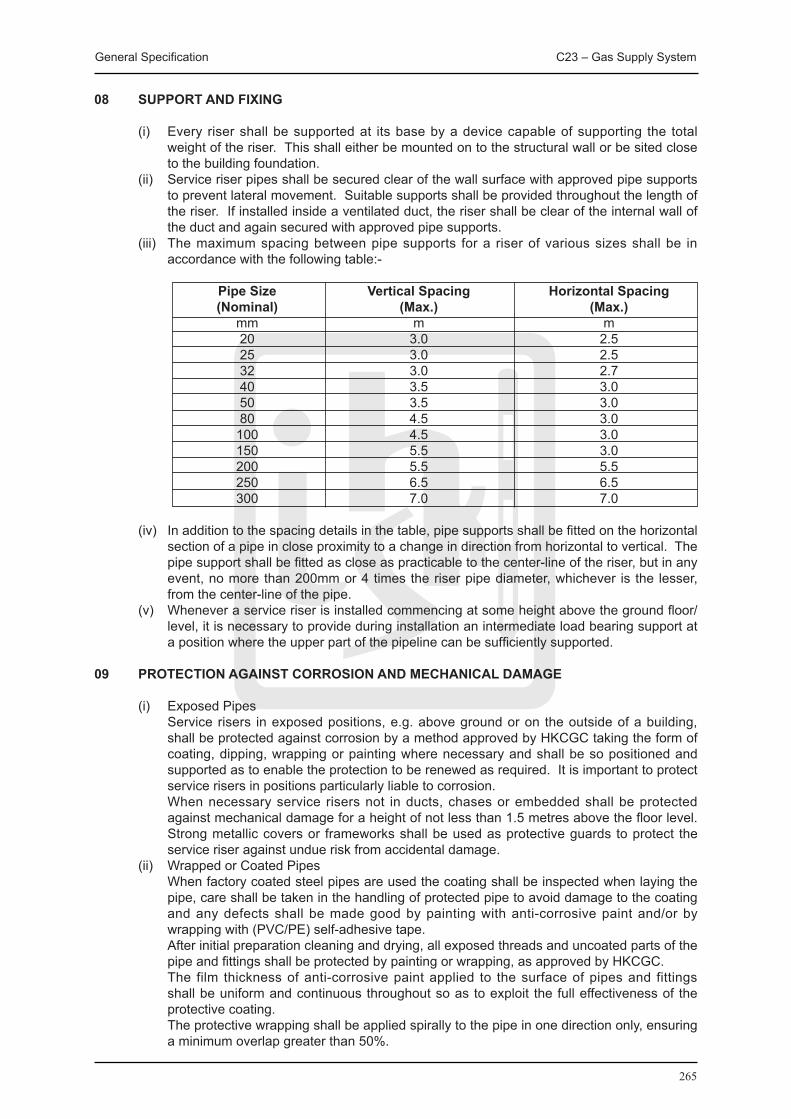
General Specification C23 – Gas Supply System
265
08 SUPPORT AND FIXING
(i) Every riser shall be supported at its base by a device capable of supporting the total weight of the riser. This shall either be mounted on to the structural wall or be sited close to the building foundation.
(ii) Service riser pipes shall be secured clear of the wall surface with approved pipe supports to prevent lateral movement. Suitable supports shall be provided throughout the length of the riser. If installed inside a ventilated duct, the riser shall be clear of the internal wall of the duct and again secured with approved pipe supports.
(iii) The maximum spacing between pipe supports for a riser of various sizes shall be in accordance with the following table:-
Pipe Size Vertical Spacing Horizontal Spacing (Nominal) (Max.) (Max.) mm m m 20 3.0 2.5 25 3.0 2.5 32 3.0 2.7 40 3.5 3.0 50 3.5 3.0 80 4.5 3.0 100 4.5 3.0 150 5.5 3.0 200 5.5 5.5 250 6.5 6.5 300 7.0 7.0
(iv) In addition to the spacing details in the table, pipe supports shall be fitted on the horizontal section of a pipe in close proximity to a change in direction from horizontal to vertical. The pipe support shall be fitted as close as practicable to the center-line of the riser, but in any event, no more than 200mm or 4 times the riser pipe diameter, whichever is the lesser, from the center-line of the pipe.
(v) Whenever a service riser is installed commencing at some height above the ground floor/level, it is necessary to provide during installation an intermediate load bearing support at a position where the upper part of the pipeline can be sufficiently supported.
09 PROTECTION AGAINST CORROSION AND MECHANICAL DAMAGE
(i) Exposed Pipes Service risers in exposed positions, e.g. above ground or on the outside of a building,
shall be protected against corrosion by a method approved by HKCGC taking the form of coating, dipping, wrapping or painting where necessary and shall be so positioned and supported as to enable the protection to be renewed as required. It is important to protect service risers in positions particularly liable to corrosion.
When necessary service risers not in ducts, chases or embedded shall be protected against mechanical damage for a height of not less than 1.5 metres above the floor level. Strong metallic covers or frameworks shall be used as protective guards to protect the service riser against undue risk from accidental damage.
(ii) Wrapped or Coated Pipes When factory coated steel pipes are used the coating shall be inspected when laying the
pipe, care shall be taken in the handling of protected pipe to avoid damage to the coating and any defects shall be made good by painting with anti-corrosive paint and/or by wrapping with (PVC/PE) self-adhesive tape.
After initial preparation cleaning and drying, all exposed threads and uncoated parts of the pipe and fittings shall be protected by painting or wrapping, as approved by HKCGC.
The film thickness of anti-corrosive paint applied to the surface of pipes and fittings shall be uniform and continuous throughout so as to exploit the full effectiveness of the protective coating.
The protective wrapping shall be applied spirally to the pipe in one direction only, ensuring a minimum overlap greater than 50%.
General Specification C23 – Gas Supply System
266
Anti-corrosion wrapping tapes used for pipe protection against corrosion shall be able to withstand a wash with 10% solution of hydrochloric or oxalic acid prior to rinsing with fresh water.
10 FINISHING AND LABELLING
(i) The Contractor shall supply and install suitable labeling for the completed Town Gas Installation including pipeworks and valves.
(ii) Service riser pipes shall be identified by means of affixing standard self-adhesive yellow marking tape with the word Towngas in English and Chinese superimposed.
(iii) A line diagram of the service supply pipework shall be displayed to enable service riser valves to be identified and located promptly in the event of an emergency.
C23.3 INSPECTION, TESTING AND COMMISSIONING
01 GENERAL
The testing of systems under the various sections of the Specification may be required to be carried out in parts, or as a whole.
The Contractor shall demonstrate to the satisfaction of the Contract Administrator or his representative that the installation or any portion thereof, which has been set to work, complies with the requirements of the specification.
The Contract Administrator shall have power to delegate his powers of inspection and test to an independent person or organization who shall be empowered to carry out the Contract Administrator functions on his behalf and whose name and standing shall have been communicated to the Contractor in writing by Contract Administrator.
The Contract Administrator shall have power to direct the Contractor to submit samples of material or specimen components to an independent testing organization for analysis, test, or evaluation. The costs of any such examination shall be met by the Contractor.
The Contract Administrator shall have the right to reject any material, apparatus or equipment which, as the result of inspections and/or tests may be found to be defective or unsatisfactory in any respect, or not in accordance with the requirements of this Specification, and to require the Contractor to repair, adjust, modify, or replace the defective item. In the case of works testing this shall be done before dispatch to site. If the defective item be adjudged by the Contract Administrator to be unsuitable for repair, adjustment or modification, then it shall be replaced by a completely new item at the expense of the Contractor.
All expenses incurred by the Contract Administrator or his authorized representative in connection with inspections or tests resulting in the rejection of the item(s) offered for inspection or test shall be charged to the Contractor or deducted from sums due to him as decided to be necessary by the Contract Administrator.
The Contractor shall be responsible for any damage caused to his work or other work due to failure of his work under test.
02 APPROVALS AND ACCEPTANCE
The works shall be tested in accordance with this Specification and to the requirements of the relevant Authorities. Proof of compliance with any Service Authority’s requirements shall be provided if requested by the Contract Administrator.
After receiving the commissioning reports the Contract Administrator shall check that the claimed results are within the allowed tolerances and shall then authorize the Contractor to proceed with the system performance tests.
The Contractor shall give the Contract Administrator not less than seven days written notice of

General Specification C23 – Gas Supply System
267
his intention to demonstrate and seek acceptance of any time or system.
All tests for the acceptance of systems or items of equipment shall be witnessed by the Contract Administrator or his appointed representative.
The Contractor shall allow for giving such notice and making adjustment’s setting up, and other preparations for testing and for the Contract Administrator or his representative’s attendance in witnessing such tests.
The Contractor shall give a minimum of fourteen days notice of his requirements for attendance by the Manufacturer of major plant items. Copies of this notice shall be sent to the Contract Administrator for his information.
03 COMPETENT PERSONNEL
The Contractor shall carry out this work using trained, experienced commissioning engineers. The commissioning Supervising Engineer shall have several years experience in the testing and commissioning of similar installations.
The Contractor’s commissioning engineer shall ensure that all commissioning work carried out by such specialist manufactures is carried out to his satisfaction and in such a way that it does not prevent his proceeding with the overall commissioning of the installation.
04 TEST EqUIPMENT
The Contractor shall supply and fix all necessary apparatus for conducting tests on the installations.
The Contractor shall submit to the Contract Administrator a list of the equipment which he proposes to use in the testing and commissioning of the services. This shall be completed with the serial numbers of all instruments and their last calibration date.
All instruments that require periodic re-calibration shall have this carried out before work is commenced. If in the opinion of the Contract Administrator, instruments should be rechecked for accuracy because of the time which has elapsed since the previous calibration, this shall be carried out at the Contractor’s expense.
Data sheets shall be submitted on each test instrument to be used, indicating the manufacturer’s name, model number, serial number, latest date of calibration, and correction factors.
If the Contractor finds that the installation of additional equipment shall facilitate the carrying out of his works, he shall allow in his estimate for the temporary installation of such equipment. He shall obtain the equipment. No such equipment shall be left in the system after completion of the testing and commissioning work without the permission of the Contract Administrator.
05 TEST CERTIFICATE
The Contractor shall allow for submitting three copies of the test certificates to the Contract Administrator bearing the signatures of the Contractor’s and the Contract Administrator’s representatives at the test.
Test certificates shall serve as a certified record that the item referred to has been shown under test to meet the requirements of this document, British Standard, Local Authority regulations, Statutes and the like, where applicable.
Test certificates shall be dated, numbered and clearly retrenched to the item tested by means of serial, chassis, or other manufacturers’ reference number permanently marked in a conspicuous manner on the item concerned.
General Specification C23 – Gas Supply System
268
In addition to the above, test certificates as may be required shall be submitted to the Statutory Authorities.
The Contractor shall submit to the Contract Administrator a complete set of data on all equipment and systems which he commissions. The submittals shall be on A3 or A4 size paper and the form which they take shall be agreed with the Contract Administrator before their submission. They shall show the design figures and the final operating values at which the systems and equipment were set by the commissioning engineer. He shall also record the settings of all controls, relays, overloads, etc.
06 SITE TESTS
Upon completion of services installations or portions of the services installations, all the completed installations or part installations including equipment shall be subjected to the tests specified in the relevant British Standards, Code of Practice and the IEE Regulations, together with such other tests as may be required by the Contract Administrator in order to prove compliance with this specification. When no relevant British Standard or Code of Practice exists or the appropriate British Standard or Code of Practice fails to specify test, tests shall be carried out to the requirements of the Contract Administrator.
Test not carried out in the presence of the Contract Administrator shall not be regarded as valid for the purpose of the Contract, unless the Contract Administrator shall have previously signified his inability to attend, and shall have authorized the Contractor to proceed with the testing process in his absence.
The Contract Administrator and his authorized representative shall have unrestricted access on or about the site of the Works at all times during the site working hours, and at other times by agreement, for the purpose of carrying out inspections or witnessing tests upon the installations.
Any defects that become apparent during tests of any part or parts of the installations, shall be rectified at the Contractor’s expense and the parts re-tested to the satisfaction of the Contract Administrator, FSD, and Buildings Department, as appropriate.
The Contractor shall keep a record of tests carried out on the installation throughout the Contract, recording the date of test, by whom tested and result, and two copies of the record shall be sent to the Contract Administrator on completion of the Contract.
Defective materials shall be clearly and permanently marked, and removed from site and kept record.
After the completion of installation and jointing and before they are put into service, they shall be subject to the tests described below:
(i) An air test for sounders shall be carried out to the completed service riser installation and to any section of the riser. The pressure test should be made before any wrapping or coating is applied to the joints of the service riser.
(ii) Due to the effects of changing ambient temperature and pressure on the test result, the duration of soundness test shall not normally exceed 15 minutes. This is particularly important with exposed pipework which should be tested at such a time when the conditions are stable.
(iii) Before commencing the test, the equipment such as pressure gauge, T-piece, and rubber tube etc. shall be checked for soundness.
(iv) Gas service risers shall be tested in the following manner: (a) All ends of the system shall be capped or otherwise suitably sealed with the exception
of one end to which a T-piece carrying a cock on one outlet and a water gauge on the other shall be fitted.
(b) Air is then pumped into the service riser pipe through the cock until a pressure not less than 11.25 kPa (45 in W.G.) or one and a half times the maximum working pressure, whichever is the greater, is registered on the pressure gauge.
(c) The cock is then shut; the test for service riser pipes will be deemed to be satisfactory if, after the expiration of an adequate period to allow for adjustment of temperature,
General Specification C23 – Gas Supply System
269
no drop in pressure is indicated after a period of 5 minutes (based on a permitted leak rate of 1.4 dm3/h) for installations of pipe volume smaller than 0.5m3.
(d) The test period for installations of pipe volume in excess of 0.5m3 shall be 15 minutes.
(v) If a drop in pressure is registered, the leak(s) shall be tracked by leak detection fluid and rectified accordingly. After rectification, pressure test shall be repeated to ensure the soundness of the system.
After connecting the system to the underground gas supply, the prefabricated final connection shall be tested for leakage using a suitable leak detection fluid.
(vi) The method of gas meter test shall be as follows:- (a) Cap or suitably seal the inlet and all outlets of the system with the exception of one,
which shall be fitted with a T-piece carrying a cock on one branch and a water gauge on the other.
(b) Where the pipework to be tested includes a meter regulator fitted with a pressure test point on its inlet, connect this temporarily to the test point on the outlet of the meter.
(c) Pump air into the installation pipe system through the cock on the T-piece until a pressure of 3 kPa (12 in W.G.) or one and a half times the maximum working pressure, whichever is the greater is registered on the pressure gauge.
(d) Shut the cock and allow 1 minute for temperature stabilization. If no fall in pressure is registered on the pressure gauge in the following 2 minutes, the system may be considered satisfactory. If a fall is registered, the fault shall be traced and rectified.
(e) After connecting the system to the gas supply, test any joints not already tested in this connecting pipework with leak detection fluid, using the available gas pressure; this includes pipework connected to the inlet of a meter regulator which does not have a pressure test point at its inlet.
07 COMMISSIONING
Following the satisfactory conclusion of final inspections and tests on completed sections of the Works, the Contractor shall duly commission each section of the electrical and mechanical installations and leave them in full working order. The term “Commissioning” shall be deemed to include:
(i) checking of system of entire installation performance, making all required adjustments to valves, until all performance requirements are met.
(ii) setting of electrical protective devices and systems, where relevant, in accordance with the directions of the Contract Administrator or, failing such directions, in accordance with sound engineering practice.
(iii) the starting up of all electrical and mechanical equipment. (iv) the verification of the performance of all such installation by the carrying out, where
required, of further tests and the making of all necessary adjustments so as to obtain optimum performance.
Mere compliance with the requirements of this section of the Specification shall not, by itself, in any way relieve the Contractor of any of his obligations under the Contract.
No approval given by the Contract Administrator in connection with the commissioning process, whether by way of approval of procedures carried out or proposed, or approval of results obtained shall in any way relieve the Contractor of the contractual and statutory obligation to ensure that all connections and adjustments are made correctly and that the installations are handed over in a completely safe and satisfactory condition.
The Contract Administrator shall have power to appoint an independent Commissioning Engineer to act on his behalf in the control of all activities relating to the Contractor’s commissioning process, and in such matter the said Commissioning Engineer shall be deemed to be an authorized representative of the Contract Administrator.
No connections or adjustments shall be made to plant or equipment which has already been commissioned and set to work, except with the prior consent of the Contract Administrator.
No plant or equipment shall be charged, energized or operated without the prior approval of
General Specification C23 – Gas Supply System
270
the Contract Administrator. All applicable test certificates shall have been submitted to the Contract Administrator before such approval shall be given.
All commissioning procedures shall be carried out in a safe and satisfactory manner, and to the complete satisfaction of the Contract Administrator.
Following completion of commissioning, each item of equipment or where several items of equipment are interdependent, the complete plant shall operate continuously and satisfactorily under normal operating conditions for a period of 72 hours without defect of any kind. In the event of any defect or mal-operation becoming apparent during this period the Contractor shall forthwith determine the cause and rectify it by means of repair, replacement, adjustment or modification and the reliability run shall be re-commenced. All materials, equipment and labour required to locate and rectify any such defect shall be provided by the Contractor at his own expense.
No plant or installation shall be considered as complete until the prescribed commissioning procedures have been satisfactorily carried out and the reliability run has been completed without untoward incident.
The Contract Administrator shall have power to require that the whole of the plant, equipment and installations, or selected parts thereof, be re-inspected and, if necessary, re-tested immediately before the end of the contractual maintenance period, and the Contractor shall be responsible for making all necessary arrangements with the Contract Administrator.
08 COMMISSIONING RECORDS
Immediately upon completion of the Commissioning work the Contractor shall forward to the Contract Administrator the following completed record sheets:
(i) Schedule of all regulating valves, flow rates and settings. (ii) Schedule of electrical equipment application, types, full load currents and overload
settings.
The Contractor shall forward Record Sheets for all other items of plant or electrical systems, supplied and installed under the conditions set out in these documents, to the Contract Administrator.
09 TEST NOTICES
The Contractor shall ensure that all formalities in connection with Test Notices, Agreement and Application for Supply forms etc., are complied with and that all such documents requiring the Clients signatures are forwarded to the Contract Administrator in ample time.
Any charges incurred due to re-connections, re-visits etc., by Supply Authorities, Government Authorities, or any other officials shall be the responsibility of the Contractor.
C23.4 OPERATION AND MAINTENANCE (O&M) MANUAL AND USER MANUAL
01 GENERAL
The Contractor shall provide two types of manuals to the Contract Administrator with all changes made to the installation during the course of the Contract suitably incorporated.
The O&M Manual is for use by the maintenance agent of the completed installation. It shall contain detailed technical information covering both operation and maintenance aspects of the installation.
The User Manual seeks to give users of the completed installation an overview of the essential information of the installation. The contents of the manual should be concise and succinct for ease of comprehension by people with a non-technical background.

General Specification C23 – Gas Supply System
271
02 PRESENTATION
All manuals shall be written in English, unless otherwise specified. The text of descriptive parts shall be kept concise while at the same time ensure completeness. Diagrammatic materials shall also be supported by comprehensive descriptions. The Contract Administrator’s approval shall be obtained on this at the draft manual.
03 STRUCTURE AND CONTENTS OF O&M MANUAL
The detailed requirements, structure and contents of the O&M Manual shall be as specified elsewhere in the Contract and shall include the following information under separate sections where appropriate:
(i) Project Information include: Project title, site address, contract no., contract title, main contractor/lift contractor name,
address, contact persons and their telephone/fax nos., contract commencement date, substantial completion date and end date of maintenance period.
(ii) System Description (a) Type(s) of system(s) and equipment installed; (b) Design criteria, design data and parameters; (c) Locations of the system and major equipment, and what they serve; (d) Description of operation and functions of the system and equipment; and (e) General operating conditions, expected performance and energy and resources
consumption where applicable. (iii) List of Installed Equipment Schedule of all items of equipment and plant stating the location, name, model no.,
manufacturer’s serial or reference no., manufacturer’s design duties and data. (iv) Spare Parts and Special Tools Lists (a) List of Spare Parts supplied by the Contractors including item descriptions, supplied
quantities, model nos., manufacturer’s serial or reference nos. and storage locations. (b) Recommended Spare Parts List and Special Tools List including Manufacturers’/
suppliers’ recommendations for spare parts and special tools with item description, unit rate, recommended stock quantities as well as the agents for the spare parts and special tools.
(v) Manufacturers’ Certificates/Guarantees (a) Manufacturers’ certificates such as factory test certificates, laboratory test reports and
guarantees and any others where required for the equipment and plants, etc. (b) Originals of Statutory Inspection Certificate for various installations. Testing records & commissioning data (other than the types prescribed above), which are
required under the Contract such as the T&C procedures, etc to verify the compliance of the BS/E&M system’s/equipment’s performance with the contract requirements, are checked and endorsed separately by the Contract Administrator and do not form part of the O&M manuals.
(vi) Safety Precautions for Operation and Maintenance State, where applicable, hazard warnings and safety precautions of which the operation
and maintenance staff need to be aware: (a) mandatory requirements relating to safety; (b) known hazards against which protection measures shall be taken; and (c) known features or operational characteristics of the installed equipment or systems
which may cause hazard and the related safety precautions. (vii) Operation Instructions Instructions for the safe and efficient operation, under both normal and emergency
conditions, of the installed system which shall comprise: (a) an outline of the operating mode; (b) control logic and data (sequence, effect, limits of capability, modes and set points); (c) procedures and sequences for start-up and shut-down; (d) interlocks between equipment/system; (e) calling on of stand-by equipment; (f) precautions necessary to overcome known hazards; (g) means by which any potentially hazardous equipment can be made safe; (h) estimation of energy consumption and energy costs;
General Specification C23 – Gas Supply System
272
(i) forms for recording plant running hours, energy consumption and energy costs; and (j) operating data such as running current, operating pressure, operating flow rates, etc. (viii) Maintenance instructions Manufacturers’ and the Contractor ’s recommendations and instructions for the
maintenance of the installed equipment. Clear distinction should be made between planned tasks (preventive maintenance) and fault-repair tasks (corrective maintenance). Instructions shall be given on each of the following, as appropriate:
(a) nature of deterioration, and the defects to be looked for; (b) isolation and return to service of plant and equipment; (c) dismantling and reassembly; (d) replacement of components and assemblies; (e) dealing with hazards which may arise during maintenance; (f) adjustments, calibration and testing; and (g) special tools, test equipment and ancillary services. (ix) Maintenance schedules Proposed maintenance schedules for all the preventive maintenance tasks identified
above. The schedules shall be based on both manufacturers’ recommendations and other authoritative sources (e.g. statutory or mandatory requirements) and should include:
(a) routine servicing; (b) inspections; (c) tests and examinations; (d) adjustments; (e) calibration; and (f) overhaul. The frequency of each task may be expressed as specific time intervals, running hours
or number of completed operations as appropriate. Collectively, the schedules will form a complete maintenance cycle, repeated throughout the whole working life of the installation.
(x) Drawing Lists (a) A complete list of as-built drawings identified with drawing number/reference; (b) A complete list of manufacturers’ shop drawings with drawing number/reference,
where applicable; and (c) A brief description of CD-ROM for these drawings. (xi) Technical Literatures A complete set of manufacturers’ literatures for all the plant and equipment installed in the
system. The contents of these literatures shall cover the following areas where applicable: (a) description of equipment with model numbers highlighted; (b) performance - behavioural characteristics of the equipment; (c) applications - suitability for use; (d) factory/laboratory test reports, detailed drawings, circuit diagrams; (e) methods of operation and control; (f) operation instructions; (g) cleaning and maintenance requirements; (h) plants, materials and space required for maintenance; (i) protective measures and safety precautions for operation and maintenance; and (j) part lists. (xii) Contact addresses and telephone numbers of suppliers of major equipment.
04 STRUCTURE AND CONTENTS OF USER MANUAL
The detailed requirements, structure and contents of the User Manual shall include, where applicable, the following information:
(i) Project Information This shall include: Project title, site address, contract no., contract title, contract commencement date,
substantial completion date and end date of Maintenance Period. (ii) System Description (a) Type(s) of system(s) and equipment installed, and their purposes; (b) Locations of major plant rooms and riser ducts; (c) Brief description of the operation and functions of the systems and equipment; and
General Specification C23 – Gas Supply System
273
(d) Listing of set points which can be adjusted by the user to suit their operation needs. (iii) Schedule of Major Plant Rooms and Installed Equipment (a) Schedule of major plant rooms and riser ducts including their locations; and (b) Schedule of major equipment and plants including their locations and serving areas. (iv) Safety Precautions for Operation Any safety precautions and warnings signals that the users shall be aware of in the daily
operation of the various systems and equipment in the installation including: (a) mandatory requirements relating to safety; (b) features or operational characteristics of the installed systems or equipment which
may cause hazard and the related safety precautions; (c) protective measures and safety precautions for operation; and (d) list of warning signals and the related meanings that the user shall be aware of and
the actions to be taken. (v) Operation Instructions Instructions for the safe and efficient operation, under both normal and emergency
conditions, of the installed system which shall comprise: (a) an outline of the operating mode; (b) step by step operation instructions for systems and equipment that are to be operated
by the user, including at least procedures for start-up and shut-down; (c) means by which any potentially hazardous situation can be made safe; and (d) cleaning and basic maintenance procedures. (vi) List of Statutory Periodic Inspections and Tests A schedule of periodic inspections and tests that owner and/or user of the installation have
to arrange to achieve compliance with the requirements stipulated in the relevant Laws of Hong Kong. The frequency of such inspections and tests shall be expressed in specific time intervals.
(vii) Drawings A set of selected as-built drawings which shall be able to illustrate to the user the general
layout of the completed installation. (viii) Photographs A set of photographs with suitable captions to illustrate to the user the appearance and
locations of devices which require their setting and operation.

274

275
C24 LiftInstallationSystem
General Specification C24 – Lift Installation System
276
C24 LIFT INSTALLATION SYSTEM
C24.1 GENERAL REqUIREMENTS
The works to be carried out in accordance with this Specification shall include the whole of the design, installation and supply of all materials necessary to form a complete installation including any necessary tests & commissioning and maintenance as prescribed and all other incidental sundry components together with the necessary labour for installing such components, for the proper operation of the installation.
01 PROGRAMME OF WORKS
The Lift Contractor shall submit to the Contract Administrator a detailed programme of the works within 4 weeks from the acceptance of his Tender showing the intended method, stages and order of work execution in coordination with the building construction programme, together with the duration he estimated for each and every stage of the works. The programme shall include at least the following:
(i) Dates for the placement of orders for equipment and materials; (ii) Expected completion dates for builder’s works, i.e. when work site needs to be ready; (iii) Delivery dates of equipment and materials to Site; (iv) Dates of commencement and completion of every stage of the works in line with the
building construction programme, i.e. each floor level and/or zone area; (v) Dates of documents/drawings submissions to relevant Government departments to obtain
the necessary approvals; (vi) Dates of requirement of temporary facilities necessary for testing & commissioning, e.g.
electricity supply, water and town gas; (vii) Dates of completion, testing and commissioning; and (viii) Short term programmes showing the detailed work schedules of coming weeks and
months shall also be provided to the Contract Administrator. Programmes shall be regularly updated to reflect the actual progress and to meet the Lift Contractor’s obligations under the Contract.
In addition, detailed submission schedules for installation drawings, equipment and testing and commissioning shall be submitted to the Contract Administrator for approval. The formats and information to be included in the schedules shall be as required by the Contract Administrator.
02 BUILDER’S WORK
The following builder’s work in connection with lift, escalator, passenger conveyor, powered vertical lifting platform and stairlift installation as shown in the Drawings will be carried out as part of the building works by the Main Contractor at the expense of the Employer provided that the Lift Contractor has submitted full details of such requirements within a reasonable time to the Contract Administrator for approval, so that due consideration may be given before the Main Contractor commences the building works in accordance with the building programme in the areas concerned:
(i) Construction of the lift well and enclosures with pit and machine room in accordance with the Drawings;
(ii) Construction of the escalator/passenger conveyor pits, wells and concrete supporting beams in accordance with the Drawings;
(iii) Provision of necessary holes, chases, openings, plinths, vents; (iv) Provision and fixing steel joists and scaffoldings required for the hoisting of lift/escalator/
passenger conveyor machinery and accessories; (v) Provision of concrete fill and/or grouting in for architraves, landing door frames, sills and
associated safety guard, etc.; (vi) Provision of structural steelwork for lift machinery in lift machine room; (vii) For multiple wells, provision of shaft dividing steelwork for supporting guide brackets, etc.
and inter-well screens; (viii) Provision of openings with adequate size in the floor on both landings of escalator/
passenger conveyor; (ix) Provision of concrete supporting beams at both landings and the intermediate support if
General Specification C24 – Lift Installation System
277
required by escalators with a large vertical rise; (x) Provision of drain outlet and/or sump pit in lift/escalator pit, where specified; (xi) Construction of the lift enclosure with pit for powered vertical lifting platform in accordance
with the Drawings; (xii) Provision of opening to open air for ventilation of the lift shaft for powered vertical lifting
platform, where specified; and (xiii) Provision of pit/ramp and drainage for powered vertical lifting platform, where specified.
After obtaining the said approval of the Contract Administrator, the Lift Contractor is required to mark out at the relevant locations of the Site the exact positions and sizes of all such works and to provide detailed information of such works to the Main Contractor to facilitate him to carry out the builder’s work as the works proceed.
All ‘cutting-away’ and ‘making-good’ as required to facilitate the Lift Contractor’s works will be carried out by the Main Contractor, except for minor provisions required for the fixing of screws, raw plugs, redhead bolts, etc. which shall be carried out by the Lift Contractor. The Lift Contractor shall mark out on Site and/or supply drawings of all cutting-away to the Main Contractor within a reasonable time.
All expenses properly incurred and losses suffered by the Employer as a result of the Lift Contractor’s failure to comply with the above requirements are recoverable by the Employer from the Lift Contractor.
The Lift Contractor shall ensure that such works are essential for the execution of the works. In the event that any of such works is proved to be non-essential, unnecessary and/or abortive, the Lift Contractor shall bear the full cost of such works including but not limited to any unnecessary or incorrect cutting-away and making-good and shall reimburse the Employer for all cost incurred in this connection.
Upon completion of the builder’s works by the Main Contractor, the Lift Contractor shall forthwith check and examine that all builder’s works so executed have been completed in accordance with his requirements. If at any time it becomes apparent to the Lift Contractor that any builder’s works completed by the Main Contractor does not comply with his requirements in any respect whatsoever, the Lift Contractor shall forthwith give notice in writing to the Contract Administrator and specify in details the extents and effects of such non-compliance in that notice. The Lift Contractor is deemed to have satisfied with the builder’s works after a period of 14 days from the date of completion of the builder’s works if the above notice is not served to the Contract Administrator within such period. All additional expenditure properly incurred and all loss suffered in this connection by the Employer in having such works re-executed and rectified shall be recoverable by the Employer from the Lift Contractor.
03 COORDINATION OF CONTRACT WORKS
The Lift Contractor shall coordinate and cooperate the works with those works of the Main Contractor and any other contractors and sub-contractors at all times in order to achieve efficient workflow on Site.
The Lift Contractor shall note that the Drawings supplied to him only indicate the approximate locations of the works. He shall make any modification reasonably required of his programme, work sequence and physical deployment of his works to suit the outcome of work coordination or as necessary and ensure that all cleaning, adjustment, test and control points are readily accessible while keeping the number of loops, cross-overs and the like to a minimum.
The Lift Contractor shall pay particular attention to the building works programme and
shall plan, coordinate and programme his works to suit and adhere to the building works in accordance with the building programme.
04 SITE SUPERVISION
The Lift Contractor shall keep on the Site a competent and technically qualified site supervisor

General Specification C24 – Lift Installation System
278
to control, supervise and manage all the works on site.
The site supervisor shall be technically competent and have adequate site experience for the works.
Approval by the Contract Administrator shall be obtained prior to the posting of the supervisor on Site. The Lift Contractor shall immediately replace any site supervisor whose experience, skill or competency is, in the opinion of the Contract Administrator, found to be inadequate for the particular work.
05 SAMPLE BOARD
Within 6 weeks of the acceptance of his Tender and prior to the commencement of works, the Lift Contractor shall submit to the Contract Administrator for approval in good time a sample board of essential components proposed to be used in the Contract. A list shall also be affixed on the sample board to show the item description, make and brand, country of origin and locations of installation. Upon approval of all items, the Contract Administrator will endorse the list on the sample board and the Lift Contractor shall deliver the board to the site office for reference.
The following items shall be included in the sample board as a minimum. Additional items may be required by the Contract Administrator and/or specified in the Particular Specification.
(i) Electrical and mechanical accessories; (ii) Finishing materials; and (iii) Colour chart.
06 RECORD OF MATERIALS DELIVERY
All materials delivered to Site shall be accurately listed and recorded in the site record books maintained by the representatives of the Contract Administrator on Site. Such materials and equipment shall not be removed from Site without the approval of the Contract Administrator in writing.
07 PROTECTION OF MATERIALS AND EqUIPMENT
The Lift Contractor shall be responsible for the safe custody of all materials and equipment as stored or installed by him until finally inspected, tested and accepted. In addition, the Lift Contractor shall protect all works against theft, fire, damage or inclement weather and carefully store all materials and equipment received on Site but not yet installed in a safe and secure place unless otherwise specified.
08 DISABLED LIFT
(i) Disabled lift for the building shall have all provisions required for disabled lift. (ii) Essential lift controls, alarm and switches, but not necessarily excluding other controls,
shall not be lower than 900mm or higher than 1200mm above finished floor level. (iii) Signage shall be provided to indicate the lift is for disabled use. (iv) Voice floor messages (both Chinese and English) shall be provided. (v) All landing/car control buttons shall be micro-movement type with braille code indication. (vi) The secondary car operating panel provided shall be at not lower than 900mm but not
higher than 1200mm above finished floor level.
09 FIREMAN’S LIFT
(i) Fireman’s lift for the building shall have all provisions required by FSD/EMSD for fireman’s lift.
(ii) Fireman’s lifts provided shall fully comply with FSD’s/EMSD’s requirements and shall further satisfy the following conditions:
(a) Lift shaft openings shall be provided with automatic self-closing fire-resisting doors.

General Specification C24 – Lift Installation System
279
(b) It shall be provided with a suitable control switch at terminal floor level to enable the Fire Services Department to gain immediate control over the lift and return it to terminal floor. When a Fireman’s Switch is operated the lift shall decelerate and stop at the next possible landing floor. The car and landing doors shall remain closed and the lift shall return to the terminal floor without stopping for car or landing calls. Sole control of the lift shall then be affected in the car control station.
(c) The speed of the lift car shall be such that it shall reach the topmost discharge point of the building in not more than 1 minute, calculating from the time when the lift doors on the lowest discharge point are completely closed to the time when the lift doors at the topmost discharge point start to open.
(d) It shall be suitably indicated by the words ‘FIREMAN’S LIFT’ in English and Chinese at the terminal floor.
(iii) Fireman’s switch shall be provided by the Lift Contractor and shall be of a type which does not require a key for operation. Where a toggle switch is used the ‘down’ position shall correspond to the ‘on’ position. The fireman’s switch shall be located adjacent to the lift opening at the terminal floor and shall be at a height of approximately 2m above the floor level. For easy identification of fireman’s lift which conform to FSD’s/EMSD’s requirements, a red and white diagonal striped backing shall be provided behind the glass of the fireman’s switch.
(iv) A permanent notice of prominent size indicating the floors served shall be provided by the Lift Contractor and displayed adjacent to the fireman’s lift at the terminal floor. The notice shall be made of laminated plastic sheet or other approved material with red letters on white background in English. Details of the notice shall be submitted to the Contract Administrator for approval prior to fabrication.
(v) The doors of a fireman’s lift opening onto a refuge floor shall be locked at all times until automatically released on actuation of the fireman’s switch.
C24.2 MATERIALS AND EqUIPMENT SPECIFICATION
C24.2.1 GENERAL
01 MATERIALS AND EqUIPMENT
All materials, equipment and installation works shall be carried out by adoption of the best available quality materials and workmanship and shall, where applicable, comply with the latest edition of the appropriate standards and/or codes of practice and as specified in this General Specification. This requirement shall be deemed to include all amendments to these standards and codes up to the date of tendering.
Selection of materials and equipment shall be based on this General Specification, the Particular Specification and the technical data contained in the Drawings. Where different components of equipment are interconnected to form a complete system, their characteristics of performance and capacities shall match in order to ensure efficient, economical, safe, reliable and sound operation of the complete system.
02 WORKMANSHIP
Works shall be carried out in such a manner as to comply with all relevant ordinances, regulations and codes of practices as listed in this General Specification together with any amendments made thereto.
Proper tools shall be used for the Works. The installation works shall be in line with the good practice accepted by the local industry and in compliance with this General Specification, the Particular Specification and the Drawings.
All tradesmen shall be experienced in the trade and the Works carried out shall be consistent with good practice in Hong Kong and to the satisfaction of the Contract Administrator.
General Specification C24 – Lift Installation System
280
C24.2.2 GUIDES AND FIXING
01 STEEL GUIDES SHALL BE USED
Rigid steel guides shall be used for guiding lift cars and counterweights throughout their travel.
02 REqUIREMENTS
(i) The strength of the guides, their attachments and joints shall comply with EN 81-1:1998 and ISO 7465:2001 and be sufficient to withstand the forces imposed due to the operation of the safety gear and deflection due to uneven loading of the car; and
(ii) The guides shall have machined surfaces for rated speeds exceeding 0.4 m/s.
03 GUIDE BRACKETS
Guide brackets shall be provided at suitable intervals and shall be embedded into the walls enclosing the lift well or fixed to such walls by one of the following methods:
(i) Self-drilling anchor bolts - this method shall be used as the standard practice for fixing guide rail brackets in reinforced concrete walls of 100 mm thick or more; and
(ii) Bolts grouted and embedded into the walls - this method shall only be used in special conditions, e.g. brick walled lift wells, or reinforced walls of less than 100 mm thickness, or as and when specified in the Particular Specification or by the Contract Administrator.
Wood or fibre blocks or plugs shall not be used for securing any guide brackets.
When method (b) above is used, the Contractor shall ensure that the holes reserved by the Building Contractor for the bolts are properly and correctly positioned. The Contractor shall be responsible for any subsequent cutting of the holes afterwards if these holes are displaced.
C24.2.3 BUFFERS
01 BUFFERS
Buffers shall be provided at the bottom limit of travel for cars and counterweights.
02 ENERGY ACCUMULATION TYPE BUFFERS
Energy accumulation type buffers shall only be used if the rated speed of the lift does not exceed 1 m/s.
03 ENERGY ACCUMULATION TYPE BUFFERS WITH BUFFERED RETURN MOVEMENT
Energy accumulation type buffers with buffered return movement shall only be used if the rated speed of the lift does not exceed 1.6 m/s.
04 ENERGY DISSIPATION TYPE BUFFERS
Energy dissipation type buffers may be used whatever the rated speed of the lift.
C24.2.4 COUNTERWEIGHTS
01 GENERAL REqUIREMENTS
The counterweight shall be of metal and constructed from multiple sections, contained and secured within a steel frame, and shall equal to the weight of the complete car plus approximately 40% to 45% of the Contract Load.
02 GUIDE SHOES TO BE PROVIDED
At least, four guide shoes, capable of being easily renewed or having renewable linings shall

General Specification C24 – Lift Installation System
281
be provided on the counterweight.
03 COUNTERWEIGHT PULLEYS
If there are pulleys on the counterweight they shall incorporate devices to avoid: (i) the suspension ropes, if slack, leaving the grooves; and (ii) the introduction of objects between ropes and grooves.
C24.2.5 SUSPENSION
01 SUSPENSION ROPES
Cars and counterweights shall be suspended from steel wire ropes of best quality, the size and number being in accordance with EN 12385-5:2002. The factor of safety for the suspension ropes shall be not less than 12 in the case of traction drive with three ropes or more.
02 NUMBER OF ROPES AND SAFETY FACTOR
The minimum number of suspension ropes shall be two and they shall be independent. Where reeving is used the number to take into account is that of the ropes and not the falls.
The safety factor of the suspension ropes shall be at least: (i) 12 in the case of traction drive with three ropes or more; (ii) 16 in the case of traction drive with two ropes; and (iii) 12 in the case of drum drive.
03 MINIMUM NOMINAL DIAMETER
The nominal diameter of the ropes shall be at least 8 mm.
04 COMPENSATING ROPE
For travels over 30 m, the Contractor shall provide compensation for hoisting ropes. For speeds of 2.5 m/s or below, quiet operating chains or similar devices may be used as the means of compensation. For speeds above 2.5 m/s, compensating ropes with tensioning pulleys shall be provided.
C24.2.6 TERMINAL STOPPING AND FINAL LIMIT SWITCHES
01 NORMAL TERMINAL STOPPING AND FINAL LIMIT SWITCHES TO BE PROVIDED
Each lift shall be provided with normal terminal stopping switches and final limit switches. They shall be positively operated by the movement of the car. These switches shall either be mounted on the car frame or in the lift well.
02 FINAL LIMIT SWITCHES
The final limit switches shall: (i) For single or two speed lifts either, (a) Open directly by mechanical separation of the circuits feeding the motor and brake,
and provisions shall be made so that the motor cannot feed the brake solenoid; or (b) Open, by an electrical safety device, the circuit directly supplying the coils of the two
contactors, the contacts of which are in series in the circuits supplying the motor and brake.
(ii) In the case of D.C. variable voltage or A.C. variable speed lifts, cause the rapid stopping of the machine.

General Specification C24 – Lift Installation System
282
C24.2.7 GUARDING
01 GENERAL REqUIREMENTS
All dangerous parts shall be effectively guarded. Where applicable, components shall be designed to be inherently safe, obviating the need for external or removable guards.
02 PARTITION IN LIFT WELL
Where two or more lifts are installed in a common lift well, the Building Contractor will provide dividing beam and inter well rigid metal screen to separate each lift from an adjacent lift or its counterweight. The Contractor shall coordinate with the Building Contractor and to check and ensure that the height of the metal screen as provided complies with the following:
(i) Where the horizontal distance between the edge of the roof of a car and an adjacent car or its counterweight is 0.3 m or more, the metal screen shall be erected from the bottom of the lift pit to a minimum height of 2.5 m and across the whole depth of the lift well; and
(ii) Where the horizontal distance between the edge of the roof of a car and an adjacent car or its counterweight is less than 0.3 m, the metal screen shall be erected from the lift pit to the FULL height of the lift well and across the whole depth of the lift well.
03 COUNTERWEIGHT
Counterweights shall be guarded by means of a rigid metal screen extending from a position 0.30 m above the lift pit floor to a position at least 2.50 m above the lift pit floor.
C24.2.8 CAR FRAMES
01 GENERAL REqUIREMENTS
Every lift car body shall be carried in a steel car frame sufficiently rigid to withstand the operation of the safety-gear without permanent deformation of the car frame.
The deflection of the members carrying the platform shall not exceed 1/1000 of their span under static conditions with the rated load evenly distributed over the platform.
At least four renewable guide shoes, or guide shoes with renewable linings, or sets of guide rollers shall be provided, two at the top and two at the bottom of the car frame.
02 SUPPORTING FRAME FOR GOODS LIFT IN MARKETS AND ABATTOIRS
The bottom-supporting frame for car body shall be made of hot-dip galvanised mild steel.
C24.2.9 CAR ENCLOSURES
01 NON-COMBUSTIBLE MATERIALS TO BE USED
Lift cars, excluding linings, shall be constructed of non-combustible materials.
02 CAR SHALL BE COMPLETELY ENCLOSED
The car of every lift shall be completely enclosed by solid walls, floor and roof and shall, save for any opening affording normal access of users thereto or for ventilation apertures or as provided in Clause C8.12, not have any openings or open work panels in the sides. The interior clear height of the car, i.e. height between the finished floor level and the underside of the false ceiling, shall be not less than 2.4 m.
03 PLATFORM LOADING
Car platforms shall be of framed construction. Platforms for passenger lift cars shall be designed on the basis of rated load, this being evenly distributed. Platforms for goods lift car

General Specification C24 – Lift Installation System
283
shall be designed to suit the particular conditions of loading.
04 INTERNAL CONSTRUCTION OF PASSENGER LIFT CAR
Unless otherwise specified in the Particular Specification and/or on the Drawings, passenger lift car enclosure shall be of steel with 4mm studded rubber floor to colour and pattern as approved by the Contract Administrator. The whole of the internal face of the car shall be of 1.5 mm thick hairline stainless steel sheet with etched pattern as approved by the Contract Administrator. A stainless steel handrail shall be provided on three sides of the lift car, extended to within 150 mm of all corners and a stainless steel skirting panel approximately 100 mm deep shall be provided. Hairline finished stainless steel false ceiling with concealed fluorescent luminaires and ventilating fan complete with metal ceiling diffuser shall be provided. The layout of the false ceiling and lighting fittings shall be subject to the approval by the Contract Administrator. The fan shall be of quiet running type having a noise level not greater than 55 dBA when measured at a distance of 1 m from the fan and it shall be capable of handling at least 20 air changes per hour of lift car volume, with car doors closed. The effective area of ventilation apertures situated in the upper part of the car shall be at least 1% of the available car area, and the same applies for any apertures in the lower part of the car. The car ventilation fan shall be switched off within a period which shall be adjustable from 5 to 15 minutes after the last registered call is answered.
05 CAR ILLUMINATION
Unless otherwise specified, every lift car shall be adequately illuminated by a minimum of two energy efficient T5 electric fluorescent luminaires with separate electronic ballast. The illumination level shall not be less than 150 lux on the lift floor level.
06 EMERGENCY LIGHTING
Every lift car shall be provided with emergency lighting operated by a rechargeable battery supply. The lighting shall be automatically switched on in the event of failure of normal power supply to the lift. One of the fluorescent luminaires as specified in car illumination shall be self-maintained emergency type with rechargeable batteries having a capacity sufficient to maintain the lighting for two hours upon failure of the normal lighting supply.
C24.2.10 CAR AND LANDING DOORS
01 GENERAL REqUIREMENTS
Each car entrance shall be provided with an imperforated car door which shall extend the full height and width of the car opening. The top track of the door shall not obstruct the car entrance.
All landing openings in lift well enclosures shall be protected by imperforated doors which shall extend the full height and width of the landing opening. The top track of landing door shall not obstruct the entrance to the lift car. Every such door shall have an F.R.P. of not less than one hour.
Where lift landings are not isolated by fire resisting enclosures or lifts that are completely surrounded by stairwells (as stipulated in paragraph 11.2 of the Codes of Practice for Fire Resisting Construction 1996 issued by the Buildings Department), the Contractor shall provide lift doors that are constructed to satisfy both the criteria for integrity and insulation in accordance with BS 476 Part 20:1987 & Part 22:1987 unless otherwise specified.
Any projections on or recesses in the exposed parts of the car doors or landing doors shall be kept to a minimum in order to avoid finger trapping between sliding parts of the door and any fixed part of the car or landing entrance.
The clearance between panels or between panels and any fixed part of the car or landing entrance shall not exceed 6 mm.
General Specification C24 – Lift Installation System
284
Sliding car and landing doors shall be guided on door tracks and sills for the full travel of the doors. The distance between the car and landing sills shall not exceed 35 mm.
The clear height of all entrances on car and landings shall not be less than 2 m.
02 PASSENGER LIFT
Unless otherwise specified in the Particular Specification, the doors for passenger lifts shall be of metal construction, and the internal face of the car door shall be lined the same as the car. The doors shall be two panels, centre opening with automatic power opening and closing unless otherwise specified.
03 DOOR OPERATOR
The door operator shall open and close the car and landing doors in a safe, smooth and quiet manner and shall be able to achieve the door operating time as specified in the Particular Specification. The maximum closing force and kinetic energy shall comply with the requirements stipulated in the Code of Practice on the Design and Construction of Lifts and Escalators issued by Electrical and Mechanical Services Department. The door motor and drive shall be of AC motor with variable voltage variable frequency (VVVF) control unless otherwise specified in the Particular Specification. Other proven types of door motor and drive may also be used subject to the approval by the Contract Administrator.
C24.2.11 CAR CAPACITY AND LOADING
01 PASSENGER LIFT
The available car area, rated load and number of passengers shall be determined from EN 81-1:1998 and EN 81-2:1998.
C24.2.12 SAFETY GEAR AND OVERSPEED GOVERNOR
01 PROVISION OF SAFETY GEAR
Every lift other than a service lift shall be provided with a safety gear capable of operating only in the downward direction and capable of stopping a fully laden car, at the tripping speed of the overspeed governor, even if the suspension devices break, by gripping the guides and holding the car there. If accessible spaces do exist underneath the counterweight, the counterweight, as well as the car, shall be provided with safety gears.
02 REqUIREMENTS OF SAFETY GEAR
Safety gears shall comply with the following general requirements: (i) The release of the safety gear on the car (or the counterweight) shall only be possible by
raising the car (or the counterweight); (ii) Each safety gear shall be tripped by its own overspeed governor; (iii) The operation of the safety gear shall not cause the car platform to slope at more than 1
in 20 to the horizontal; (iv) Vibration of the car shall not in any case cause a safety gear to operate; and (v) The tripping of safety gears by devices which operate electrically, hydraulically or
pneumatically is forbidden.
03 TYPES OF SAFETY GEAR
Car safety gear shall be of the progressive type if the rated lift speed exceeds 1 m/s. It shall be of:
(i) the instantaneous type with buffered effect if the rated lift speed does not exceed 1 m/s; or (ii) the instantaneous type if the rated lift speed does not exceed 0.63 m/s. The safety gear
of the counterweight shall be of the progressive type if the rated speed exceeds 1m/s, otherwise the safety gear may be of the instantaneous type.

General Specification C24 – Lift Installation System
285
04 OVERSPEED GOVERNOR
Overspeed governor shall be of the centrifugal type which shall operate the safety gear at a speed at least equal to 115% of the rated speed and in accordance with EN 81-1:1998. The means for adjusting the overspeed governor shall be sealed after setting the tripping speed.
05 OPERATION OF THE OVERSPEED GOVERNOR
The motor control and brake-control circuits shall be opened before or at the same time as the governor trips and cause the lift motor to stop in compliance with EN 81-1:1998.
06 CONSTRUCTION OF GOVERNOR ROPES
The governor ropes shall not be less than 6 mm in diameter and shall be of flexible wire rope. The rope shall be tensioned by a tensioning pulley and the pulley (or its tensioning weight) shall be guided.
07 BREAKAGE OR SLACKENING OF GOVERNOR ROPE
The breakage or slackening of the governor rope shall cause the motor to stop by means of an electrical safety device. The device shall be of bi-stable type requiring manual reset.
08 ASCENDING CAR OVERSPEED PROTECTION MEANS
Ascending car overspeed protection means shall be provided to a traction drive lift and shall act:
(i) to the car; or (ii) to the counterweight; or (iii) on the rope system (suspension or compensating); or (iv) on the traction sheave. If the ascending car overspeed protection means requires external energy to operate, the
absence of energy shall cause the lift to stop and keep it stop. This does not apply for guided compressed springs.
09 PROTECTION AGAINST UNCONTROLLED CAR MOVEMENT
Protection against uncontrolled car movement of the lift car away from the landing with (both) the landing door and the car door not in the locked position shall be provided. It shall meet the requirements of Clause 5.14 in Amendment No. 10 to Code of Practice on the Design and Construction of Lifts and Escalators (2000 Edition) and all its subsequent amendments if any and shall also conform to the following:
(i) Micro-switch or similar mechanical type detecting device shall not be used as a means to detect the open/close status of lift doors; and
(ii) Be tested and examined at least once annually after commissioning.
C24.2.13 OVERLOAD DEVICE AND FULL LOAD DEVICE
01 PROVISION OF OVERLOAD DEVICE
Every lift shall be provided with an overload device which shall operate when the load in the car exceeds 110% of the rated load of the lift.
02 OPERATION OF OVERLOAD DEVICE
The overload device, when in operation, shall (i) prevent any movement of the car; (ii) prevent the closing of any power operated door whether fitted to the car or to the landing
at which the car is resting; and (iii) give audible and visible signals inside the car. The lift shall resume normal operation
automatically on removal of the excessive load. The overload device shall be inoperative
General Specification C24 – Lift Installation System
286
while the lift car is in motion.
03 FULL LOAD DEVICE
Every lift other than a service lift shall be provided with a full load device having an adjustable setting range from 80% to 100% of the rated load and when operated, it shall by-pass all landing calls. When the load in the car is reduced, the car shall stop for landing calls as normal.
C24.2.14 LIFT MACHINERY FOR ELECTRIC LIFT
01 LIFT MOTOR
The motor shall be designed to operate for an unlimited period according to the expected duty of the lift. The A.C. motor may be supplied and controlled by static elements when A.C. variable speed system is specified.
02 BEARING AND GEAR CASE
Bearings shall be of the ball bearing type or sleeve ring type with oil ring bearings. Gear cases shall be provided with journal and thrust bearings suitable for the application.
C24.2.15 REqUIREMENTS FOR BARRIER FREE ACCESS
01 GENERAL
The lift for barrier free access shall also comply with the requirements stated in the Design Manual, Barrier Free Access 2008 issued by the Buildings Department, Government of the Hong Kong Special Administrative Region unless otherwise specified. The lift car shall have minimum dimensions of 1500 mm x 1400 mm with a clear minimum door width of 850 mm.
02 LIFT CONTROL BUTTONS
Essential lift control buttons such as the emergency alarm button, intercom button, door opening button, call buttons on landings, floor buttons in the lift car, shall not be lower than 900 mm or higher than 1200 mm above finished floor level. Braille and tactile markings shall be placed either on or to the left of the control buttons. Such markings shall be minimum 15 mm in height and 1 mm raised. All lift control buttons shall have a minimum dimension of 20 mm. The graphics for tactile markings for ‘Door Open’, ‘Door Close’, ‘Emergency Alarm’, ‘Designated Point of Entry’ should be as shown in Figure 14 of the Design Manual, Barrier Free Access 2008 unless otherwise specified. The tactile markings shall be of high contrasting colour background.
03 HANDRAIL
A tubular stainless steel handrail not less than 32 mm and not greater than 40 mm in diameter shall be provided on 3 sides of the lift car, extending to within 150 mm of all corners. The handrail shall be 25 mm or more clear of walls and other obstructions, and shall be 1000 mm above finished floor level.
04 LANDING AND CAR DOORS
On arrival of the lift to a landing in response to a car call or landing call, the landing and car doors shall be open automatically and be kept open for a pre-determined period before closing. This period shall be adjustable from 5 seconds to 30 seconds. An audible signal shall be provided to signify the closing action of the doors. A sensitive door re-opening device shall be provided to automatically initiate the re-opening of the doors in the event that a person is about to be struck by the doors in crossing the entrance during the closing movement.
General Specification C24 – Lift Installation System
287
05 EMERGENCY ALARM PUSH BUTTON AND INTERCOM
There shall be an emergency alarm push button together with an indication light, a buzzer and an intercom inside the lift car such that the person inside can speak to the Building Management Office or the caretaker’s office as the case may be. The indication light for acknowledgement shall be in the form of a blinking light adjacent to the intercom speaker and a notice ‘When light blinks, please speak or press alarm button again’ (in English and Chinese) as approved by the Contract Administrator shall be provided next to the indication light.
In the Building Management Office or caretaker’s office, there shall be a buzzer, an indication light and an intercom connected to the lift car or cars. A reset switch shall also be provided for the buzzer and the indication light.
The pressing of the emergency alarm push button inside the lift car shall actuate both buzzers and indication lights. The buzzer inside the car shall sound only while the emergency alarm push button is pressed. The emergency alarm push button shall have tactile marking of a bell and coloured yellow.
The system shall be powered by an emergency electricity supply system in the event of power failure.
06 DOOR jAMB
Tactile in Arabic numerals and Braille floor designations shall be provided at each lift entrance on both sides of jambs, by means of minimum 60 mm high, raised 1 mm and centred 1200 mm above the finished floor level.
C24.3 INSPECTION, TESTING AND COMMISSIONING
01 VISUAL INSPECTION AND CHECKING
Visual inspection and checking of ‘work in progress’ will be made by the Contract Administrator or his/her representatives from time to time during the construction period. Visual inspection and checking shall include verification of the installation being an approved model recognized by the Electrical and Mechanical Services Department. The Contractor shall submit evidence or approval document to demonstrate that the on site installation is the approved model as accepted by the Contract Administrator or his/her representatives.
The Contractor shall be responsible for arranging adequate provisions to facilitate site inspections of the work in progress to be carried out by the Contract Administrator or his/her representatives from time to time. The Contractor shall keep such inspection records for checking from time to time.
The Contractor shall give due advance notice to the Contract Administrator or his/her representatives prior to the inspection.
Works to be permanently covered up shall be subject to inspection before covering up. During the inspection if the Contract Administrator or his/her representatives discovers any work that has been covered up before inspection, this work shall be uncovered for inspection to the satisfaction of the Contract Administrator or his/her representatives. Any cost incurred to uncover the work, inspect and re-conceal the work together with any consequential economic losses shall be borne by the Contractor.
Any defective works or sub-standard works found during visual inspection shall be rectified or replaced before proceeding with further tests.
02 SITE TESTS
The Contractor shall carry out site tests for all static systems during construction period for individual components and/or part of the installed works to ensure safe and proper operation
General Specification C24 – Lift Installation System
288
of the complete installation as according to the design intent. Such tests shall include integrity test of welds and pressure test on the hydraulic systems. Any component or equipment set to operate at or below the test pressure shall be isolated or removed prior to applying the pressure test.
Works to be permanently covered up shall be subject to tests before covering up. During the periodic site tests if the Contract Administrator or his/her representatives discovers any work that has been covered up before testing, this work shall be uncovered for testing to the satisfaction of the Contract Administrator or his/her representatives. Any cost incurred to uncover the work, test and re-conceal the work together with any consequential economic losses shall be borne by the Contractor.
03 FACTORY TESTS
Factory quality and general inspection tests shall be provided as recommended by the manufacturer. Where indicated or necessary, factory performance tests shall be carried out for each of the offered equipment before delivery.
Factory tests shall be carried out at the manufacturer’s factory/laboratory, or by an approved independent testing institution/laboratory where specified, or elsewhere as approved by the Contract Administrator.
Factory test shall be witnessed by an independent approved agency where indicated. The Contractor shall note that the Contract Administrator may require to witness inspections and tests of locally and/or overseas manufactured equipment during construction at the manufacturer’s works. Where this requirement is specified in the Contract, the Contractor shall allow for making the necessary arrangements including and indicating the Contract Administrator’s travel and subsistence expenses in pricing.
04 FACTORY TEST CERTIFICATES
Certificates of all manufacturer’s tests carried out at the local and/or overseas manufacturer’s factory/laboratory shall be submitted to the Contract Administrator for approval. This approval shall be obtained before the components or equipment are delivered from the manufacturer’s works unless otherwise specified.
The type test certificates of lift, escalator/passenger conveyor, powered vertical lifting platform and stairlift components and equipment, where applicable, in accordance with the Code of Practice on the Design and Construction of Lifts and Escalators shall be submitted to the Contract Administrator before site installation.
05 FUNCTIONAL AND PERFORMANCE TESTS
The Contractor shall carry out functional and performance tests to demonstrate to the satisfaction of the Contract Administrator that the installation, system and equipment comply with the functional and performance requirements. When such tests are required to be witnessed by the Contract Administrator’s Representative, the Contractor shall give due advance notice of such intention and provide details of the event to be performed.
(i) Functional Tests The Contractor shall demonstrate to the satisfaction of the Contract Administrator the
functioning of the installation, system and equipment complies with the operational and functional intent and the requirements of the Contract. The Contractor shall demonstrate and test the proper operational mode, control and the sequence of the operation in various parts of the system and installation.
(ii) Performance Tests The Contractor shall carry out tests to prove the performance of the installation, system
and equipment complies with the requirements in the Contract and the statutory requirements. The Contractor shall regulate, balance, tune, adjust and modify the

General Specification C24 – Lift Installation System
289
installation, system and equipment as necessary till the performance requirements are met. The final setting and operational parameters of all equipment shall be recorded. Where necessary, the Contractor shall carry out full load test by simulation or other approved method to prove the performance of the installation.
06 TESTING AND COMMISSIONING
The Contractor shall arrange to enable the Contract Administrator or his/her representatives to witness the complete testing and commissioning. Unless otherwise approved by the Contract Administrator, testing and commissioning carried out by the Contractor without the witness of the Contract Administrator or his/her representatives shall not be allowed.
The Contractor shall give due advance notice of at least 72 hours, in writing, when any part or parts of the installation to be tested or commissioned. The Contractor shall satisfy himself that the installation is tested and/or commissioned to his satisfaction before inviting the Contract Administrator or his/her representatives for witness.
Prior to carrying out any test and commissioning the installation, the Contractor shall submit detailed procedures and a programme for testing and commissioning the installation. The programme shall specify, but not be limited to, various stages of testing and commissioning works; breakdown of the tests during construction; allowable float time; milestone dates, if applicable, with the association of fire services statutory inspections; and handover dates of various builder’s works etc. to the Contract Administrator for approval.
The Contractor shall plan the testing and commissioning programme to minimise the overlapping of different tests to be arranged simultaneously in different locations.
All instruments used in the testing and commissioning shall be calibrated. The period between calibration and testing shall not exceed the calibration period as recommended by the instrument manufacturer or 12 months whichever is shorter.
The Contractor shall commission the installation and carry out complete performance tests for all components and equipment installed by him, making all necessary adjustments including setting all controls and checking the operation of all protective and safety devices in accordance with the requirements of all relevant statutory rules and regulations, international standards, and the manufacturers’ instructions and up to the satisfaction of the Contract Administrator.
The inspections, tests and examinations of the installation shall be undertaken by the Registered Lift/Escalator Engineers who are employed by the Contractor. The work of inspection, test and examination shall comply with the requirements stipulated in the Code of Practice on the Design and Construction of Lifts and Escalators and the Code of Practice for Lift Works and Escalator Works and the instructions and recommendations of the manufacturers as well as the BSB Testing and Commissioning Procedure for Lift, Escalator and Passenger Conveyor Installation.
Any defect of alignments, adjustments, workmanship, materials and performance which become apparent during testing and commissioning shall be rectified by the Contractor at no additional cost to the Employer. This particular part of testing and commissioning procedures shall be repeated at the Contractor’s expenses.
C24.4 OPERATION AND MAINTENANCE (O&M) MANUAL AND USER MANUAL
01 GENERAL
The Contractor shall provide two types of manuals to the Contract Administrator with all changes made to the installation during the course of the Contract suitably incorporated.
The O&M Manual is for use by the maintenance agent of the completed installation. It shall contain detailed technical information covering both operation and maintenance aspects of the
General Specification C24 – Lift Installation System
290
installation.
The User Manual seeks to give users of the completed installation an overview of the essential information of the installation. The contents of the manual should be concise and succinct for ease of comprehension by people with a non-technical background.
02 PRESENTATION
All manuals shall be written in English, unless otherwise specified. The text of descriptive parts shall be kept concise while at the same time ensure completeness. Diagrammatic materials shall also be supported by comprehensive descriptions. The Contract Administrator’s approval shall be obtained on this at the draft manual.
03 STRUCTURE AND CONTENTS OF O&M MANUAL
The detailed requirements, structure and contents of the O&M Manual shall be as specified elsewhere in the Contract and shall include the following information under separate sections where appropriate:
(i) Project Information includes: Project title, site address, contract no., contract title, main contractor/lift contractor name,
address, contact persons and their telephone/fax nos., contract commencement date, substantial completion date and end date of maintenance period.
(ii) System Description (a) Type(s) of system(s) and equipment installed; (b) Design criteria, design data and parameters; (c) Locations of the system and major equipment, and what they serve; (d) Description of operation and functions of the system and equipment; and (e) General operating conditions, expected performance and energy and resources
consumption where applicable. (iii) List of Installed Equipment Schedule of all items of equipment and plant stating the location, name, model no.,
manufacturer’s serial or reference no., manufacturer’s design duties and data. (iv) Spare Parts and Special Tools Lists (a) List of Spare Parts supplied by the Contractors including item descriptions, supplied
quantities, model nos., manufacturer’s serial or reference nos. and storage locations. (b) Recommended Spare Parts List and Special Tools List including Manufacturers’/
suppliers’ recommendations for spare parts and special tools with item description, unit rate, recommended stock quantities as well as the agents for the spare parts and special tools.
(v) Manufacturers’ Certificates/Guarantees (a) Manufacturers’ certificates such as factory test certificates, laboratory test reports and
guarantees and any others where required for the equipment and plants, etc. (b) Originals of Statutory Inspection Certificate for various installations. Testing records & commissioning data (other than the types prescribed above), which are
required under the Contract such as the T&C procedures, etc to verify the compliance of the BS/E&M system’s/equipment’s performance with the contract requirements, are checked and endorsed separately by the Contract Administrator and do not form part of the O&M manuals.
(vi) Safety Precautions for Operation and Maintenance State, where applicable, hazard warnings and safety precautions of which the operation
and maintenance staff need to be aware: (a) mandatory requirements relating to safety; (b) known hazards against which protection measures shall be taken; and (c) known features or operational characteristics of the installed equipment or systems
which may cause hazard and the related safety precautions. (vii) Operation Instructions Instructions for the safe and efficient operation, under both normal and emergency
conditions, of the installed system which shall comprise: (a) an outline of the operating mode; (b) control logic and data (sequence, effect, limits of capability, modes and set points);
General Specification C24 – Lift Installation System
291
(c) procedures and sequences for start-up and shut-down; (d) interlocks between equipment/system; (e) calling on of stand-by equipment; (f) precautions necessary to overcome known hazards; (g) means by which any potentially hazardous equipment can be made safe; (h) estimation of energy consumption and energy costs; (i) forms for recording plant running hours, energy consumption and energy costs; and (j) operating data such as running current, operating pressure, operating flow rates, etc. (viii) Maintenance Instructions Manufacturers’ and the Contractor ’s recommendations and instructions for the
maintenance of the installed equipment. Clear distinction shall be made between planned tasks (preventive maintenance) and fault-repair tasks (corrective maintenance). Instructions shall be given on each of the following, as appropriate:
(a) nature of deterioration, and the defects to be looked for; (b) isolation and return to service of plant and equipment; (c) dismantling and reassembly; (d) replacement of components and assemblies; (e) dealing with hazards which may arise during maintenance; (f) adjustments, calibration and testing; and (g) special tools, test equipment and ancillary services. Maintenance schedules Proposed maintenance schedules for all the preventive maintenance tasks identified
above. The schedules shall be based on both manufacturers’ recommendations and other authoritative sources (e.g. statutory or mandatory requirements) and should include:
(a) routine servicing; (b) inspections; (c) tests and examinations; (d) adjustments; (e) calibration; and (f) overhaul. The frequency of each task may be expressed as specific time intervals, running hours
or number of completed operations as appropriate. Collectively, the schedules will form a complete maintenance cycle, repeated throughout the whole working life of the installation.
(ix) Drawing Lists (a) A complete list of as-built drawings identified with drawing number/reference; (b) A complete list of manufacturers’ shop drawings with drawing number/reference,
where applicable; and (c) A brief description of CD-ROM for these drawings. (x) Technical Literatures A complete set of manufacturers’ literatures for all the plant and equipment installed in the
system. The contents of these literatures shall cover the following areas where applicable: (a) description of equipment with model numbers highlighted; (b) performance - behavioural characteristics of the equipment; (c) applications - suitability for use; (d) factory/laboratory test reports, detailed drawings, circuit diagrams; (e) methods of operation and control; (f) operation instructions; (g) cleaning and maintenance requirements; (h) plants, materials and space required for maintenance; (i) protective measures and safety precautions for operation and maintenance; and (j) parts lists. (xi) Contact addresses and telephone numbers of suppliers of major equipment.
04 STRUCTURE AND CONTENTS OF USER MANUAL
The detailed requirements, structure and contents of the User Manual shall include, where applicable, the following information:
(i) Project Information This shall include:
General Specification C24 – Lift Installation System
292
Project title, site address, contract no., contract title, contract commencement date, substantial completion date and end date of Maintenance Period.
(ii) System Description (a) Type(s) of system(s) and equipment installed, and their purposes; (b) Locations of major plant rooms and riser ducts; (c) Brief description of the operation and functions of the systems and equipment; and (d) Listing of set points which can be adjusted by the user to suit their operation needs. (iii) Schedule of Major Plant Rooms and Installed Equipment (a) Schedule of major plant rooms and riser ducts including their locations; and (b) Schedule of major equipment and plants including their locations and serving areas. (iv) Safety Precautions for Operation Any safety precautions and warnings signals that the users shall be aware of in the daily
operation of the various systems and equipment in the installation including: (a) mandatory requirements relating to safety; (b) features or operational characteristics of the installed systems or equipment which
may cause hazard and the related safety precautions; (c) protective measures and safety precautions for operation; and (d) list of warning signals and the related meanings that the user shall be aware of and
the actions to be taken. (v) Operation Instructions Instructions for the safe and efficient operation, under both normal and emergency
conditions, of the installed system which shall comprise: (a) an outline of the operating mode; (b) step by step operation instructions for systems and equipment that are to be operated
by the user, including at least procedures for start-up and shut-down; (c) means by which any potentially hazardous situation can be made safe; and (d) cleaning and basic maintenance procedures. (vi) List of Statutory Periodic Inspections and Tests A schedule of periodic inspections and tests that owner and/or user of the installation have
to arrange to achieve compliance with the requirements stipulated in the relevant Laws of Hong Kong. The frequency of such inspections and tests shall be expressed in specific time intervals.
(vii) Drawings A set of selected as-built drawings which shall be able to illustrate to the user the general
layout of the completed installation. (viii) Photographs A set of photographs with suitable captions to illustrate to the user the appearance and
locations of devices which require their setting and operation.

General Specification C24 – Lift Installation System
293
C24.5 MAINTENANCE SCHEDULE FOR LIFTS
Schedule Description of job Frequency No. 1 a) Top up lift machine gearbox and lubricate bearings. Weekly b) Check brake for correct mechanical action. Ensure Weekly linings and drums are free from oil or grease. c) Clean overspeed governor and lubricate. Weekly d) Inspect bearings of drums, sheaves and pulleys. Weekly Lubricate. e) Inspect motor/generator/exciter commutators and Weekly
sliprings operating under working conditions and stationary. Lubricate bearings. f) Clean, inspect and adjust controller contacts, interlocks Weekly and dashpots. Lubricate. Observe and adjust operation sequence and timing of contactors. g) Clean floor selector, check action and adjust. Lubricate Weekly drive gear. h) Top up counterweight guide shoes lubricators. Weekly
i) Clean up lift well as necessary. Clean pit. Inspect Weekly condition of lift well enclosure. j) Clean guides and lubricate where applicable. Weekly k) Check limit switches, direction switches and their Weekly operating devices. Ensure rollers and spindles are free to rotate. Lubricate. l) Inspect car exterior and clean car top. Top up car Weekly guide shoe lubricators. Inspect tensioning devices for correct adjustment. Clean and inspect door operating gear and check for oil leaks. Lubricate. m) Check door locks for safe operation. Ensure rollers Weekly and spindles are free to rotate. Lubricate. n) Check that car and landing doors operate freely Weekly and bottom tracks are clear of debris. o) Ride in car, observe and record irregularities in Weekly starting, stopping and general running. p) Check for correct operation: - Car controls, car Weekly door switches, door re-opening device, emergency stop, alarm bell and intercom system. Inspect condition of car interior and floor covering. Observe levelling accuracy. q) Test operation of landing buttons, indicators and Weekly fireman switch.
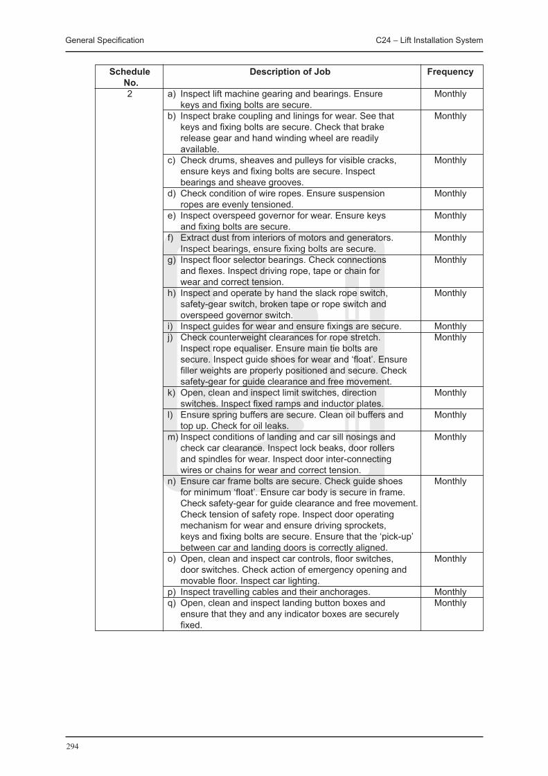
General Specification C24 – Lift Installation System
294
Schedule Description of job Frequency No. 2 a) Inspect lift machine gearing and bearings. Ensure Monthly keys and fixing bolts are secure. b) Inspect brake coupling and linings for wear. See that Monthly keys and fixing bolts are secure. Check that brake release gear and hand winding wheel are readily available. c) Check drums, sheaves and pulleys for visible cracks, Monthly ensure keys and fixing bolts are secure. Inspect bearings and sheave grooves. d) Check condition of wire ropes. Ensure suspension Monthly ropes are evenly tensioned. e) Inspect overspeed governor for wear. Ensure keys Monthly and fixing bolts are secure. f) Extract dust from interiors of motors and generators. Monthly Inspect bearings, ensure fixing bolts are secure. g) Inspect floor selector bearings. Check connections Monthly and flexes. Inspect driving rope, tape or chain for wear and correct tension. h) Inspect and operate by hand the slack rope switch, Monthly safety-gear switch, broken tape or rope switch and overspeed governor switch. i) Inspect guides for wear and ensure fixings are secure. Monthly j) Check counterweight clearances for rope stretch. Monthly Inspect rope equaliser. Ensure main tie bolts are secure. Inspect guide shoes for wear and ‘float’. Ensure filler weights are properly positioned and secure. Check safety-gear for guide clearance and free movement. k) Open, clean and inspect limit switches, direction Monthly switches. Inspect fixed ramps and inductor plates. l) Ensure spring buffers are secure. Clean oil buffers and Monthly top up. Check for oil leaks. m) Inspect conditions of landing and car sill nosings and Monthly check car clearance. Inspect lock beaks, door rollers and spindles for wear. Inspect door inter-connecting wires or chains for wear and correct tension. n) Ensure car frame bolts are secure. Check guide shoes Monthly for minimum ‘float’. Ensure car body is secure in frame. Check safety-gear for guide clearance and free movement. Check tension of safety rope. Inspect door operating mechanism for wear and ensure driving sprockets, keys and fixing bolts are secure. Ensure that the ‘pick-up’ between car and landing doors is correctly aligned. o) Open, clean and inspect car controls, floor switches, Monthly door switches. Check action of emergency opening and movable floor. Inspect car lighting. p) Inspect travelling cables and their anchorages. Monthly q) Open, clean and inspect landing button boxes and Monthly ensure that they and any indicator boxes are securely fixed.
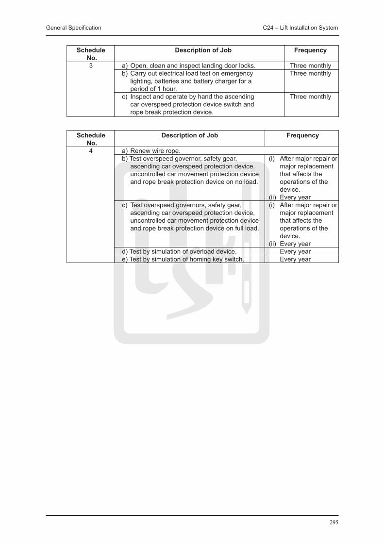
General Specification C24 – Lift Installation System
295
Schedule Description of job Frequency No. 3 a) Open, clean and inspect landing door locks. Three monthly b) Carry out electrical load test on emergency Three monthly lighting, batteries and battery charger for a period of 1 hour. c) Inspect and operate by hand the ascending Three monthly car overspeed protection device switch and rope break protection device.
Schedule Description of job Frequency No. 4 a) Renew wire rope. b) Test overspeed governor, safety gear, ascending car overspeed protection device, uncontrolled car movement protection device and rope break protection device on no load.
c) Test overspeed governors, safety gear, ascending car overspeed protection device, uncontrolled car movement protection device and rope break protection device on full load.
d) Test by simulation of overload device. e) Test by simulation of homing key switch.
(i) After major repair or major replacement that affects the operations of the device.
(ii) Every year(i) After major repair or
major replacement that affects the operations of the device.
(ii) Every year Every year Every year

296

297
C25 BroadcastReceptionInstallationSystem

General Specification C25 – Broadcast Reception Installation System
298
C25 BROADCAST RECEPTION INSTALLATION SYSTEM
C25.1 GENERAL REqUIREMENT
01 SITE SUPERVISION
The Contractor shall keep on Site a competent and technically qualified site supervisor to control, supervise and manage all his Works on Site. The supervisor shall be vested with suitable powers to receive instructions from the Contract Administrator.
The site supervisor shall be technically competent and have adequate site experience for the Works. The Contractor shall also refer to the Particular Specification for other specific requirements, if any, on site supervision.
Approval by the Contract Administrator shall be obtained prior to the posting of the supervisor on Site. The Contractor shall immediately replace the site supervisor whose experience, skill or competency is, in the opinion of the Contract Administrator, found to be inadequate for the particular work.
02 PROTECTION OF MATERIALS AND EqUIPMENT
Unless the responsibility is clearly defined in the Contract that the protection on Site for delivered equipment, materials and installation is solely by other contractors, the Contractor shall be responsible for the safe custody of all materials and equipment as stored or installed by him until finally inspected, tested and accepted. In addition, the Contractor shall protect all work against theft, fire, damage or inclement weather and carefully store all materials and equipment received on Site but not yet installed in a safe and secure place unless otherwise specified.
All cases of theft and fire must immediately be reported to the police, the Building Contractor, the Contract Administrator and the Contract Administrator’s representatives on Site with full details.
Where necessary the Contractor shall provide lockable steel container or other equally secure enclosures placed within a securely fenced-in compound provided by the Building Contractor on Site for the storage of materials and equipment.
The Contractor shall co-ordinate and arrange with the Building Contractor who shall provide clean, reasonably finished and lockable secure accommodation for the storage of sensitive and/or expensive items before installation.
If there is no Building Contractor, all the storage facilities and spaces shall be provided by the Contractor.
C25.2 MATERIALS AND EqUIPMENT SPECIFICATION
01 GENERAL
A Broadcast Reception system is designed with an aim to convey the best receivable signal at a particular site to individual users sharing the same system. The BR system performance shall comply with EN 50083-7:1996 and EN 50083-10:2002.
All apparatus, equipment, materials and wiring shall be suitable for use on 220 V ± 6 %, 50 Hz ± 2 Hz, single phase a.c. system at the following Services Conditions:
(i) Climate: Hong Kong (tropical); (ii) Ambient temperature: Peak -5°C to +40°C (continuously 4 hours) Average 0°C to +35°C (over 24 hours); (iii) Altitude: up to 2000 m above sea level; and (iv) Relative humidity: 98% maximum

General Specification C25 – Broadcast Reception Installation System
299
It should be noted that the supply voltage may be interrupted such that its frequency or voltage value may fluctuate outside the above acceptable range. It is advisable that the equipment should be able to ride through or function properly due to any unavoidable disturbance illustrated in the European Standard EN 50160:1999 and if not, the Contractor should state the performance of the equipment being complied with the specification requirements.
The Contractor should also make reference to the international practices of voltage dip ride-through capability, such as Semiconductor Equipment and Materials International (SEMI) F47 and IEC 61000-4-11:2004 & IEC 61000-4-34:2005.
C25.2.1 TERRESTRIAL MASTER ANTENNA TELEVISION SYSTEM
01 TERRESTRIAL AERIALS
The terrestrial aerials shall be suitable for both analogue and digital terrestrial television and shall comply with the following:
(i) TV aerial should have a gain of at least 13 dB and a front to back ratio of at least 28 dB. The aerial shall be of the type to minimize ghost image;
(ii) FM aerial should have a gain of at least 6 dB; (iii) The impedance of the aerial should be 75 ohm unbalanced; (iv) The aerial system should be provided with a durable protective coating; (v) The aerial mast should be made of stainless steel; and (vi) The aerial should be capable of receiving analogue and digital signals.
02 PREAMPLIFIERS AND FILTERS
The performance of the preamplifiers, TV bandpass preamplifiers, FM bandpass preamplifiers, TV bandpass filters and FM bandpass filters shall be suitable for both analogue and digital terrestrial television and shall comply with the following:
Preamplifiers
Television Standard PAL I System Frequency FM : 88 to 108 MHz TV : 54 to 862 MHz Gain ≧ 20 dB Input Split input configuration Output Level ≧ 90 dBμV Noise Figure < 5.5 dB Impedance (Input & Output) 75 ohms Housing Weatherproof housing suitable for outdoor
mounting
TV Bandpass Preamplifiers
Frequency Range Within CH 21 – CH 60 Passband Select the frequency range to suit the analogue
receptions & digital receptions required for any one free TV programme channel group as required by the location of reception in accordance with the frequency plans allocated for TV and FM receptions by OFTA
Gain within passband ≧ 20 dB Input Split input configuration Output Level ≧ 90 dBμV Noise figure < 5.5 dB Impedance (Input & Output) 75 ohm Housing Weatherproof housing suitable for outdoor
mounting
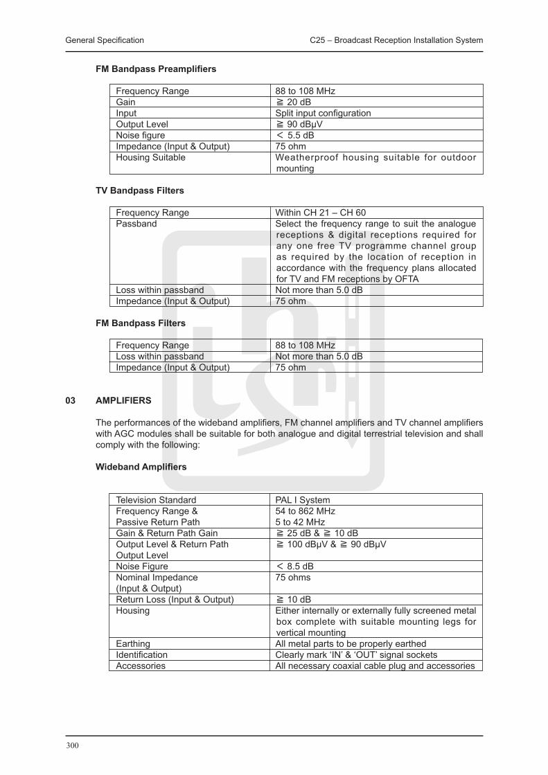
General Specification C25 – Broadcast Reception Installation System
300
FM Bandpass Preamplifiers
Frequency Range 88 to 108 MHz Gain ≧ 20 dB Input Split input configuration Output Level ≧ 90 dBμV Noise figure < 5.5 dB Impedance (Input & Output) 75 ohm Housing Suitable Weatherproof housing suitable for outdoor
mounting
TV Bandpass Filters
Frequency Range Within CH 21 – CH 60 Passband Select the frequency range to suit the analogue
receptions & digital receptions required for any one free TV programme channel group as required by the location of reception in accordance with the frequency plans allocated for TV and FM receptions by OFTA
Loss within passband Not more than 5.0 dB Impedance (Input & Output) 75 ohm
FM Bandpass Filters
Frequency Range 88 to 108 MHz Loss within passband Not more than 5.0 dB Impedance (Input & Output) 75 ohm
03 AMPLIFIERS
The performances of the wideband amplifiers, FM channel amplifiers and TV channel amplifiers with AGC modules shall be suitable for both analogue and digital terrestrial television and shall comply with the following:
Wideband Amplifiers
Television Standard PAL I System Frequency Range & 54 to 862 MHz Passive Return Path 5 to 42 MHz Gain & Return Path Gain ≧ 25 dB & ≧ 10 dB Output Level & Return Path ≧ 100 dBμV & ≧ 90 dBμV Output Level Noise Figure < 8.5 dB Nominal Impedance 75 ohms (Input & Output) Return Loss (Input & Output) ≧ 10 dB Housing Either internally or externally fully screened metal
box complete with suitable mounting legs for vertical mounting
Earthing All metal parts to be properly earthed Identification Clearly mark ‘IN’ & ‘OUT’ signal sockets Accessories All necessary coaxial cable plug and accessories
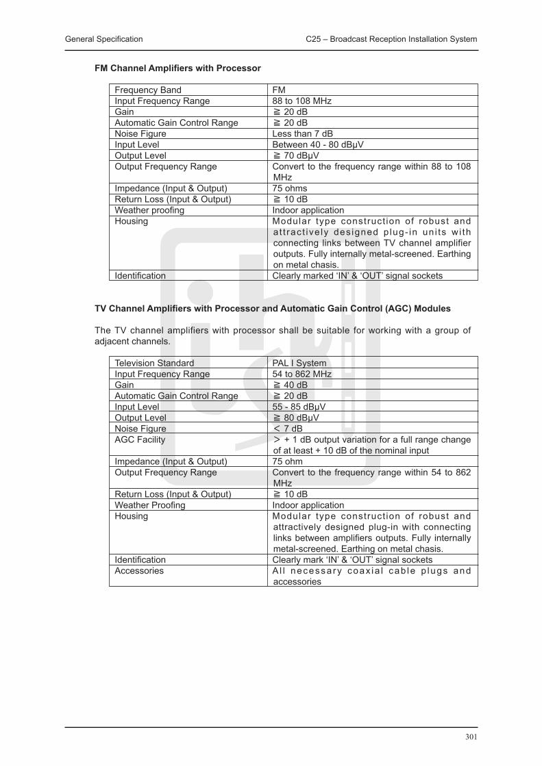
General Specification C25 – Broadcast Reception Installation System
301
FM Channel Amplifiers with Processor
Frequency Band FM Input Frequency Range 88 to 108 MHz Gain ≧ 20 dB Automatic Gain Control Range ≧ 20 dB Noise Figure Less than 7 dB Input Level Between 40 - 80 dBμV Output Level ≧ 70 dBμV Output Frequency Range Convert to the frequency range within 88 to 108
MHz Impedance (Input & Output) 75 ohms Return Loss (Input & Output) ≧ 10 dB Weather proofing Indoor application Housing Modular type construct ion of robust and
a t t rac t ive ly des igned p lug- in un i ts w i th connecting links between TV channel amplifier outputs. Fully internally metal-screened. Earthing on metal chasis.
Identification Clearly marked ‘IN’ & ‘OUT’ signal sockets
TV Channel Amplifiers with Processor and Automatic Gain Control (AGC) Modules
The TV channel amplifiers with processor shall be suitable for working with a group of adjacent channels.
Television Standard PAL I System Input Frequency Range 54 to 862 MHz Gain ≧ 40 dB Automatic Gain Control Range ≧ 20 dB Input Level 55 - 85 dBμV Output Level ≧ 80 dBμV Noise Figure < 7 dB AGC Facility > + 1 dB output variation for a full range change
of at least + 10 dB of the nominal input Impedance (Input & Output) 75 ohm Output Frequency Range Convert to the frequency range within 54 to 862
MHz Return Loss (Input & Output) ≧ 10 dB Weather Proofing Indoor application Housing Modular type construct ion of robust and
attractively designed plug-in with connecting links between amplifiers outputs. Fully internally metal-screened. Earthing on metal chasis.
Identification Clearly mark ‘IN’ & ‘OUT’ signal sockets Accessories A l l necessa ry coax ia l cab le p lugs and
accessories

General Specification C25 – Broadcast Reception Installation System
302
04 FREqUENCY CONVERTERS
The frequency converters shall comply with the following:
Frequency Range 87 to 108 MHz Gain ≧ 20 dB Automatic Gain Control Range ≧ 20 dB Input Level 55 - 85 dBμV Output Level ≧ 60 dBμV Output RF Bandwidth < 8MHz AGC Facility > + 1 dB output variation for a full range change
of at least + 10 dB of the nominal input Impedance (Input & Output) 75 ohm Weather Proofing Indoor application Housing Modular type construct ion of robust and
attractively designed plug-in with connecting links between amplifiers outputs. Fully internally metal-screened. Earthing on metal chasis.
Identification Clearly mark ‘IN’ & ‘OUT’ signal sockets Accessories A l l necessa ry coax ia l cab le p lugs and
accessories
05 UHF MODULATORS The UHF modulators shall comply with the following:
Video Input Level 1 + 0.3 Vpp Video Input Impedance 75 ohm Video Bandwidth 0.020 – 5.0 MHz Output Frequency Range 54 to 862 MHz f ixed channel or channel
selectable Output Impedance 75 ohm Output RF Bandwidth < 8 MHz Output Level (without integrated channel amp) > 80 dBμV (with integrated channel amp) > 110 dBμV
06 SPLITTERS/TEE-UNITS
All splitters and tee units shall have a wide bandwidth to allow for cascaded mode of operation, shall have return path and shall comply with the following:
Splitters
Frequency Range 5 to 862 MHz Distribution Loss ≦ 8 dB Mutual Attenuation between Outputs Not less than 13 dB for splitters at all in-band
frequencies Impedance 75 ohm Return Loss (Input & Output) ≧ 14 dB
Tee Units Frequency Range 5 to 862 MHz Thru Loss ≦ 6 dB Side Loss ≦ 16.5 dB Mutual Attenuation between Outputs Not less than 28 dB for tee units at all in-band
frequencies Impedance 75 ohm Return Loss (Input & Output) ≧ 18 dB

General Specification C25 – Broadcast Reception Installation System
303
07 COAXIAL CABLES
All coaxial cables used shall be of 75 ohm type copper cables designed for transmitting 5 to 2150 MHz signals and shall have thermosetting insulated, with low emission of smoke and corrosive gases when affected by fire.
The fire performance of the insulated material with low emission of smoke and corrosive gases when affected by fire shall comply with the following requirements:
(i) Flame propagation : IEC 60332-1-1:2004; (ii) Smoke emission : IEC 61034-2:2005; and (iii) Acid gas emission : IEC 60754-1:1994
The coaxial cables for feeder shall conform to cable designation 8 or above of IEC 60096-3:1982 and the coaxial cables for trunk feeder shall conform to cable designation 6 or above of IEC 60096-3:1982.
Underground coaxial cables shall be with polyethylene outer sheath, copper foil outer conductor, and PVC insulation. The cable shall conform to cable designation 6 or above of IEC 60096-3:1982.
All coaxial cables shall have distinctive labels/brand name along its length.
08 FM/TV/DATA TRIPLEX OUTLETS
Outlets shall be triplex socket type for data (5 to 862 MHz) signal and for FM/TV (54 to 862 MHz) signals complete with frequency dividing network and the respective socket shall be identified with labels embossed on the front plate. The outlet shall be suitable for analogue and digital signals.
The triplex outlets shall be suitable for flush mounting on 47 mm deep IEC 60670-1:2002 & relevant current parts box.
Unless otherwise specified, the triplex outlets shall be white or ivory in colour.
The FM/TV/Data triplex outlet shall have a return path and shall comply with the following:
Frequency Range & 54 to 862 MHz Return Path Frequency 5 to 42 MHz Features Triplex outlets configuration one for data and two
for FM/TV, flush mounting type complete with cover, connected from tap output of tee unit.
Distribution Loss FM (88 to108 MHz) < 10 dB TV & Data (5 to 862 MHz) < 9 dB Mutual Isolation Between FM, TV & Data not less than 40 dB from
88 to 862 MHz Impedance 75 ohm

General Specification C25 – Broadcast Reception Installation System
304
09 FIBER OPTICAL TRANSMITTER
The fiber optical transmitter shall be of modular design and shall comply with the following:
Frequency 54 to 862 MHz Input Impedance 75 ohm Optical Wavelength 1310 nm ± 10 nm Optical Output Power ≧ 6 dBm Optical Return Loss ≧ 55 dB RF Input Level per Channel ≧ 60 dBμV Number of TV channels 42 Light Source – LED Laser < 2 km Diode < 40 km
The fiber optical return path transmitter shall be of modular design and shall comply with the following:
Frequency & 54 to 862 MHz Return Path Frequency 5 to 42 MHz or as specified Optical Wavelength 1310 nm ± 10 nm Optical Return Loss ≧ 55 dB RF Output Level per Channel > 80 dBμV Return Path Loss > 14 dB Light Source – LED Laser < 2 km Diode < 40 km
10 FIBER OPTICAL SPLITTER
The fiber optical splitter shall be of modular design and shall comply with the following:
Optical Wavelength 1310 nm ± 10 nm Optical Return Loss ≧ 55 dB
11 FIBER OPTICAL CABLE
The fiber optical cable shall be flame retardant type. The cable shall be single mode (1310 nm) and shall be suitable for 5 to 2050 MHz applications. The maximum attenuation shall be 0.45 dB/km.
25.2.2 SATELLITE MASTER ANTENNA TELEVISION SYSTEM
01 SYSTEM REqUIREMENTS
The system shall enable simultaneous viewing different TV programs from the Terrestrial Master Antenna Television System as well as from satellites. Signals from the Satellite Master Antenna Television System shall be fed to the satellite receivers installed in the Headend Equipment Room, via necessary signal splitting equipment, satellite amplifiers and cabling. The video and audio signals from the satellite receivers shall be modulated to SMATV channels and shall be combined to the Broadcast Reception installation headend equipment installed in the Headend Equipment Room for distribution to FM/TV/Data triplex outlets.
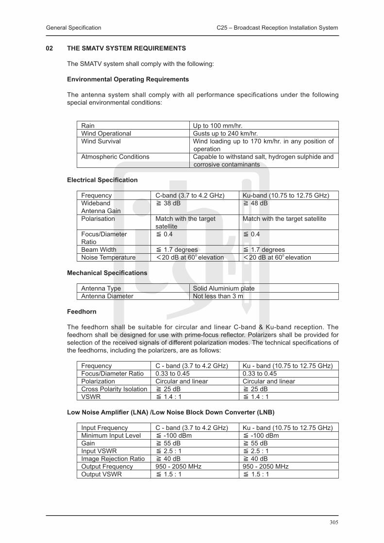
General Specification C25 – Broadcast Reception Installation System
305
02 THE SMATV SYSTEM REqUIREMENTS
The SMATV system shall comply with the following:
Environmental Operating Requirements
The antenna system shall comply with all performance specifications under the following special environmental conditions:
Rain Up to 100 mm/hr. Wind Operational Gusts up to 240 km/hr. Wind Survival Wind loading up to 170 km/hr. in any position of
operation Atmospheric Conditions Capable to withstand salt, hydrogen sulphide and
corrosive contaminants
Electrical Specification
Frequency C-band (3.7 to 4.2 GHz) Ku-band (10.75 to 12.75 GHz) Wideband ≧ 38 dB ≧ 48 dB Antenna Gain Polarisation Match with the target Match with the target satellite satellite Focus/Diameter ≦ 0.4 ≦ 0.4 Ratio Beam Width ≦ 1.7 degrees ≦ 1.7 degrees Noise Temperature <20 dB at 60o elevation <20 dB at 60o elevation
Mechanical Specifications
Antenna Type Solid Aluminium plate Antenna Diameter Not less than 3 m
Feedhorn
The feedhorn shall be suitable for circular and linear C-band & Ku-band reception. The feedhorn shall be designed for use with prime-focus reflector. Polarizers shall be provided for selection of the received signals of different polarization modes. The technical specifications of the feedhorns, including the polarizers, are as follows:
Frequency C - band (3.7 to 4.2 GHz) Ku - band (10.75 to 12.75 GHz) Focus/Diameter Ratio 0.33 to 0.45 0.33 to 0.45 Polarization Circular and linear Circular and linear Cross Polarity Isolation ≧ 25 dB ≧ 25 dB VSWR ≦ 1.4 : 1 ≦ 1.4 : 1
Low Noise Amplifier (LNA) /Low Noise Block Down Converter (LNB)
Input Frequency C - band (3.7 to 4.2 GHz) Ku - band (10.75 to 12.75 GHz) Minimum Input Level ≦ -100 dBm ≦ -100 dBm Gain ≧ 55 dB ≧ 55 dB Input VSWR ≦ 2.5 : 1 ≦ 2.5 : 1 Image Rejection Ratio ≧ 40 dB ≧ 40 dB Output Frequency 950 - 2050 MHz 950 - 2050 MHz Output VSWR ≦ 1.5 : 1 ≦ 1.5 : 1
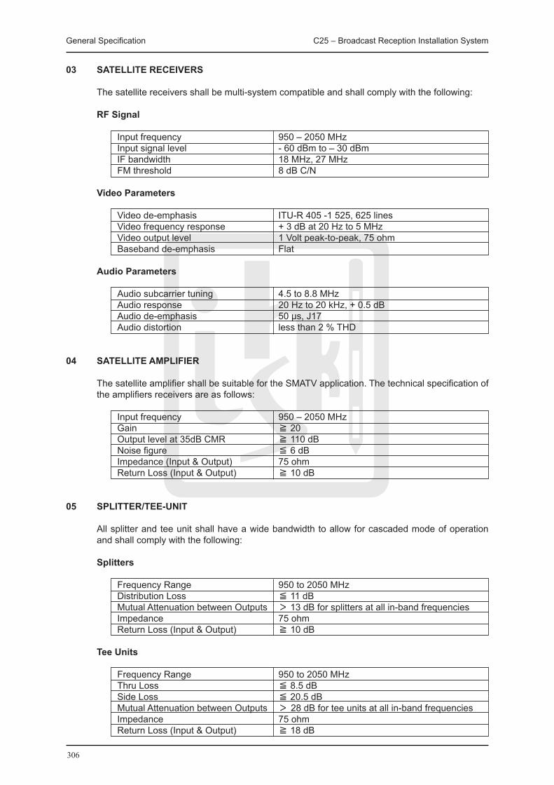
General Specification C25 – Broadcast Reception Installation System
306
03 SATELLITE RECEIVERS
The satellite receivers shall be multi-system compatible and shall comply with the following:
RF Signal
Input frequency 950 – 2050 MHz Input signal level - 60 dBm to – 30 dBm IF bandwidth 18 MHz, 27 MHz FM threshold 8 dB C/N
Video Parameters
Video de-emphasis ITU-R 405 -1 525, 625 lines Video frequency response + 3 dB at 20 Hz to 5 MHz Video output level 1 Volt peak-to-peak, 75 ohm Baseband de-emphasis Flat
Audio Parameters Audio subcarrier tuning 4.5 to 8.8 MHz Audio response 20 Hz to 20 kHz, + 0.5 dB Audio de-emphasis 50 μs, J17 Audio distortion less than 2 % THD
04 SATELLITE AMPLIFIER
The satellite amplifier shall be suitable for the SMATV application. The technical specification of the amplifiers receivers are as follows:
Input frequency 950 – 2050 MHz Gain ≧ 20 Output level at 35dB CMR ≧ 110 dB Noise figure ≦ 6 dB Impedance (Input & Output) 75 ohm Return Loss (Input & Output) ≧ 10 dB
05 SPLITTER/TEE-UNIT
All splitter and tee unit shall have a wide bandwidth to allow for cascaded mode of operation and shall comply with the following:
Splitters
Frequency Range 950 to 2050 MHz Distribution Loss ≦ 11 dB Mutual Attenuation between Outputs > 13 dB for splitters at all in-band frequencies Impedance 75 ohm Return Loss (Input & Output) ≧ 10 dB
Tee Units
Frequency Range 950 to 2050 MHz Thru Loss ≦ 8.5 dB Side Loss ≦ 20.5 dB Mutual Attenuation between Outputs > 28 dB for tee units at all in-band frequencies Impedance 75 ohm Return Loss (Input & Output) ≧ 18 dB

General Specification C25 – Broadcast Reception Installation System
307
C25.2.3 ANCILLARY SYSTEM
01 CABLE TRUNKING
Cable trunking shall be in accordance with the “General Specification for Electrical Installation in Government Buildings, Hong Kong, issued by Architectural Services Department, the Government of the HKSAR”.
02 CONDUIT AND ACCESSORIES
Conduit & accessories shall be in accordance with the “General Specification for Electrical Installation in Government Buildings, Hong Kong, issued by Architectural Services Department, the Government of the HKSAR”.
03 POWER CABLE
Power cable shall be in accordance with the “General Specification for Electrical Installation in Government Buildings, Hong Kong, issued by Architectural Services Department, the Government of the HKSAR”.
C25.3 INSPECTION, TESTING & COMMISSIONING
01 VISUAL INSPECTION OF INSTALLATION
A visual inspection shall be carried out before testing of the installation in order to verify the following:
(i) The installation has been carried out in compliance with the specified requirements; (ii) The correctness of the designation of the installation; and (iii) There is no visual damage to the installation.
02 GENERAL
Upon completion of the installed works, the Contractor shall give due advanced notice and provide details of date, time and list of testing and commissioning works to the Contract Administrator or his representative for approval.
The Contractor shall submit the appropriate schedule and phasing of the testing and commissioning works as agreed by the Contract Administrator or his representative.
Where testing and commissioning works are required to be witnessed by the Contract Administrator, his representative and site supervisory staff, the Contractor shall carry out the proper testing and commissioning works before inviting them to witness the works.
03 TESTING AND COMMISSIONING PROCEDURES
The Contractor shall carry out the testing and commissioning works in accordance with the Testing and Commissioning Procedure for Broadcast Reception Installation in Government Building.
The Contractor shall submit proposed testing and commissioning programmes, testing and commissioning methods, procedures and formats of test records to the Contract Administrator for approval. The submission shall be submitted together with a list of major equipment with their crucial information such as brand names, model numbers, types, capacities and locations.
The Contractor shall check and ensure that all related building items such as false ceiling, partitions, windows, louvers, etc. that will affect proper operation of the system have been provided and ready for carrying out of the commissioning before starting commissioning works.
General Specification C25 – Broadcast Reception Installation System
308
04 ROUTINE HALF-YEARLY INSPECTION, TESTING AND MAINTENANCE
The Contractor shall visit the installation at least once every 6 months to carry out tests, repairs and adjustment. All environmentally sensitive devices shall be inspected, cleaned, adjusted and calibrated. A test sequence shall be carried out in accordance with the manufacturer’s instructions.
C25.4 OPERATION AND MAINTENANCE (O&M) MANUAL AND USER MANUAL
01 GENERAL
The Contractor shall provide two types of manuals to the Contract Administrator with all changes made to the installation during the course of the Contract suitably incorporated.
The O&M Manual is for use by the maintenance agent of the completed installation. It shall contain detailed technical information covering both operation and maintenance aspects of the installation.
The User Manual seeks to give users of the completed installation an overview of the essential information of the installation. The contents of the manual shall be concise and succinct for ease of comprehension by people with a non-technical background.
02 PRESENTATION
All manuals shall be written in English, unless otherwise specified. The text of descriptive parts shall be kept concise while at the same time ensure completeness. Diagrammatic materials shall also be supported by comprehensive descriptions. The Contract Administrator’s approval shall be obtained on this at the draft manual.
03 STRUCTURE AND CONTENTS OF O&M MANUAL
The detailed requirements, structure and contents of the O&M Manual shall be as specified elsewhere in the Contract and shall include the following information under separate sections where appropriate:
(i) Project Information include: Project title, site address, contract no., contract title, main contractor/lift contractor name,
address, contact persons and their telephone/fax nos., contract commencement date, substantial completion date and end date of maintenance period.
(ii) System Description (a) Type(s) of system(s) and equipment installed; (b) Design criteria, design data and parameters; (c) Locations of the system and major equipment, and what they serve; (d) Description of operation and functions of the system and equipment; and (e) General operating conditions, expected performance and energy and resources
consumption where applicable. (iii) List of Installed Equipment (a) Schedule of all items of equipment and plant stating the location, name, model no.,
manufacturer’s serial or reference no., manufacturer’s design duties and data. (iv) Spare Parts and Special Tools Lists (a) List of Spare Parts supplied by the Contractors including item descriptions, supplied
quantities, model nos., manufacturer’s serial or reference nos. and storage locations. (b) Recommended Spare Parts List and Special Tools List including Manufacturers’/
suppliers’ recommendations for spare parts and special tools with item description, unit rate, recommended stock quantities as well as the agents for the spare parts and special tools.
(v) Manufacturers’ Certificates/Guarantees (a) Manufacturers’ certificates such as factory test certificates, laboratory test reports and
guarantees and any others where required for the equipment and plants, etc. (b) Originals of Statutory Inspection Certificate for various installations. Testing records & commissioning data (other than the types prescribed above), which are

General Specification C25 – Broadcast Reception Installation System
309
required under the Contract such as the T&C procedures, etc to verify the compliance of the BS/E&M system’s/equipment’s performance with the contract requirements, are checked and endorsed separately by the Contract Administrator and do not form part of the O&M manuals.
(vi) Safety Precautions for Operation and Maintenance State, where applicable, hazard warnings and safety precautions of which the operation
and maintenance staff need to be aware: (a) mandatory requirements relating to safety; (b) known hazards against which protection measures shall be taken; and (c) known features or operational characteristics of the installed equipment or systems
which may cause hazard and the related safety precautions. (vii) Operation Instructions Instructions for the safe and efficient operation, under both normal and emergency
conditions, of the installed system which shall comprise: (a) an outline of the operating mode; (b) control logic and data (sequence, effect, limits of capability, modes and set points); (c) procedures and sequences for start-up and shut-down; (d) interlocks between equipment/system; (e) calling on of stand-by equipment; (f) precautions necessary to overcome known hazards; (g) means by which any potentially hazardous equipment can be made safe; (h) estimation of energy consumption and energy costs; (i) forms for recording plant running hours, energy consumption and energy costs; and (j) operating data such as running current, operating pressure, operating flow rates, etc. (viii) Maintenance instructions Manufacturers’ and the Contractor ’s recommendations and instructions for the
maintenance of the installed equipment. Clear distinction should be made between planned tasks (preventive maintenance) and fault-repair tasks (corrective maintenance). Instructions shall be given on each of the following, as appropriate:
(a) nature of deterioration, and the defects to be looked for; (b) isolation and return to service of plant and equipment; (c) dismantling and reassembly; (d) replacement of components and assemblies; (e) dealing with hazards which may arise during maintenance; (f) adjustments, calibration and testing; and (g) special tools, test equipment and ancillary services. (ix) Maintenance schedules Proposed maintenance schedules for all the preventive maintenance tasks identified
above. The schedules shall be based on both manufacturers’ recommendations and other authoritative sources (e.g. statutory or mandatory requirements) and should include:
(a) routine servicing; (b) inspections; (c) tests and examinations; (d) adjustments; (e) calibration; and (f) overhaul. The frequency of each task may be expressed as specific time intervals, running hours
or number of completed operations as appropriate. Collectively, the schedules will form a complete maintenance cycle, repeated throughout the whole working life of the installation.
(x) Drawing Lists (a) A complete list of as-built drawings identified with drawing number/reference; (b) A complete list of manufacturers’ shop drawings with drawing number/reference,
where applicable; and (c) A brief description of CD-ROM for these drawings. (xi) Technical Literatures A complete set of manufacturers’ literatures for all the plant and equipment installed in the
system. The contents of these literatures shall cover the following areas where applicable: (a) description of equipment with model numbers highlighted; (b) performance - behavioral characteristics of the equipment;

General Specification C25 – Broadcast Reception Installation System
310
(c) applications - suitability for use; (d) factory/laboratory test reports, detailed drawings, circuit diagrams; (e) methods of operation and control; (f) operation instructions; (g) cleaning and maintenance requirements; (h) plants, materials and space required for maintenance; (i) protective measures and safety precautions for operation and maintenance; and (j) part lists. (xii) Contact addresses and telephone numbers of suppliers of major equipment.
04 STRUCTURE AND CONTENTS OF USER MANUAL
The detailed requirements, structure and contents of the User Manual shall include, where applicable, the following information:
(i) Project Information This shall include project title, site address, contract no., contract title, contract
commencement date, substantial completion date and end date of Maintenance Period. (ii) System Description (a) Type(s) of system(s) and equipment installed, and their purposes; (b) Locations of major plant rooms and riser ducts; (c) Brief description of the operation and functions of the systems and equipment; and (d) Listing of set points which can be adjusted by the user to suit their operation needs. (iii) Schedule of Major Plant Rooms and Installed Equipment (a) Schedule of major plant rooms and riser ducts including their locations; and (b) Schedule of major equipment and plants including their locations and serving areas. (iv) Safety Precautions for Operation Any safety precautions and warnings signals that the users shall be aware of in the daily
operation of the various systems and equipment in the installation including: (a) mandatory requirements relating to safety; (b) features or operational characteristics of the installed systems or equipment which
may cause hazard and the related safety precautions; (c) protective measures and safety precautions for operation; and (d) list of warning signals and the related meanings that the user shall be aware of and
the actions to be taken. (v) Operation Instructions Instructions for the safe and efficient operation, under both normal and emergency
conditions, of the installed system which shall comprise: (a) an outline of the operating mode; (b) step by step operation instructions for systems and equipment that are to be operated
by the user, including at least procedures for start-up and shut-down; (c) means by which any potentially hazardous situation can be made safe; and (d) cleaning and basic maintenance procedures. (vi) List of Statutory Periodic Inspections and Tests A schedule of periodic inspections and tests that owner and/or user of the installation have
to arrange to achieve compliance with the requirements stipulated in the relevant Laws of Hong Kong. The frequency of such inspections and tests shall be expressed in specific time intervals.
(vii) Drawings A set of selected as-built drawings which shall be able to illustrate to the user the general
layout of the completed installation. (viii) Photographs A set of photographs with suitable captions to illustrate to the user the appearance and
locations of devices which require their setting and operation.

311
C26 SecuritySystem

General Specification C26 – Security System
312
C26 SECURITY SYSTEM
C26.1 GENERAL REqUIREMENT
01 SITE SUPERVISION
The Contractor shall keep on Site a competent and technically qualified site supervisor to control, supervise and manage all his Works on Site. The supervisor shall be vested with suitable powers to receive instructions from the Contract Administrator.
The site supervisor shall be technically competent and have adequate site experience for the Works. The Contractor shall also refer to the Particular Specification for other specific requirements, if any, on site supervision.
Approval by the Contract Administrator shall be obtained prior to the posting of the supervisor on Site. The Contractor shall immediately replace the site supervisor whose experience, skill or competency is, in the opinion of the Contract Administrator, found to be inadequate for the particular work.
02 PROTECTION OF MATERIALS AND EqUIPMENT
Unless the responsibility is clearly defined in the Contract that the protection on Site for delivered equipment, materials and installation is solely by other contractors, the Contractor shall be responsible for the safe custody of all materials and equipment as stored or installed by him until finally inspected, tested and accepted. In addition, the Contractor shall protect all work against theft, fire, damage or inclement weather and carefully store all materials and equipment received on Site but not yet installed in a safe and secure place unless otherwise specified.
All cases of theft and fire must immediately be reported to the police, the Building Contractor, the Contract Administrator’s representatives on Site with full details.
Where necessary the Contractor shall provide lockable steel container or other equally secure enclosures placed within a securely fenced-in compound provided by the Building Contractor on Site for the storage of materials and equipment.
The Contractor shall co-ordinate and arrange with the Building Contractor who shall provide clean, reasonably finished and lockable secure accommodation for the storage of sensitive and/or expensive items before installation.
If there is no Building Contractor, all the storage facilities and spaces shall be provided by the Contractor.
C26.2 MATERIALS AND EqUIPMENT SPECIFICATION
01 SECURITY SYSTEM
The Contractor shall supply and install a security system consisting of alarm bells, key switches, magnetic door contacts, motion detectors, alarm indicator panels and system control panel as shown on the Drawings.
The security system shall operate in the following mode:-
The security system shall operate on a 12V or 24V D.C. supply and shall be backed up by emergency power supply. To meet this requirement, the security system shall be provided with secondary battery supply, uninterrupted power supply, or an approved source of backup power supply accepted by the Contract Administrator even when they are connected to the emergency generator.
The security system shall be of “fail-safe” design, e.g. alarm shall raise upon the power supply
General Specification C26 – Security System
313
fails.
All electric and electromagnetic door locking devices shall release upon receiving a fire signal from the Automatic Fire Alarm system to maintain means of escape in case of fire.
Upon the key switch is switched to “ON” position at the main security control panel, the system is enabled.
If any detection device in the protected areas of the security system as indicated on the Drawings is activated while its key switch outside the corresponding location is at “ON” position, alarm shall be activated.
The magnetic door contact shall raise an alarm, whenever the door is opened in an “Enable” mode. The motion detector shall raise an alarm whenever it detects an intruder in the “Enable” mode.
The alarm shall cause the followings to operate:-
(i) The corresponding alarm bell(s) mounted outside the rooms/locations as stated in Clause O.2.4 above to operate.
(ii) The buzzer and the corresponding alarm indicator(s) on the security system main control panel installed inside the General Office.
(iii) The buzzer and the corresponding alarm indicator(s) on the security system repeated panel installed inside the Staff Quarters.
When the key switch installed at the position outside the rooms/locations as stated in Clause
O.2.4 and as shown on the Drawings where the alarm signal is activated is switched to the “OFF” position, the alarm shall be reset.
The key switch shall be made of stainless steel plate. It shall have a “ON” and a “OFF” position with LED indicators. The key switch shall have an engraved label bearing the word “ON” and “OFF” in both Chinese and English characters. 3 no. keys i.e. one for School Principal, two keys for the responsible persons to enable/disable the system shall be provided.
The magnetic door contact shall be of heavy duty and shall be cylindrical recessed inserted into the door/door frame. The magnetic switch shall be suitable for use with 25mm gap.
The motion detector shall be installed as shown on the Drawings for detection of any intruder entering through the door or through the louvre.
The motion detectors shall be of passive infrared microwave verified type which shall detect movement by passive infrared technology and also by microwave technology. An alarm signal shall be sent to the control panel if both the passive infrared and microwave components of the sensor have been activated within a specified time. For the passive infrared component, the detectors shall keep constant monitoring of the ‘thermal pattern’ of the protected area. Any rapid alteration of the infra red energy within the protected area shall trigger the alarm of the passive infrared component. However, a slow and gradual temperature change shall not cause an alarm. The infrared beam shall not penetrate glass, thin wall or plastics. The microwave component shall keep constant monitoring of the protected area by detecting the Doppler shift of microwave emitted from the detector. The detector shall generate ‘K’ band microwave frequency of around 24 GHz and emit it as unmodulated electromagnetic field to the protected area or volume. The range of detection shall be adjustable up to 18m, the pattern of detection shall be 90o adjustable ±45o horizontally and –7o vertically. The velocity of the target to be detected shall be 150-3000 mm per second. The sensitivity of the passive infrared components shall be 2oC at a target velocity of 600 mm per second. The electronic circuit of the detectors shall be protected against high level radio frequency interference, and shall be insensitive to thermal and optical source of interference. A LED indicating trouble shall be lit when:
(i) excessive temperature, (ii) fall in input voltage below the correct performance of the detector is assured, (iii) interruption of microwave operation (e.g. due to masking or failure of the microwave
General Specification C26 – Security System
314
component. A LED shall be provided to indicate ON/OFF status of the “walk test” mode. The detector shall be one piece and shall be housed in a tamper-proof housing with tampering switch, alarm signal shall be sent to the control panel when the housing is tampered.
The alarm bell shall have a different sound from the other bell systems employed in the school. It shall be operated on 12V or 24V DC. The loudness of the bell shall not be less than 85 decibels at a distance of 3 m in front of the bell. Tamper switch shall be provided in the alarm units.
The security system main control panel installed inside the General Office on G/F and shall have, but not limited to the followings:-
(i) Alarm indications for the areas specified as shown on the drawing. Indications showing power on and off, security system on and off, circuit healthy status
and battery low. (ii) Buzzer muting switch. Alarm/system reset key switch. (iii) Buzzer and lamp test button. (iv) 220V A.C./12V or 24V D.C. step down transformer. (v) Battery charger and batteries shall be supplied, installed and tested in accordance of the
specification laid down in the Schedule No. 9 of this Particular Specification. (vi) The control panel shall be engraved in both Chinese and English characters. The layout
shall be submitted for approval prior to installation.
Vandal-proof micro-switches shall be provided for the key switches, alarm bells, control panel and repeater panels to prevent vandalism.
The Contractor shall provide training to representatives of the end-user. The course shall include introduction to the Burglar Alarm and Security system installed and on how to effectively operate the system.
02 LOCAL P.A. SYSTEM
Cable containment facilities for local P.A. system comprises of junction box for microphone jack, amplifier and speakers shall be provided to the rooms as shown on drawings.
03 BUILDER’S WORK
The Contractor is responsible for the builder’s work as detailed on the Drawings under building work. The Contractor shall ensure that the arrangement, routing, number and sizes of all wall openings and concrete plinths for the installation are suitable. The Contractor shall provide detailed information for such builder’s work requirement to the Building Contractor in sufficient time for co-ordination and for obtaining Contract Administrator’s approval.
The Contractor shall submit all detail drawings & fixing details to the Contract Administrator for approval prior to fabrication & installation.
The Contractor shall mark on site details of works to be executed by the Building Contractor in accordance with the approved drawings.
04 IDENTIFICATION OF SERVICES
Labels and notices shall be supplied and installed as according to E.G.S.
All equipment and electrical accessories installed shall be identified to give clear indication of the function and purpose of each item. Identification may be effected by suitable labels and/or markings.
Isolators, D.P. switches, spur boxes etc. shall be engraved, on the front plates, with the appropriate words to denote the appliance or equipment they are controlling. The wordings

General Specification C26 – Security System
315
shall be submitted to the Contract Administrator for approval.
Samples of labels and marking for identification purposes shall be submitted to Contract Administrator for approval.
C26.3 INSPECTION, TESTING & COMMISSIONING
01 VISUAL INSPECTION OF INSTALLATION
A visual inspection shall be carried out before testing of the installation in order to verify the following:
(i) The installation has been carried out in compliance with the specified requirements; (ii) The correctness of the designation of the installation; and (iii) There is no visual damage to the installation.
02 GENERAL
Upon completion of the installed works, the Contractor shall give due advanced notice and provide details of date, time and list of testing and commissioning works to the Contract Administrator or his representative for approval.
The Contractor shall submit the appropriate schedule and phasing of the testing and commissioning works as agreed by the Contract Administrator or his representative.
Where testing and commissioning works are required to be witnessed by the Contract Administrator or his representative and site supervisory staff, the Contractor shall carry out the proper testing and commissioning works before inviting them to witness the works.
03 TESTING AND COMMISSIONING PROCEDURES
The Contractor shall carry out the testing and commissioning works in accordance with the Testing and Commissioning Procedure for Broadcast Reception Installation in Government Building.
The Contractor shall submit proposed testing and commissioning programmes, testing and commissioning methods, procedures and formats of test records to the Contract Administrator for approval. The submission shall be submitted together with a list of major equipment with their crucial information such as brand names, model numbers, types, capacities and locations.
The Contractor shall check and ensure that all related building items such as false ceiling, partitions, windows, louvers, etc. that will affect proper operation of the system have been provided and ready for carrying out of the commissioning before starting commissioning works.
04 TESTING AND COMMISSIONING
The Electrical Installation shall be tested and commissioned fully in accordance with Part D of the “Electrical General Specification” and “Building Services Branch Testing and Commissioning Procedure No. 2 for Electrical Installation in Government Buildings, Hong Kong (2002 Edition)”. The Contractor shall follow the manufacturer’s recommendation of the testing and commissioning of any proprietary system and product included in the installation.
The Burglar Alarm and Security Installation shall be tested and commissioned fully in accordance with “Building Services Branch Testing and Commissioning Procedure No. 5 for Burglar Alarm and Security Installation in Government Buildings, Hong Kong (2000 Edition)”.
The Contractor shall allow for the attendance on testing and inspection of the Electrical Installation to be conducted by the local electricity supply company so as to ensure that permanent electricity supply will be energized in good time to the satisfaction of the Contract Administrator.
General Specification C26 – Security System
316
All submissions as required under these procedures are to be submitted to the Contract Administrator at least 28 days prior to the commencement of testing and commissioning work.
The Contractor shall provide all labour, instruments and materials necessary for the performance tests and make all necessary adjustments, including measurement of illumination level and checking of operation and submits test results.
05 ROUTINE HALF-YEARLY INSPECTION, TESTING AND MAINTENANCE
The Contractor shall visit the installation at least once every 6 months to carry out tests, repairs and adjustment. All environmentally sensitive devices shall be inspected, cleaned, adjusted and calibrated. A test sequence shall be carried out in accordance with the manufacturer’s instructions.
C26.4 OPERATION AND MAINTENANCE (O&M) MANUAL AND USER MANUAL
01 GENERAL
The Contractor shall provide two types of manuals to the Contract Administrator with all changes made to the installation during the course of the Contract suitably incorporated.
The O&M Manual is for use by the maintenance agent of the completed installation. It shall contain detailed technical information covering both operation and maintenance aspects of the installation.
The User Manual seeks to give users of the completed installation an overview of the essential information of the installation. The contents of the manual should be concise and succinct for ease of comprehension by people with a non-technical background.
02 PRESENTATION
All manuals shall be written in English, unless otherwise specified. The text of descriptive parts shall be kept concise while at the same time ensure completeness. Diagrammatic materials shall also be supported by comprehensive descriptions. The Contract Administrator’s approval shall be obtained on this at the draft manual.
03 STRUCTURE AND CONTENTS OF O&M MANUAL
The detailed requirements, structure and contents of the O&M Manual shall be as specified elsewhere in the Contract and shall include the following information under separate sections where appropriate:
(i) Project Information include: Project title, site address, contract no., contract title, main contractor/lift contractor name,
address, contact persons and their telephone/fax nos., contract commencement date, substantial completion date and end date of maintenance period.
(ii) System Description (a) Type(s) of system(s) and equipment installed; (b) Design criteria, design data and parameters; (c) Locations of the system and major equipment, and what they serve; (d) Description of operation and functions of the system and equipment; and (e) General operating conditions, expected performance and energy and resources
consumption where applicable. (iii) List of Installed Equipment Schedule of all items of equipment and plant stating the location, name, model no.,
manufacturer’s serial or reference no., manufacturer’s design duties and data. (iv) Spare Parts and Special Tools Lists (a) List of Spare Parts supplied by the Contractors including item descriptions, supplied
quantities, model nos., manufacturer’s serial or reference nos. and storage locations. (b) Recommended Spare Parts List and Special Tools List including Manufacturers’/
suppliers’ recommendations for spare parts and special tools with item description,
General Specification C26 – Security System
317
unit rate, recommended stock quantities as well as the agents for the spare parts and special tools.
(v) Manufacturers’ Certificates/Guarantees (a) Manufacturers’ certificates such as factory test certificates, laboratory test reports and
guarantees and any others where required for the equipment and plants, etc. (b) Originals of Statutory Inspection Certificate for various installations. Testing records & commissioning data (other than the types prescribed above), which are
required under the Contract such as the T&C procedures, etc to verify the compliance of the BS/E&M system’s/equipment’s performance with the contract requirements, are checked and endorsed separately by the Contract Administrator and do not form part of the O&M manuals.
(vi) Safety Precautions for Operation and Maintenance State, where applicable, hazard warnings and safety precautions of which the operation
and maintenance staff need to be aware: (a) mandatory requirements relating to safety; (b) known hazards against which protection measures shall be taken; and (c) known features or operational characteristics of the installed equipment or systems
which may cause hazard and the related safety precautions. (vii) Operation Instructions Instructions for the safe and efficient operation, under both normal and emergency
conditions, of the installed system which shall comprise: (a) an outline of the operating mode; (b) control logic and data (sequence, effect, limits of capability, modes and set points); (c) procedures and sequences for start-up and shut-down; (d) interlocks between equipment/system; (e) calling on of stand-by equipment; (f) precautions necessary to overcome known hazards; (g) means by which any potentially hazardous equipment can be made safe; (h) estimation of energy consumption and energy costs; (i) forms for recording plant running hours, energy consumption and energy costs; and (j) operating data such as running current, operating pressure, operating flow rates, etc. (viii) Maintenance instructions Manufacturers’ and the Contractor ’s recommendations and instructions for the
maintenance of the installed equipment. Clear distinction should be made between planned tasks (preventive maintenance) and fault-repair tasks (corrective maintenance). Instructions shall be given on each of the following, as appropriate:
(a) nature of deterioration, and the defects to be looked for; (b) isolation and return to service of plant and equipment; (c) dismantling and reassembly; (d) replacement of components and assemblies; (e) dealing with hazards which may arise during maintenance; (f) adjustments, calibration and testing; and (g) special tools, test equipment and ancillary services. (ix) Maintenance schedules Proposed maintenance schedules for all the preventive maintenance tasks identified
above. The schedules shall be based on both manufacturers’ recommendations and other authoritative sources (e.g. statutory or mandatory requirements) and should include:
(a) routine servicing; (b) inspections; (c) tests and examinations; (d) adjustments; (e) calibration; and (f) overhaul. The frequency of each task may be expressed as specific time intervals, running hours
or number of completed operations as appropriate. Collectively, the schedules will form a complete maintenance cycle, repeated throughout the whole working life of the installation.
(x) Drawing Lists (a) A complete list of as-built drawings identified with drawing number/reference; (b) A complete list of manufacturers’ shop drawings with drawing number/reference,
General Specification C26 – Security System
318
where applicable; and (c) A brief description of CD-ROM for these drawings. (xi) Technical Literatures A complete set of manufacturers’ literatures for all the plant and equipment installed in the
system. The contents of these literatures shall cover the following areas where applicable: (a) description of equipment with model numbers highlighted; (b) performance - behavioural characteristics of the equipment; (c) applications - suitability for use; (d) factory/laboratory test reports, detailed drawings, circuit diagrams; (e) methods of operation and control; (f) operation instructions; (g) cleaning and maintenance requirements; (h) plants, materials and space required for maintenance; (i) protective measures and safety precautions for operation and maintenance; (j) part lists; and (k) contact addresses and telephone numbers of suppliers of major equipment.
04 STRUCTURE AND CONTENTS OF USER MANUAL The detailed requirements, structure and contents of the User Manual shall include, where
applicable, the following information: (i) Project Information This shall include: Project title, site address, contract no., contract title, contract commencement date,
substantial completion date and end date of Maintenance Period. (ii) System Description (a) Type(s) of system(s) and equipment installed, and their purposes; (b) Locations of major plant rooms and riser ducts; (c) Brief description of the operation and functions of the systems and equipment; and (d) Listing of set points which can be adjusted by the user to suit their operation needs. (iii) Schedule of Major Plant Rooms and Installed Equipment (a) Schedule of major plant rooms and riser ducts including their locations; and (b) Schedule of major equipment and plants including their locations and serving areas. (iv) Safety Precautions for Operation Any safety precautions and warning signals that the users shall be aware of in the daily
operation of the various systems and equipment in the installation including: (a) mandatory requirements relating to safety; (b) features or operational characteristics of the installed systems or equipment which
may cause hazard and the related safety precautions; (c) protective measures and safety precautions for operation; and (d) list of warning signals and the related meanings that the user shall be aware of and
the actions to be taken. (v) Operation Instructions Instructions for the safe and efficient operation, under both normal and emergency
conditions, of the installed system which shall comprise: (a) an outline of the operating mode; (b) step by step operation instructions for systems and equipment that are to be operated
by the user, including at least procedures for start-up and shut-down; (c) means by which any potentially hazardous situation can be made safe; and (d) cleaning and basic maintenance procedures. (vi) List of Statutory Periodic Inspections and Tests A schedule of periodic inspections and tests that owner and/or user of the installation have
to arrange to achieve compliance with the requirements stipulated in the relevant Laws of Hong Kong. The frequency of such inspections and tests shall be expressed in specific time intervals.
(vii) Drawings A set of selected as-built drawings which shall be able to illustrate to the user the general
layout of the completed installation. (viii) Photographs A set of photographs with suitable captions to illustrate to the user the appearance and
locations of devices which require their setting and operation.
General Specification for Building Maintenance Works in Residential Buildings List of References
319
LIST OF REFERENCES
DESCRIPTION PUBLISHER
1 General Specification for Building, 2007 Edition ArchSD
2 General Specification for Electrical Installation in Government ArchSD Buildings of the Hong Kong Special Administrative Region, 2007 Edition
3 General Specification for Fire Service Installation in Government ArchSD Buildings of the Hong Kong Special Administrative Region, 2007 Edition
4 General Specification for Swimming Pool Water Treatment Installation in ArchSD Government Buildings of the Hong Kong Special Administrative Region, 2007 Edition
5 General Specification for Lift, Escalator and Passenger Conveyor ArchSD Installation in Government Buildings of the Hong Kong Special Administrative Region, 2007 Edition
6 General Specification for Liquefied Petroleum Gas Installation in ArchSD Government Buildings of the Hong Kong Special Administrative Region, 2007 Edition
7 General Specification for Broadcast Reception Installation in Government ArchSD Buildings of the Hong Kong Special Administrative Region, 2007 Edition
8 General Specification for Air-conditioning, Refrigeration, Ventilation and ArchSD Central Monitoring and Control System Installation in Government Buildings of the Hong Kong Special Administrative Region, 2007 Edition
9 General Specification for Civil Engineering Works, 2006 Edition CEDD
10 Handbook on Plumbing Installation for Buildings, 2006 Edition WSD
11 Model Specification for Protective Coatings for Concrete, 1994 Edition CEDD
12 Specification for Comprehensive Maintenance of Lifts & Escalators MTRC
13 Specification Library, 2004 Edition HKHA
14 Technical Specification for Maintenance Contract of Electrical Installations MTRC
15 Technical Specification for Maintenance Contract of Fire Services Installations MTRC
16 Technical Specification for Maintenance Contract for the Security and MTRC Extra Low Voltage Systems
Publishers:ArchSD – Architectural Services Department of The Hong Kong Special Administrative Region
Government
CEDD – Civil Engineering and Development Department of The Hong Kong Special Administrative Region Government
HKHA – Hong Kong Housing Authority
MTRC – Mass Transit Railway Corporation
WSD – Water Supplies Department of The Hong Kong Special Administrative Region Government

Gen
eral Specifi
cation for B
uild
ing M
ainten
ance W
orks in R
esiden
tial Bu
ildin
gs
General Specification for
Building Maintenance Works
in Residential Buildings
General Specification for
Building Maintenance Works
in Residential Buildings
Prepared by
Building Surveying Division, HKIS
Prepared by
Building Surveying Division, HKIS